21
Miscellaneous Design Considerations
21.1 Overview
Although the main task of the aircraft configuration is now complete, there are few more topics of interest that require design understanding. Aircraft design is not confined only to the classical aeronautical subjects of aerodynamics (Chapter 3), propulsion (Chapters 12 and 13), materials and structures (Chapter 19). There are many other issues, for example, concerning environment, safety, operational matters, ‘end of life’ valorisation, some emerging new scenarios and so on. These affect design considerations at the very conceptual stage of the project. Most academic institutions offer separate courses on some of the topics but these can escape attention as the undergraduate curriculum is already packed with the main aeronautical subjects, for example, aerodynamics, propulsion, materials and structures.
This chapter gives a brief overview on the impact made by all round technological advances that need to be considered at the conceptual stages to arrive at a ‘satisfying’ design. It offers an easy entry to gain some understanding of the specialised topics, some of them may appear out of context during conceptual phase, but these do contribute to design considerations. Detailed study of the topics of this chapter is beyond the scope of this book.
The environmental issues of noise and emission are to comply with the standards specified by the Federal Aviation Administration (FAA) (USA) and the European Aviation Safety Agency (EASA) (Europe) and internationally by the International Civil Aviation Organization (ICAO). The difference between them is small. Aircraft doors (including emergency types) and environment standards, regulated by FAA/ICAO. The FAA is the agency of the United States Department of Transportation responsible for the regulation and oversight, as well as operation, of civil aviation. The authors decided that the role along with the history of FAA should be known as part of aircraft design study, hence they are outlined here. Military aircraft requirements are governed by Milspecs/Defence Standards (DEF).
Flight tests are conducted during the last phase of a new aircraft project, but its scope must be considered during the conceptual design phase, hence they are discussed but not dealt with in detail here. The proximity of ground on a moving aircraft has favourable effects but no credit from this benefit is taken in this book. The gains on account of ground effects during takeoff and landing adds to the safety of the aircraft. A brief discussion on ground effects is given in the chapter. Other topics include aircraft flying in bad weather, flying hazards, end‐of‐life disposal, Extended Range Twin‐Engine Operation (ETOP), flight and human physiology and on some emerging scenarios.
The topics concerning military aircraft design are complex issues and need to be studied separately (specialist books referred to). Earlier chapters indicate the complexity of military aircraft design. These considerations would make advanced military aircraft design a more difficult proposition for the newly initiated undergraduate students.
The chapter covers the following topics:
- Section 21.2: Introduces the Topics Considered in this Chapter
- Section 21.3: History of FAA – the Role of Regulation
- Section 21.4: Flight Test
- Section 21.5: Contribution by the Ground Effect on Takeoff
- Section 21.6: Flying in Adverse Environment
- Section 21.7: Military Aircraft Flying Hazards
- Section 21.8: Aircraft Environmental Issues
- Section 21.9: End‐of‐Life Disposal
- Section 21.10: Extended Range Twin‐Engine Operation (ETOP)
- Section 21.11: Flight and Human Physiology
- Section 21.12: Some Emerging Scenario
Classwork content: There is no classroom work in this chapter.
21.2 Introduction
Described next are a few topics chosen to broaden the horizon of readers on topics associated with aircraft design. These few topics are deliberately chosen to broaden the design perspective of the readers. Some of these topics are of relatively recent origin, gradually evolving since the 1970s.
- History of FAA (Section 21.3)
A new comer will find a maze of documents pertaining to airworthiness on the top of what the FAA issues. This is because there is an evolutionary past. The FAA, after its formation, continued with older issues by previous authorities. A brief history should help the newcomer with the structure of Type Certification set‐up.
- Flight Testing (Section 21.4)
Flight tests are carried out by the manufacturers to substantiate the mandatory requirements by FAA and to guarantee customer specifications. It is essential that the aircraft goes through a lengthy series of flight tests at the end of a new aircraft project. Aircraft performance engineers play a significant role in analysing the flight test data to reduce it in a prescribed format for documentation and issuance. The scope of flight test is outlined in Section 21.4.
- Contribution by the ground effect on takeoff (Section 21.5)
This book does not deal with the ground effects on aircraft performance when flying close to the proximity of ground. Some elementary exposure to the ground effect on takeoff is given in this chapter. Contributions from the ground effect are assessed in detail in the subsequent phases after go‐ahead of the new aircraft project is obtained.
- Environment issues (Section 21.6)
Since the advent of big commercial jets in the 1960s (B707, DC8, Convair990, VC10, etc.) the noise profile started to be a nuisance to residents living in the neighbourhood of airports. Litigation cases started to rise as a result of the damages on property/health. The Federal Aviation Regulations (FAR) stepped in to limit the noise level in a prescribed manner. The aircraft and engine designers strived to reduce/suppress noise at takeoff and landing. Considerable research is continuing to reduce noise arising from supersonic shock waves also known as booms. Currently there are no civil aircraft operating at supersonic speed – Concorde has now been taken out of service after a gloriously long operational period, primarily on account of economic reasons. Supersonic aircraft are not treated in this book; in any case they would fly subsonic at takeoff and landing. References [1–3] may be consulted for more details.
During the 1980s, concerns were raised about climate change in which engine emissions played a contributing role. Once again, the regulatory bodies intervened to set achievable standards to limit pollution caused by the engine exhaust gases.
- Flying in adverse environment (Section 21.7)
This book primarily deals with a zero wind condition with passing mentions of head/tail wind effects. Head/tail wind also influences on field performances at takeoff and landing. With cross‐winds there are control issues and add to drag rise to keep an aircraft aligned to the airfield. While these are not dealt with in this book, industry makes the effort to estimate their effects when preparing a pilot manual. Cruising in head and tailwinds cannot be regarded as flying in adverse environments. This chapter merely outlines those truly adverse environments, for example, foggy weather, icy conditions, turbulent weather, wind shear, jet streams and thunderstorms/lightening. Bird strike events may also be considered adverse environments.
- Fire hazard
The FAR requires aircraft manufacturers to comply with design considerations such as cabin fire safety, cargo area smoke/fire detection, system, nacelle fire protection, fuel inerting that require approved choices of materials, proper instrumentation, proper installation of fire installation and so on; topics requiring special study and beyond the scope of this book.
Aircraft Safety issues concerning fire hazards on the ground or post‐crash evacuation are discussed in Section 22.4. For military aircraft, the extreme measure of ejection is incorporated (Section 22.8).
- Military Aircraft Flying Hazards (Section 21.8)
In additions to the hazards of flying as described before, military aircraft have hazards in hard manoeuvres to engage or disengage in combat at lower altitudes. Aircraft combat survivability (ACS) is a design consideration to incorporate capability of an aircraft survivability disciplines attempt to maximise the survival of aircraft in wartime. Crew ejection is seen as an integral part of survivability. The last two decades saw stealth technology, as a good survival measure, by minimising aircraft signature. Electronic defence/countermeasures are the other ways to thwart retaliation and increase chances of survivability. These topics are beyond the scope of this book (readers may refer to [4, 5]).
- End‐of‐life aircraft disposal (Section 21.9)
In general, civil aircraft operational life is anywhere from 20 to 30 years, depending upon operational demand and on profitability. A few World War II C47s (Dakota) are still flying. There are thousands of aircraft already grounded and in the immediate future thousands more will be grounded forever. Their storage occupies a large land area and disposal does not work in the way that automobiles are disposed of. Old aircraft disposal is a real problem.
- Extended Range Twin‐Engine Operation (ETOP) (Section 21.11)
ETOP allows flying over water up to a distance ensuring that in case of emergency the aircraft can land in 120 minutes under one engine powered up to maximum climb (i.e. continuous) rating.
- Some emerging scenarios (Section 21.12)
The authors would like to bring out the following new topics gaining importance that the next generation of engineers need to consider. The new emerging scenario affecting civil aviation comes from the acts of terrorism. Damage limitation of explosion in the cargo compartment/hold and containing terrorist activities within the cabin are the two areas for design considerations. Damage incurred from runway debris demands a new look to an old problem (the Concorde case). In‐flight passenger health‐care/infection contaminations are becoming as important issues with vastly increased passenger traffic crossing international boundaries.
21.3 History of FAA – the Role of Regulation
Within a decade of the first flight by the Wright brothers, the potential for aircraft application both in civil and military sectors shown an unprecedented promise of growth when the free‐market economy rushed in for quick gains through new discoveries to stay ahead of the competition. Proliferation in designs started to show compromises and there were avoidable accidents/incidents. Time and financial constraints forced industries, in certain situations, to rush into production without systematic substantiation of design to guarantee safety.
The history of regulation in the USA began within a decade of the first flight by the Wright brothers. Its intent was to improve safety of the new aviation industry. The FAA can trace its formation to the 1958 Federal Aviation Act (although predecessor agencies dated back to May 1926 in the USA), when the government stepped in. The Air Commerce Act brought in a formal method to maintain a minimum standard within which aircraft could be flown safely. The Act was codified in the US Department of Commerce Bureau of Air Commerce Aeronautics Bulletin, No. 7, ‘Airworthiness Requirements for Aircraft’. In time, along with rapid progress, it was revised in October 1934 as Aeronautics Bulletin, No. 7A in more detail. Special requirements for commercial transport operation were detailed in Aeronautics Bulletin, No. 7J.
FAA publications include Airworthiness Directives (AD), Orders and Notices, Advisory Circulars (AC) and the all‐important FAR. Aircraft designers and engineers deal with FAA Aircraft Certification Offices (ACO) and the Aircraft Evaluation Group (AEG), whose mission is to assure that aircraft manufacturers offer adequate instructions for continued airworthiness and do so prior to certification.
As aircraft operation in civil sector grew very rapidly, the US Government felt the need for a dedicated department and in 1930 Civil Aeronautics Authority was formed. The new formed set‐up made a more authoritative regulation as Civil Air Regulation (CAR) Part 4, replacing the Aeronautics Bulletins issued by earlier set‐up. The CAR was in two parts one for larger transport aircraft as Part 4T and one for smaller aircraft as Part 4. The regulations were systematically kept updated and in 1938 new regulations were issued; one for small aircraft as CAR Part 4A and one for large aircraft as CAR Part 4B. What constitutes small and large aircraft is later defined as follows (from these FAR23 and FAR25 evolved):
- CAR Part 3 for aircraft MTOW ≤ 12 500 lb and
- CAR Part 4b for aircraft MTOW > 12 500 lb and
- CAR Part 8 for restricted category aircraft.
These regulations came in manual form as Civil Aeronautics Manuals; CAM3 for Part 3, CAM4b for part 4b and CAM8 for Part 8. These contain interpretation of regulations, methods of tests and so on.
World Wars I and II were clear drivers for the explosive growth of aircraft industry, followed by civil aircraft expansion in unprecedented scale. The government needed to further their administrative arm to regulate aircraft design. In 1958 the FAA replaced the Civil Aeronautics Agency (CAA) but maintained the CARs. With progress, in 1965 the CARs were replaced by new regulations issued by FAA, as follows:
- FAR 23 replacing CAR Part 3
- FAR 25 replacing CAR Part 4b
In the period of 1938–1965 there were other minor amendments. While old designs continued with the CARs, from 1965 new aircraft had to substantiate their designs under the FARs. Once the substantiation formalities are met, the certification authority issues ‘Type Certification’ for the aircraft type allowing them to operate in the market place. Every modification to the aircraft requires approval from the certification authority.
Like the CAMs for the CARs, outlining detailed explanations and procedures for Type Certification, FAA issued documents as follows:
- ‘Engineering Flight Test Guide’ (FAA Order 8110.7) in three categories of aircraft such as (i) Normal Category, (ii) Utility Category, and (iii) Aerobatic Category starting from 1970 and
- ‘Engineering Flight Test Guide’ (FAA Order 8110.8) for Transport Category.
- Because administrative responsibility required remaining restrictive by not circulating the orders in public domain the above documents were modified and issued as AC as follows. AC are not laws unlike FARs.
- Advisory Circular No: 23‐8A for ‘Flight Test Guide for Certification of Part 3 Airplanes’ replacing Engineering Flight Test Guide (FAA Order 8110.7) and.
- Advisory Circular No: 25‐7 for Transport Category Airplanes replacing Engineering Flight Test Guide (FAA Order 8110.8).
With advent of helicopters, other special purpose aircraft, for example, agriculture spray aircraft, and environment related regulations have their respective FARs. In fact, every country has their certification agencies. Governments in the Western countries have developed and published thorough and systematic standards to enhance safety. These regulations are available in the public domain (see relevant websites). In civil applications, they are FAR and JAR (the newly formed designation is EASA); both are quite close. The author prefers to work with the established FAR at this point. FAR documentation for certification has branched into many specialist categories as shown in Tables 21.1 and 21.2. Table 21.1 gives the FAR Categories of Airworthiness standards.
Table 21.1 FAR Categories of Airworthiness standards.
| Aircraft types | General aviation | Normal | Transport |
| Aircraft | FAR Part 23 | FAR Part 23 | FAR Part 25 |
| Engine | FAR Part 33 | FAR Part 33 | FAR Part 33 |
| Propeller | FAR Part 35 | FAR Part 35 | FAR Part 35 |
| Noise | FAR Part 36 | FAR Part 36 | FAR Part 36 |
| General operations | FAR Part 91 | FAR Part 91 | FAR Part 91 |
| Agriculture | FAR Part 137 | ||
| Not applicable | FAR Part 121 | ||
Table 21.2 Aircraft categories.
| Aircraft types | General aviation | Normal | Transport |
| MTOW – lb | Less than 12 500 | Less than 12 500 | Over 12 500 |
| No. of engine | Zero or more | More than one | More than one |
| Type of engine | All types | Propeller only | All types |
| Flight crew | One | Two | Two |
| Cabin crew | None | None up to 19 PAX | None up to 19 PAX |
| Maximum no. of occupants | ≤9 | ≤23 | Unrestricted |
| Maximum operating altitude | 25 000 ft | 25 000 ft | Unrestricted |
FAR criteria for certification include many specialised categories and basic applicability. A partial listing is shown in the Table 21.2 under the heading General Aviation, Normal Category and Transport Category. Aerobatics type aircraft are under General Aviation. (New categories are evolving for the home‐built/light aircraft types of small aircraft, not dealt with in this section.)
Code of Federal Regulations (14 CFR)
The Government of United States of America have 50 titles of CFRs published in the Federal Register by the Federal. The FARs are rules prescribed by the FAA governing all aviation activities in the USA under title 14 of the CFRs and title 48 of CFRs is ‘Federal Acquisitions Regulations’. To avoid confusion, of late the FAA began to refer to aerospace specific regulations by the term ‘14 CFR part XX’ instead of FAR.
In the UK, the Civil Aviation Authority (CAA), established in 1972, oversees every aspect of aviation in the UK. It also has predecessor agencies dating many years prior to its formation. Recently some regulatory responsibilities in the UK have been passed to the EASA, which became operational in 1972. Based in Cologne, Germany, it is independent under European law with an independent Board of Appeal. The Agency is currently developing close working relationships with its worldwide counterparts.
In military applications, the standards are Milspecs (US) and Defence Standard 970 (earlier AvP 970 – UK); they do differ in places.
21.3.1 The Role of Regulation
Aeroplane design and operation, is reliant on regulatory standards and controls, as well as aeronautical science and the physics of flight. This reliance on regulations is mandatory in order to obtain or retain regulatory agency approval and certification. It is important to maintain the time and experience proven safety standards, represented by mandated regulations, which transcend all other considerations in aviation.
The role of regulation in the design and operation of civil aircraft needs to be acknowledged by all interested parties. Regulation has been founded on empiricism as much as on analytical methods. Many regulations have been written into the law as a result of accidents and/or incidents, many of these being tragic. The regulatory authorities have taken an empirical approach to verify the integrity of complex aircraft systems in order to avoid the uncertainty of sole reliance on analytical solutions, which may prove to be unreliable in actual practice. The air regulations generally pertain to aviation safety including exhaust and noise emissions.
All civil aircraft must hold a Type Certificate, or its equivalent, issued by one or more of the responsible regulatory authorities where the aircraft is to be manufactured and/or entered into operation. The aircraft must also possess an Airworthiness Certificate in its operating venue. The exceptions are aircraft permitted to operate with an experimental certificate in restricted airspace to minimise danger to other aircraft and to those below. These aircraft are generally under development and under the strict scrutiny of the responsible regulatory authority.
Topics of particular concern regarding aircraft performance requirements that must be complied with include the following:
- Stalling speed
- Takeoff speeds, path, distance, takeoff run and flight path
- Accelerate stop distance
- Climb with all engines operating and one engine out
- Landing and balked landing
These requirements must be met under applicable atmospheric conditions, relative humidity and particular flight conditions, using available propulsive power or thrust, less installation losses and power absorbed by the accessories such as fuel and oil pumps, alternators or generators, fuel control units, environmental control units, tachometers and services, for the appropriate aeroplane configuration.
Special tests required by the responsible regulatory authority will also have their influence, as completion and passage of these tests is mandatory. Testing to FAA, CAA and/or EASA regulations includes simulated bird strikes to engine inlets and windshields, operation under actual lightning conditions, one engine cut out during the most critical flight segment (usually second segment climb for twin‐engine powered aircraft), flyover testing of emanated noise levels during takeoff, flyby and landing, cabin pressurisation, engine heating, airframe vibration and flutter, as well as certain operating limitations, to name but a few. The following is a listing of important regulatory standards from the FAA and EASA:
| FAR | EASA | |
| Part 23 | CS‐23 | Normal, utility, acrobatic and commuter category aeroplanes |
| Part 25 | CS‐25 | Transport category aeroplanes |
| Part 27 | CS‐27 | Normal category rotorcraft |
| Part 29 | CS‐29 | Transport category rotorcraft |
| Part 33 | CS‐E | Aircraft engines |
| Part 34 | CS‐34 | Fuel venting and engine exhaust emissions |
| Part 35 | CS‐P | Propellers |
| Part 36 | CS‐36 | Aircraft noise standards |
An important advisory publication issued by EASA is AMC‐20, ‘General Means of Compliance for Airworthiness Products, Parts and Appliances’.
21.4 Flight Test
The proof of aircraft capabilities has to be demonstrated through flight tests – most of them are mandatory requirements. Flight testing is a subject on its own, covering a large task obligation carried out under inter‐disciplinary specialisation, for example, aircraft performance, flight dynamics, dealing with wide variety of instrumentations for measurement, avionics, computers and so on. This chapter merely outlines the scope to make aware of the role required by the aircraft performance engineers. Stability and control tests are intertwined with aircraft performance.
Flight test obligations cover the following:
- to substantiate requirements by the certification agencies to ensure safety,
- to substantiate customer speciation to ensure guarantee performance,
- to check design as needed by the manufacturer (e.g. position errors of pitot‐static tube etc.),
- to check modification/repair work carried out on existing designs,
- to prepare operational manuals for aircrew and maintenance engineers and
- to prove new technology.
Flight testing is a protracted programme; in most industries it is conducted by a separate department in conjunction with a design bureau, primarily within the aerodynamic departments. The design office has to prepare standards, schedules and check‐lists adhering to respective prescribed Flight Test Manuals (FTM) to make a streamlined procedure to stay on time.
Test pilots are specially trained pilots with considerable aircraft engineering background at least up to the level of graduate engineers, some even have Doctoral degrees. Pilot skill to maintain accurate and steady flying is essential. Stability and control response test are carried out under strictest precautions for safety – fatal accidents have occurred in past.
Fight test engineers are also specially trained skilled engineers fully conversant with all kinds of instruments. Calibration of test instruments is a prerequisite and elaborate procedure is followed to ensure credibility of data acquisition. Some instruments have lag‐time; pilots and test engineers work together to record steady‐state stabilised data. Confidence in raw data is graded from poor to excellent in five classes. Recognising and deleting poor are marginal data improves the test result for usage. The internal cabin volume of a larger transport category aircraft can be utilised to carry on‐board recorders and processors to analyses real‐time data for the flight test engineers to decide acceptance or to repeat. Bulk of test data are analysed by office‐based engineers to prepare reports and manuals.
Typical time frame taken for various designs is given in Table 21.3, which gives typical aircraft flight test details. It is assumed tests continue uninterruptedly without major design revision and that the aircraft is not of a new class (e.g. A380, F35 etc.). Transport aircraft could use their cabin space to carry instruments to record real‐time data. Military aircraft uses telemetry to record real‐time data.
Table 21.3 Typical aircraft flight test details.
| Type of aircraft | Typical number of aircraft | Typical time taken (years) | Typical number of sortie |
| (i) Large commercial transport aircraft | ≈4–6 | ≈2–3 | ≈2000 |
| (ii) Medium commercial transport aircraft | ≈3–5 | ≈2–3 | ≈1500 |
| (iii) Business/executive aircraft | ≈2–4 | ≈2 | ≈1200 |
| (iv) Small aircraft (club flying type) | ≈2–3 | ≈1–2 | ≈400–800 |
| (v) Military combat aircraft | ≈4–6 (2) a | ≈3–4 (2) a | ≈2500 (500) a |
| (vi) Military training aircraft | ≈2–4 (1) a | ≈2–3 (1) a | ≈1500 (200) a |
The additional requirement for armament tests are in brackets.
Aircraft performance figures depend on atmospheric conditions that can categorically be said to be never the same or uniform. It is therefore important to reduce the recorded data into a standard condition such as at zero wind and in an ISA day – this helps comparison to meet requirements in the specified format. The test volume is large and data reduction time using computers is also large. Considerable improvement of data fidelity can be improved if spurious data can be recognised and eliminated and there are formal methods available for its execution. Especially skilled test pilots use precise techniques to minimise bad data.
It is possible to reduce testing time if more aircraft are deployed. Data acquisition and reduction to useable from take a substantial number of man‐hours. To ease financial and time constraints meticulous planning of the test schedule is to be prepared in consultation with the certification agencies and customers.
All flight tests precede with accurate calibration of test equipment ‐board and ground based. Possibly, one of the most important aircraft characteristics is to establish its drag polar. Engine manufacturer supplied calibrated engines are required to be installed in the aircraft that are the not the production fitment. The calibrated engines are ground tested and not at altitude. A series of tests are required, sometimes in two aircraft.
Stall and spin tests are essential. Aerodynamic analyses and wind tunnel tests offer some characteristics but a multitude of deviations in variables, one such variable is that limitation in manufacturing technology can mask analyses and in marginal situations the actual tests could prove dangerous. Section 18.7 describes spin tests in more detail.
Stability and control tests to establish aircraft handling qualities also require participation by aircraft performance engineers to establish speed schedules and so on. Establishing flutter speed, high speed at dive and trim run‐out tests are critical and could also prove dangerous.
Military aircraft go through considerably more stringent flight tests as they invariably try to incorporate new technologies never tried before. In general, a technology demonstrator aircraft is used as prototype, possibly in a scaled down model, as a proving platform that may undergo many modifications. These can be a lengthy programme until a satisfactory outcome emerges. Details in Table 21.3 do not include these kinds of flight tests.
Both the civil and military aircraft must undertake all weather trials for which aircraft are taken to designated test centres that have arctic weather and hot weather climates, and they are also taken to high altitude stations to prove takeoff capability. Penalties associated with environment control systems (engine air bleeds for cabin requirements, anti‐icing protection, other mechanical off‐takes and so on all penalise engine power) have to be substantiated to ensure safety within the specified flight envelope.
In summary, the role of aircraft performance engineers in aircraft flight test programmes is substantial. This book covers the fundamental theories that are required for flight test data reduction. (Aircraft performance engineers play some role in aircraft simulator design to supplement the control laws given by stability/control engineers devoted to flight testing.)
21.5 Contribution by the Ground Effect on Takeoff
Ground proximity affects aircraft aerodynamics. Ground as a restricting surface acts as a constraint to the development of wing tip vortices. As a result, there is an increase in CL and reduction in CD.
The wing tip vortices hit ground resulting making their vertical velocity to zero. Its mathematical model was proposed as early as the 1920s using Prandtl's lifting‐line theory. A mirror image of the wing vortices below the ground plane replaces the ground interacting with wing vortices resulting in zero vertical velocity. The upward velocity of the mirrored vortices increases lift and there is associated reduction in induced drag at the same angle of incidence, α. The closer the wing is to the ground, the higher the effect is and dilutes in a non‐linear manner to zero as the gap between wing and ground increases to a height equal to wing span (depending on design, half to twice the wing span). There is also reduction of parasite drag due to some reduction in effective velocity. Text books divide the zones into in‐ground‐effect (IGE) and out‐of‐ground‐effect (OGE).
An analysis of ground effect is given in Ref. [6]. It also lists other publications available in the public domain.
However, the accuracy of the theoretical results suffers when flaps are deployed as the flow‐field over the wing gets complex. At high flap deflection, experiments show reduction in lift. The IGE has other adverse effects on modern military combat aircraft that use thrust‐reverser for short landing; re‐circulating reverse flow of engine exhaust gases may lead to possible re‐ingestion affecting engine performance. Even vector‐thrust for a short takeoff can affect engine performance at this critical moment. Other stability and control problems may also appear.
Chapter 15 dealt with field performance taking no credit for the ground effects. The conservative estimate is accepted by the certification agencies. This section is to make readers aware of aerodynamic effects on aircraft performance and subsequently explore to apply them when required.
Motor gliders with a large wing span and low‐wing design staying close to ground benefit from ground effects at takeoff, but at landing tend to float and take time to settle down when lift‐dumpers (an appropriate terminology for spoiler or air‐brake) are deployed.
Taking the benefits of the ground effect, the Russians successfully designed several versions of ‘Ekranoplan’ and even operated on the Black Sea. These never surfaced on the Western market but the promise has been felt. Subsequently, Boeing studied a ground effect craft (Pelican) but it was never built. Its potential still exists.
21.6 Aircraft Environmental Issues
Aircraft noise and emission are the two main sources cause environmental concerns. Regulatory authorities had to step to stipulate limits for the aircraft designers to implement. These issues are discussed in the following subsections.
21.6.1 Noise Emissions
Noise is produced by pressure pulses generated from any vibrating source and the pulsating energy is transmitted through air to ear, heard within its audible frequency range (20–20 000 Hz). The intensity and frequency of pulsation are what determine the physical limits of human tolerance. At certain conditions, the acoustic (noise) vibrations can affect aircraft structure. Noise is seen as pollution of environment [1–4].
The intensity of sound energy can be measured by sound pressure level (SPL) and the threshold of hearing value is taken as 20 μPa. The response of the human hearing can be approximated by a logarithmic scale – that is nature. Therefore, the advantage in using a logarithmic scale for noise measurement is to compress the range of SPL extending to well over a million times. The unit of measurement of noise is the ‘decibel’, shortened to dB, and is based on a logarithmic scale. One ‘Bel’ is a 10‐fold increase in pressure level: that is, 1 Bel = log1010, 2Bel = log10100 and so on. A reading of 0.1 Bel is a decibel or dB, which is antilog100.1 = 1.258 times increase in sound pressure (intensity) level. A two‐fold increase of SPL is log102 = 0.301 Bel or 3.01 dB.
Technology required a meaningful scale suited to human hearing. With progress, the units of noise kept changing in line with the technology demand. First to come was the ‘A‐weighted’ scale expressed in dBA suited to being read directly from calibrated instruments (sound meters). Noise is a matter of human reaction to hearing and more than just a mechanical measurement of a physical property. Subsequently, it was felt that human annoyance is a better measure than mere loudness and come the ‘Perceived Noise’ scale expressed in PNdB, labelled with associated ‘Perceived Noise Level’ (PNL) as shown in Figure 21.1 from various origins.

Figure 21.1 Perceived noise level (PNL) expressed in PNdB.
Aircraft in motion presented a special situation arising from the duration of noise emanating from an approaching aircraft passing overhead and continues radiating rearwards after passed over. Therefore, for aircraft application it was felt necessary to introduce a time‐averaged noise as ‘Effective Perceived Noise Level’ (EPNL) expressed in EPNdB.
During the 1960s, litigations from damage caused by aircraft noise made the government regulatory bodies to step in to reduce noise and imposed varying limits of EPNdB for various classes of aircraft. Many airports have night‐time curfews for noise abatement and control; additional fees are charged for using an airfield between 11 pm and 7 am. Through research and engineering, significant noise reduction has been achieved in spite of engine size increasing to produce several times more thrust.
The US was first to impose noise certification standards for aircraft to operate within the USA. The US airworthiness requirements on noise are governed by FAR Part 35. Aircraft maximum takeoff mass (MTOM) over 12 500 lb must comply with FAR35 noise requirements. The procedure was immediately followed by the international agency governed by ICAO (requirements given in Annex. 16, Vol. I). The difference between the two standards is small. There have been attempts to combine the two into one uniform standard. The readers are recommended to refer to FAR35 and ICAO Annex. 16 for details.
Since the existing big aircraft were the cause of the noise problem, FAR introduced regulations for its abatement in stages, the older aircraft required modification work within a specified date to remain operable. In 1977, The FAA introduced noise level standards in three tiers as follows:
| Stage 1 | Intended for old aircraft already flying and soon to be phased out, for example the B707, DC8 and so on. These are the noisiest aircraft but least penalised as they are to be grounded soon. |
| Stage II | Intended for recently manufactured aircraft that have longer lifespans, for example the B737, DC9 and so on. These are also noisy but must be modified to a quieter standard than Stage I. If they are to operate longer, then further modification is necessary to bring the noise level to Stage III standard. |
| Stage III | Intended for the new designs with the quietest standards. |
ICAO standards are given in Annex. 16, Vol. I in ch. 2–10: each chapter addresses different classes of flying vehicle. This book is concerned with chapters 3 and 10 that are basically meant for new aircraft (the first jet aircraft flight after 6 October 1977 and propeller‐driven aircraft after 17 November 1988).
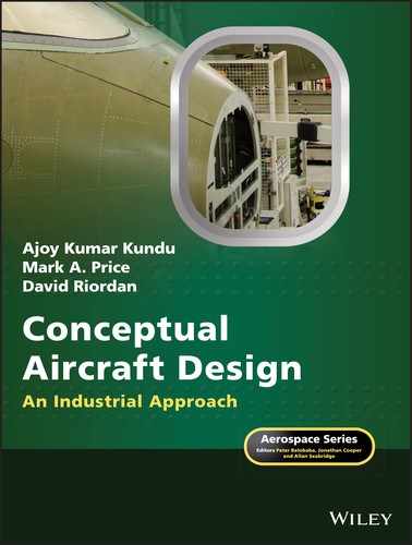
To certify aircraft airworthiness, there are three measuring points in the airport vicinity to ensure neighbourhood living is within the specified noise limits. Figure 21.2 gives the distances involved to locate the measuring points. They are as follows:
- Takeoff reference point −6500 m (3.5 nm) from the brake release (start) point and at an altitude given in Figure 21.2.
- Approach reference point −2000 m (1.08 nm) before the touchdown point, which should be within 300 m from the runway threshold line and maintain at least a 3° glide slope with the aircraft at least at an 120 m altitude.
- Side‐line reference point −450 m (0.25 nm) from the runway centre‐line. At the side‐line there are several measuring points along the runway. This is measured at both the sides of the runway.
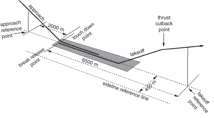
Figure 21.2 Noise measurement points at takeoff and landing.
ICAO, Annex. 16, Vol. I, ch. 3 maximum noise requirements in EPNdB are given in Table 21.4 and is plotted in Figure 21.3.
Table 21.4 EPNdB limits (Make linear interpolation for in between aircraft masses).
| Takeoff (make linear interpolation for in between mass) | ||||||
| No. of engines | 2 | 3 | 4 | |||
| MTOM, kg | ≤48 100 | ≥385 000 | ≤28 600 | ≥385 000 | ≤20 200 | ≥385 000 |
| EPNdB limit | 89 | 101 | 89 | 104 | 89 | 106 |
| aCut‐back altitude, m | 300 | 260 | 210 | |||
| Approach – any number of engines (make linear interpolation for in between mass) | ||||||
| MTOM‐kg | ≤35 000 | ≥280 000 | ||||
| EPNdB limit | 98 | 105 | ||||
| Side‐line – any number of engines (make linear interpolation for in between mass) | ||||||
| MTOM, kg | ≤35 000 | ≥400 000 | ||||
| EPNdB limit | 94 | 103 | ||||
aIn certain airports, engine throttle cut‐back (lower power setting) are required to reduce noise levels after reaching the altitude as shown in the table. At cut‐back, the aircraft should maintain at least a 4% climb gradient. In the event of an engine failure, it should be able to maintain altitude.

Figure 21.3 ICAO noise requirements.
A typical footprint of the noise profile around runway is shown in Figure 21.4. The engine cut‐back area is shown in the figure along with re‐established the rated thrust for en route climb. Residential development may avoid the noise footprint areas.

Figure 21.4 Typical noise footprint (≈10 km long) of aircraft showing the engine cut‐back profile.
The airframe also produces a significant amount of noise, especially when the aircraft is in a ‘dirty’ configuration. Figure 21.5 gives the sources of noise emanating from the airframe. The entire wetted surface of the aircraft, more so by the flow interference at the junction of two bodies (e.g. at wing‐body junction), produces some degree of noise based on the structure of the turbulent flow causing pressure pulses audible to the human ear. It becomes aggravated when the undercarriage and flaps/slats are deployed creating considerable vortex flow and unsteady aerodynamics; the frequencies of fluctuations appear as noise. At the conceptual design phase, care must be taken to minimise gaps, provide fillets at the two body junction, make streamlined struts and so on. Noise increases with speed increase. Care is to be taken to eliminate acoustic fatigue in structure and make them damage tolerant; material selection plays an important role (Figure 21.6).

Figure 21.5 Typical sources of noise emanating from an airframe.
Source: Reproduced with permission of Cambridge University Press.
Typical noise levels from various sources are given in Figure 21.7 both at takeoff and at landing. Evidently, engine contribution is the dominant one, which reduces at landing when the engine power is set low and the jet efflux noise reduces substantially. Noise emanating from the airframe is more at landing on account of higher flap/slat settings and the aircraft altitude is lower at the measuring point than at the takeoff measuring point. Since the addition of noise level is done on a logarithmic scale, the total level of noise contribution during takeoff and landing is nearly the same.

Figure 21.6 Relative noise distributions from various aircraft and engine sources.
The engine and nacelle are the main sources of noise at takeoff when it is running at maximum power. All the gas turbine components, for example, fan blades, compressor blades, combustion chamber walls and turbine blades, generate noise. With the increase of bypass ratio (BPR) the noise level goes down as low exhaust velocity reduces shearing action with the ambient air. The difference in noise between an afterburning turbojet and high BPR turbofan can be as high as 30–EPNdB. Figure 21.7 shows that, at subsonic flight speed, the noise radiation moves ahead of the aircraft.

Figure 21.7 In‐flight turbofan noise radiation profile.
Propeller‐driven aircraft operation has to consider noise emanating (radiation and reflection) from the propellers. Here, the noise reflection pattern depends on the direction of propeller rotation as can be seen in Figure 21.8. The spread of reflected noise also depends on propeller position with respect to the wing and fuselage.
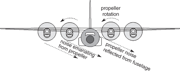
Figure 21.8 Noise considerations for propeller‐driven aircraft.
Inside the cabin, the noise comes from the environmental control system (ECS) and needs to be kept at its minimum level. These problems are tackled by the specialists. Details of cabin interior design considerations are taken up in Phase II of the project.
21.6.2 Engine Exhaust Emissions
Currently, the civil aviation sector burns about 12% of the fossil fuel consumed by the worldwide transport industry. It is responsible for about 3% of the annual addition to greenhouse gases and pollutant oxide gases. The environmental debate got hotter on the issues of climate change, depletion of ozone layer and so on, leading into the debate on long term effects of global pollution. Smog is made of nitrogen oxide that affects human pulmonary and respiratory health. The success of the automobile industry in controlling engine emission is clearly evident from the dramatic improvement achieved in many metropolises.
The US Environment Protection Agency (EPA) saw this problem some time ago. The 1980s emphasised the need for government agencies to tackle the engine emission issues. The early 1990s (Kyoto agreement) brought a formal declaration to limit pollution (locally around airports). Currently, there are no regulations for the cruise segment. In the USA, the FAR 34 and for the international body the ICAO (Annex. 16 Vol. II) outline the emission requirements. The EPA has worked closely with both the FAA and the ICAO to make the standards very close to each other. Although military aircraft emission standards are exempt, increasingly they are coming into scrutiny to follow Milspecs standards. Emission is measured by an Emission Index (EI).
Combustion of air (oxygen + nitrogen) and fuel (hydrocarbon plus small amount of sulfur) should ideally produce carbon dioxide (CO2), water (H2O), residual oxygen (O2) and traces of sulfur particles. In practice, the combustion product consists all of these plus an undesirable amount of pollutants such as carbon monoxide (CO – toxic), un‐burnt hydrocarbon (UHC), carbon soot (smoke – affect visibility), oxide of sulfur and various oxides of nitrogen (NOX – affects ozone concentration). The aim of the regulations is to reduce the level of undesirable pollutants by improving combustion technology. Sustenance of air‐travel and industry growth would depend on how technology can keep up with the demands for human health preservation.
Lower and slower flying reduces the EI. This is in conflict with market demand of flying higher and faster. Designers will have to make compromises. Reduction of EI is the obligation of engine manufacturer and hence the details of airworthiness requirements on EI are not given here. These can be obtained from the respective FAA and ICAO publications. Aircraft designers will have to depend on engine designers to supply certified engines complying with the regulatory standards. There is no classroom work from this section.
21.7 Flying in Adverse Environments
This section briefly discusses problems associated with flying in icy conditions, foggy weather, turbulent weather, wind shear, jet stream and thunderstorms. Ice, rain, fog and turbulence are adverse environments for aircraft to fly in. These fall in to two groups: (i) an adverse environment with loss of visibility and (ii) an adverse environment due to aerodynamic and stability/control degradation, as follows.
21.7.1 Group 1 – Adverse Environments due to Loss of Visibility
Loss of forward visibility and horizontal reference can affect pilotperformance and accidents have happened due to pilots being unable to see or judge flight obstacles and/or aircraft attitude. Lack of visibility is like flying on dark cloudy nights. Fortunately, degraded visibility does not affect aircraft performance, stability and control other than affecting pilot skill. Flight deck instruments prove adequate under skilled hands. There are three main types of environmental conditions that affect pilot visibility, described next.
- Atmospheric fog. There are different kinds of reasons for fog formation and it can appear suddenly. Normally, it occurs at lower altitudes; at higher altitudes the visibility problems arise from flying in cloud. Takeoff and landing become difficult or an obstacle not is seen at any altitude until it is too late. Lack of a horizon reference can make an aircraft enter in to a spiral dive, which is not easy to detect in the initial stages by inexperienced pilots. Commercial aircraft pilots must have instrument‐flying training. Forward scanning radar fitted to the aircraft is of considerable assistance. In any case, it is better to wait until the fog is cleared, normally in a relatively short time. In case a pilot confronts foggy conditions on landing, landing should be undertaken under an Instrument Landing System (ILS) supported by the airport control tower. If possible, a pilot should loiter around close by where there is visibility until destination airport fog conditions improve. In the worst case, a pilot could opt for alternative airport provided there is sufficient fuel.
- Flight‐deck fog. This is like what can occur in a motor vehicle. Flight‐deck fog has to be removed. The defogging system is like that of a car with an embedded electrical wire in the windscreen. Figure 18.1a shows a generic layout with wipers representing the BAE RJ family in better detail.
- Heavy rain. Heavy rain can also impair vision. The rain‐removal system is also like a car using windscreen wipers. Also, rain‐repellent chemicals assist in rain removal. Section 22.7.1 describes the rain‐repellent system in better details.
21.7.2 Group 2 – Adverse Environments due to Aerodynamic and Stability/Control Degradation
Flying in adverse environments affecting aircraft performance, stability and control falls into two types as follows.
- Aerodynamic degradation. Ice formation on the aircraft surface affects the skin condition and considerably increases drag. In addition, ice formation on critical areas of lifting surfaces, intake and internal engine components develops into a dangerous situation with loss of lift and power. Ice accretion at the leading edge deforms the required aerofoil contour, disturbing smooth streamline flow causing premature early stall. It is difficult to notice visually clear ice forming at early stages and therefore engineers make provision to remove ice accretion described in better details next. Figure 21.9 shows typical icing envelopes [5].
- Anti‐icing, De‐icing. Icing is a natural phenomenon that occurs anywhere in the world depending on weather condition, operating altitude and atmospheric humidity. Ice accumulation on wing/empennage and/or engine intake can have disastrous consequences. Icing increases drag and weight, decreases lift and thrust and even degrade control effectiveness. On the wing/empennage, icing will alter the profile geometry leading to loss of lift. Ice accumulation at the intake will degrade engine performance and can even damage the engine if large chunks are ingested. It is a mandatory requirement to keep the aircraft free from icing degradation. This can be achieved either by anti‐icing that never allows ice to form on critical areas, or by de‐icing that allows ice build‐up to a point and then shed it just before it becomes harmful. De‐icing results in blowing chunks of ice away and these should not hit or get ingested by engine.
Figure 21.9 Typical icing envelope [3].
There are several methods for anti‐icing and de‐icing. Not all anti‐icing, de‐icing, defog and rain‐removal systems use pneumatics. These are primarily electrical systems but are included in this section to continue with the subject matter. Section 22.7 describes the anti‐icing system in better detail.
- Aircraft stability/control degradation. These are due to influence of weather disturbances, for example, turbulent weather, wind shear, thunderstorms and jet streams are the main causes that affect aircraft stability/control and can degrade to dangerous conditions. These are described separately next. Weather related disturbances primarily concerns with control of aircraft, bearing in mind that there is a sufficient stability margin to control the aircraft satisfactorily in any inadvertent situation. Meteorological offices routinely circulate weather forecasts, which all pilots must study and use to make flight plans. Meteorology is an involved science beyond the scope of this book. Here, only the effects of adverse weather are touched upon. Flight planning must accommodate necessary provisions to encounter bad weather.
- Turbulent weather. Random unsteady atmospheric wind flow that can change direction is seen as turbulent weather. There are several ways turbulence develops, for example, weather conditions or ground contour/heat distribution developing convective currents. These can come as gusts of wind vibrating the aircraft in motion and sometimes can be severe enough to throw passengers from their positions if they are not secured with restraints such as seat‐belts; injuries have happened. Modern transport aircraft are fitted with auto‐stabilisation that dampens the shaking of aircraft to a considerable extent but in strong turbulence the aircraft can suffer a heavy, bumpy ride. All passengers must adhere to the cabin safety instructions to stay with seat‐belts on for their own safety.
FAA has requirements that transport aircraft must withstand a 66 ft s−1 upward gust (see Chapter 17). Typically, a weather report can give the areas under turbulent conditions and good weather radar can detect strong turbulences. Pilots should avoid flying through these conditions by making diversions; normally flight planning accommodates extra fuel for possible diversions, which is usually not a long detour.
A strong downward gust can make an aircraft to lose considerable height. At low altitudes, say at approach, a strong downwind can prove dangerous. The destination airfield offers local weather conditions and pilots remain alert to control their aircraft in any inadvertent conditions.
However, at high altitude around tropopause, turbulence can appear as Clear Air Turbulence (CAT) that is not easy to detect and can be severe. Wind shear and jet stream are associated with CAT.
- Jet stream. Around the tropopause there is a global pattern of periodic tube‐like (relatively thin but very wide) wind flow in long stretches from west to east in the mid latitudes of the Northern Hemisphere. When the average wind velocity exceeds 50 kt, it is seen as a jet stream; its core can have a high velocity exceeding 100 kt. This is an unsteady state and its size and strength keep changing. There can be considerable fuel savings in the jet stream when flying eastward and vice‐versa in the Southern Hemisphere.
- Wind shear. An aircraft enters into wind shear when it enters a zone where wind speed changes in magnitude and direction. The aircraft must be able to adjust to these changes; generally, it is controlled through the disturbance in a relatively short time. A downdraft will make an aircraft sink rapidly, which can be observed on the flight deck instruments. Aircraft sinking when flying close to the ground, say at approach to land, can pose a hazardous situation. Pilots need to remain alert at takeoff and landing phases to control the aircraft from hitting ground.
- Thunderstorm/cloud. Thunderstorms are violent outbursts in the atmosphere and are always associated cumulonimbus cloud (cumulonimbus clouds are nimbus clouds in the form of a rising cumulous cloud). The violent nature can be observed by their swirling pattern moving mainly upward. Their gusts can easily exceed the design limits and can have catastrophic consequences if flown into. Tornados/hurricanes are manifestations of these outbursts. Thunderstorms also produce strong up and down bursts. They must be avoided. Fortunately, thunderstorm areas can be easily located so pilots can detour the area. In low intensity thunderstorms, pilots may fly through after studying the nature but precautionary measures must be taken for both passengers and crew. There are prescribed procedures to fly through permissible thunderstorms.
Lighting strike and hail are associated with thunderstorms. Lightning is the electrical discharge of the static electricity that accumulates. The direction discharge goes towards the maximum potential difference and branches out in different directions; this can be within the cloud or may strike the ground. The vast expanse of thunder clouds develops a very high voltage and current that can be destructive, and this is another reason for pilots to detour the area. Aircraft are equipped to discharge static electricity build‐up and the shell insulates the interior. However, they are not designed to fly through severe thunderstorms. Lightning strikes are common and in the majority of cases, in a way, are harmless and the mission continues safely but an extreme strike can create an impact that can cause operational interruptions. Lightning protection is incorporated to reduce lightning strike impact. Most strikes occur between 8000 ft and 16 000 ft altitudes when aircraft are in climb or descent.
Glider pilots seek updraft from thermals to gain altitude. They often take advantage of the upward flow of small cumulous clouds at the early stages that may be seen as patches of cotton floating in interesting shapes. Pilots must be trained to recognise which ones are harmless.
21.7.3 Bird Strikes
Birds can create adverse flying environment. An open span of grass field around the runway as a safety zone is an ideal feeding ground for birds – seeds, grains, inspects, worms and so on abound. Some even make their permanent home there and keep breeding. They can also come from outside in a large flock. Although the birds are used to aircraft noise, they may be spooked into flying in the aircraft flight path during takeoff and landing when their ingestion to the engine is not uncommon. In many instances a single small bird ingestion by the engine may not be felt but experienced pilots can recognise it by observing engine gauges and from the feel. In some occasions, the aircraft continues towards the destination airport and bird strike evidence is found after landing. Aircraft certification authorities have mandatory requirements to demonstrate safety by throwing fresh dead chickens known as the chicken test. Most bird strikes occur around an airfield where birds rarely exceed the size of a chicken. However, large bird strike is a different matter.
The recent Hudson River landing of an Airbus320 after both engines failed on account of bird strike (possibly geese) is a well‐published case of the kind of accident that can happen. Landing on water has happened many times before but is a glaring example of what can happen with bird strike. At higher altitudes, vulture strikes have occurred many times. There are cases when even older military aircraft with sensitive engines fell due to bird strike from a bird as small as a sparrow.
Birds around an airport can be driven out, at least for a temporary period. Various studies have been made to drive them out with temporary success. Constant surveillance (nowadays with drones), various scaring techniques and environmental planning can keep flight operations continuing. Bird line drones are in use to drive out any wildlife incursion in an airfield area. Over long period of time, these may become an effective measure to some extent. However, stray birds away from an airfield are a random occurrence. Bird strike at high aircraft speed means that the impact force is much higher and can be felt by pilots. Pilots must then land to the nearest available airport for safety reasons; successful landing on the Hudson River is now incorporated as a pilot drill measure if landing on an airfield is not possible. Without a stretch of water and airfield, a pilot has to take action as he/she judges.
21.8 Military Aircraft Flying Hazards
In additions to the hazards of flying as described previously, military aircraft have face additional hazards when flying at low altitudes, especially through terrain as a cover. There are hazards in hard manoeuvres to engage or disengage in combat at lower altitudes. As some measure of safety, military aircraft are fitted with Ground Proximity Warning Systems. Of late, modern civil transport aircraft above 30 000 lb MTOW are also fitted with Ground Proximity Warning Systems. These instruments sense terrain and ground below to warn pilots in time to react (typically 1 s) according to safety. All types of aircraft, even small recreational aircraft flying through valleys for sightseeing must keep adequate separation distance if a manoeuvre, for example. turning and climb‐out, is required. A pilot's understanding of the surroundings, be it terrain or other aircraft, is essential even when a terrain map and Ground Proximity Warning Systems are integrated with the aircraft.
Military aircraft jettisoning stores in certain manoeuvres can be hazardous if they hit any part of aircraft. There have been cases when light empty drop‐tanks have tumbled at jettison hitting the empennage.
21.8.1 Aircraft Combat Survivability
New combat aircraft capabilities are evaluated in simulated environments in twin platform, the other platform being that of the adversary's capabilities to the extent it can be ascertained in terms of combat scores. These are based on mathematical modelling with measurable parameters, for example, susceptibility (inability to avoid adversary interception), vulnerability (inability to withstand a hit) and killability (inability to both). The general term ACS refers to the capability of aircraft survivability disciplines attempts to maximise the survival of aircraft in wartime. This is in addition to system safety attempts to minimise those conditions known as hazards that can lead to mishaps in environments not arising from combat. These topics are beyond the scope of this book.
Section 22.8 covers some of the systems incorporated as measures for combat survivability.
21.9 End‐of‐Life Disposal
Like any other machinery, their useful operation ceases on account of wear and tear or being no longer economic to operate when replaced by newer models; the example of a car is a glaring one. Aircraft is no exception on functionality, especially under strict safety/environment regulations. It is estimated that over tens of thousands of civil aircraft will cease to operate in the next two decades, each costing millions of US dollars when purchased new. Already, there are 1000 of disused civil and military aircraft stored in Arizona, California and New Mexico covering 1000 of acres, loosely termed an aircraft graveyard. These decommissioned aircraft still carry value as scrap and even some components can be recycled/reused. There are guidelines for storage, offering decommissioning, dissemble, dismantle, recycle/disposal and value extraction. The aircraft designers have to heed these guidelines to facilitate the process of salvaging the aircraft.
Metals sold as scrap can be recycled but more and more composite material is now piling up. Disposal of composite material is difficult as they serve no useful purpose as scrap – attempts are in hand to make them recyclable. Avionics boxes and microprocessors contain toxic material. Fluids in display units are also toxic. It would cost to get rid of the toxic material from the environment. Even incineration plants are specifically designed to keep the efflux clean.
More and more researches are continuing to find suitable materials that are less toxic and can be disposed of cost effectively. This is a matter for material scientists. However, aircraft designers must stay updated with materials technology and choose the correct kinds.
Conceptual aircraft designers should make considerations that will facilitate an easy to dissemble arrangement and use as many recyclable materials and equipment as possible to maximise valorisation and minimise land‐fill waste.
21.10 Extended Range Twin‐Engine Operation (ETOP)
In past, twin‐engine transport aircraft were not allowed to fly over water for safety reasons in case an engine fails losing half the power coupled with any other reason for the other engine not to supply adequate power. Losing an engine increases aircraft drag (see Section 22.8). Any twin‐engine commercial transport aircraft is restricted to operating within land mass on a route where an emergency airfield is available, in case an emergency demands a landing. Chapter 15 did not compute the ETOP range. In this section, its background is explained and readers may attempt compute the range using the same procedure with the effects of an engine failure and drift down procedure dealt in [6].
However, confidence built up as engines became more reliable when failure at cruise power rating became a rare occurrence. In 1980, the FAA negotiated with operators and manufacturers to allow flying over water up to a distance that ensures that in case of emergency the aircraft can land at a suitable airport in 120 min under one engine powered up to maximum climb (i.e. continuous) rating. The operation is known as an ETOP. With success of ETOPS with a 120 min limit, the FAA subsequently raised the time limit to 180 min (in head‐wind less range). This extension of time limit improved the fuel efficiency of operation.
21.11 Flight and Human Physiology
Defying gravity could be dangerous if the laws of the nature are not fully understood ([7–10]). Apart from solving the laws of physics to make aircraft fly and gain altitude there is the additional issue of understanding the nature of human physiology and its limitations. Inadequacy in medical condition of a pilot is an actual threat to survival. Qualifying for medical airworthiness is mandatory for all pilots; its level of stringency differs for the class of aircraft to be operated, combat pilots have the strictest requirements. Even for fit pilots, the influence of drug/alcohol can affect medical airworthiness. Aviation physiology is a subject on its own and is now a mature science for understanding medical human factors, their limitations and pilot response characteristics.
There are two main limitations based on (i) altitude effects and (ii) gravitation loads, which can be different from unit load (1 g) as one experiences in day to day living. These two aspects are briefly described next.
- Effects of Altitude. Pressure and density of atmosphere decreases in non‐linear manner (see Section 1.15). Human habitation in Himalayan terrain at around 10 000 ft exists. By far the majority of normal habitation is below 3 000 ft. It has found that humans can sustain unassisted up to 14 000 ft. Therefore, aircraft flying above that altitude must have ECS to keep pressure at an acceptable limit typically around 7000–8000 ft depending on design (see Section 15.2). With adequate pressurisation, oxygen supply for human need is simultaneously met. However, when the inadvertent situation of cabin depressurisation occurs, then an emergency oxygen supply is necessary. The ECS takes engine air flow bleed at about 2–3% degradation of engine performance affecting fuel economy (see Section 12.7). Aircraft make rapid descent to a safe altitude below 10 000 ft.
- Effects of g‐load. In manoeuvre (see Chapter 17), an aircraft experiences g‐load. There two kinds of g‐load: (a) instantaneous g‐load and (b) sustained g‐load. Instantaneous g‐loads are of short duration lasting a few seconds and humans can tolerate higher loads than sustained g‐load, which can last longer (in space travel, initial booster g‐load load on astronauts can last in excess of 4 min). Military pilots with g‐suits have experienced instantaneous g‐load of 12 g; extreme aerobatic aircraft are designed to withstand 9 g. Sustained g‐load for military aircraft is 6 g and for extreme aerobatics aircraft can take 6 g. A typical Ferris‐wheel/merry‐go‐round is around 2–3 g.
Aircraft pull outs from a dive/loop in high g‐load prevents blood from the heart reaching the brain causing black‐outs and a pilot can temporarily lose consciousness, which is of course dangerous. It is for this reason that military aircraft seats are more inclined to reduce the carotid distance, easing blood flow to the brain. Astronauts lay horizontal to withstand sustained g‐load. At negative g, a pilot can enter weightlessness with a different kind of reaction, some enjoy this. At extreme high negative g, disorientation of the pilot can occur.
21.11.1 Aircraft Design Considerations for Human Factors
A combat flying mission stretches the pilot to the limits of human capability; in loose terms, an inhuman task. It requires expensive long training of handpicked individuals by rigorous testing of their physical and emotional fitness. High levels of information processing as multitasking of safety critical and mission critical workload is stressful and under physical stress, as described before, can impose considerable fatigue leading to erroneous pilot judgement in executing the correct procedures that can result into catastrophic consequences. Aircraft designers have the obligation to assist pilot cognitive (situation awareness) functions under duress.
Aircraft designers search for inventing appropriate facilities to ease pilot stress, thereby improving operational safety. The examples of autopilot, ILS, microprocessor‐based fly‐by‐wire (FBW)/full authority digital engine control (FADEC), HUD, EFIS, ECS, anti‐g pressure suits, voice operated commands, back‐to‐base system and so on are many examples, most of which have become standard features as the mission demands. Configuring the flight deck to offer a comfortable pilot work environment is an essential design obligation, so are the requirements for passenger cabin configuration.
Military aircraft flight deck configuration and design are considerably more complex than for civil aircraft flight decks. A military flight crew requires a specially designed suit with ECS and pressurisation for high altitude and high‐g operation. The flight deck should not bear any light signature during night flying, requiring specially designed ‘eyebrow’ lights for instrument reading. Ejection seats are standard features for survival design consideration. Vibration and flight deck noise reduction are integral to design.
Some of the automations are old inventions, one such invention is ‘autopilot’. Incorporation of all round rapidly growing microprocessor‐based systems bear the marks of progress. It will not be long until designers start their conceptual design studies for drone‐like fully automated commercial transport aircraft, the cargo versions leading the way.
In the past it has been observed that conversion from older procedures to modern FBW procedures, with multi‐functional displays, have caused considerable difficulty with cases of accidents and incidents. Improved training methods and use of flight simulators have practically eliminated such difficulties. Other human factors to consider are the emotional stability under severe workload related stress in emergency, physical incapacity for whatever the reason (apart from being wounded in combat) and so on.
21.11.2 Automation – Unmanned Aircraft Vehicle (UAV)/Unmanned Aircraft System (UAS)
This book is not on UAV/UAS (synonymous terminologies). Readers may refer to Ref. [11] for a detailed treatise on UAV/UAS. However, it may interest readers to examine the consequence of removing human limitations as design constraints, the UAV/UAS offers enhanced scope for performance capability using the technologies dealt with in this book.
The following are the areas affected by the absence of on‐board human occupation.
- The ‘g’ is level can be relaxed to a considerable higher limited on‐board instrument limits, typically 3–4 times higher, if required to still higher values.
- Human comfort level of ECS considerations are not required. The system can be designed to extreme weather considerations within the terrestrial flight envelope.
- Higher payload capability for not having systems required for humans on‐board.
- Relaxed airworthiness requirements.
- UAV/UAS are software driven machines that can be autonomous or ground based pilot controlled, requiring the transmitter‐receiver set to communicate.
- For long endurance operations, ground‐based pilots can avoid fatigue by working in shifts to stay sharp in cognitive function.
- On‐board pilotless combat aircraft has no human pilot risking their life, at the same time they are vehicles capable of higher performance capabilities. Such vehicles are already in production.
- Civil application of a fixed wing bears greater promise but waits infrastructure support and marketability. Copter like drones (UAV/UAS) are already in the early stages of civil applications.
Readers are encouraged to explore possibilities as entrepreneurs to the many areas of possible applications in this early stage of development.
21.12 Some Emerging Scenarios
There are four topics; two arising from terrorist activities, one concerns health issues and one is an old problem arising from aircraft debris on runway. This section is included to keep future designers aware of the kinds of problems one may face.
21.12.1 Counter‐Terrorism Design Implementation
Thought is now given to whether there could be ways to counter on‐board terrorism. The consideration is topical and yet to be decided on for implementation. It will increase aircraft weight and cost. Some of the areas of design changes are as follows:
- Make a bullet‐proof flight‐deck barrier at the cockpit door. Make the cabin compartmentalised to isolate trouble. How effective these are needs to be debated but the aircraft designers must stay ahead with some forethought than afterthought.
- Improve the structural integrity of cargo compartment/bay against in‐flight explosions. The space below the floorboard needs to be compartmentalised and have a shock absorbing/impact resisting shell structure to retain integrity in the event of a local explosion.
- Aircraft flight systems to have automated recovery, homing to the nearest airfield and landing. Military aircraft already have such systems.
21.12.2 Health Issues
A steady annual increase in passenger numbers crossing international boundaries brings in health issues that need to be attended to. This means making space allowance (like cruise ships) to treat/isolate patients. Up until now, these were attended to on an ad hoc basis but manufacturers can increase market appeal with health‐care facilities, especially for very large aircraft flying long haul. Cardio‐vascular problems, pregnancies, isolated infections and many other kinds of emergency health cases are ever increasing during flights.
21.12.3 Damage From Runway Debris (an Old Problem Needs a New Look)
The catastrophic crash of Concorde was a result of runway debris hitting fuel tank making it burst and catch fire. This sends a signal to protect vulnerable areas with stronger impact resistant material. This is a relatively easy task but designers need to examine the point in a new design. This will incur additional weight and cost.
As a preventive measure, regular runway inspection is now a routine procedure for all airfields using well‐equipped land vehicles. However, use of drones is gaining ground not only for runway inspection but also readily inaccessible surfaces of aircraft; for example, large aircraft wing/fuselage surfaces using high resolution cameras.
References
- 1. Smith, M.J.T. (1989). Aircraft Noise. Cambridge University Press.
- 2. Ruijgrok, G.J.J. (2003). Elements of Aviation Acoustics. Eburon.
- 3. ESDU 02020, An Introduction to Aircraft Noise. Available online at https://standards.globalspec.com/std/1643052/esdu‐02020 (accessed June 2018), ESDU.
- 4. Gunston, W. (2002). The Development of Jet and Turbine Aero Engines. Sparkland, Somerset: Patrick Stephens.
- 5. Torenbeek, E. (2013). Advanced Aircraft Design: Conceptual Design, Technology and Optimization of Subsonic Civil Airplanes. Wiley.
- 6. Kundu, A.K., Price, M., and Riordan, D. (2016). Theory and Practice of Aircraft Performance. Wiley.
- 7. Garland, D.J., Wise, J.A., and Hopkins, V.J. (1999). Handbook of Aviation Human Factors. London: Lawrence Erlbaum Associates Publishers.
- 8. Dhenin, G. (ed.) (l978). Aviation Medicine: Health and Clinical Aspects. London: Tri‐Med Books Limited.
- 9. Society of U.S. Air Force Flight Surgeons. Flight Surgeons Handbook of Life Support Equipment, l Oct 1987.
- 10. Shannon, R.H. Operational aspects of forces on man during escape in the U.S. Air Force, l January l968–31 December l970. In AGARD Linear Acceleration of Impact Type, June l971.
- 11. Grundlach, J. (2014). Designing Unmanned Aircraft Systems: A Comprehensive Approach, 2e. Reston, USA: AIAA.