1
Introduction
1.1 Overview
This book covers design studies on fixed winged aircraft and the conceptual stage of a project in detail, covering both civil and military aircraft types except for the V/STOL. Chapter 1 begins with a brief historical introduction, surveying our aeronautical legacy to motivate readers by describing the remarkable progress made from mythical conceptions of flight to high‐performance aircraft with capabilities unimagined by early aeronautical pioneers. This is followed by presenting the issues involved with units and dimensions as well other pertinent topics; for example, cost implications and ending with a study of the atmosphere.
This chapter covers the following topics:
- Section 1.2: A Brief Historical Background
- Section 1.3: Aircraft Evolution
- Section 1.4: Current Design Trends for Civil and Military Aircraft
- Section 1.5: Future Design Trends for Civil and Military Aircraft
- Section 1.6: Forces and Drivers
- Section 1.7: Airworthiness Requirements
- Section 1.8: Current Aircraft Performance Analyses Levels
- Section 1.9: Comparison Between Civil and Military Design Requirements
- Section 1.10: Topics of Current Research Interest Related to Aircraft Design
- Section 1.11: Cost Implications
- Section 1.12: The Classroom Learning Process
- Section 1.13: Units and Dimensions
- Section 1.14: Use of Semi‐Empirical Relations and Graphs
- Section 1.15: Atmosphere
Current trends indicate maturation in the technology of classical aeronautical sciences with diminishing returns on investment, making the industry cost conscious. To sustain the industry, newer avenues are being researched through better manufacturing philosophies and exploiting the trends in price and weight reduction of newer bought‐out avionic items and of composite materials. Future trends indicate globalisation, with multinational efforts to advance technology making it better, faster and less expensive than the existing limits.
Some of the discussions in this chapter are based on personal experiences and are shared by the authors' many colleagues in several countries. Aerospace is not only multidisciplinary but also multidimensional – it may look different from varying points of view. The final product converges to similarity for the comparable designs.
The readers must go through Section 1.15 in detail. The examples given here should cover the needs of this book and readers must be able work through them.
1.2 Brief Historical Background
This section provides a very brief history of flight, designed to motivate individuals to explore human aerial achievements further. Many books cover the broad sweep of aeronautical history while others discuss specific accomplishments and famous people's achievements in aeronautics. The references [1–4] are good places to start your exploration. Innumerable web sites on historical topics and technological achievements exist; simply enter keywords such as Airbus, Boeing or anything that piques your curiosity and you will find a wealth of information.
1.2.1 Flight in Mythology
People's desire to fly is ancient – every civilisation has their early imaginations embedded in mythologies. There are the well‐known examples, for example, in Greek mythology Daedalus and his son Icarus flew on wings made from wax and feathers, flying chariots in Indian mythologies and their successors vimanas, flying‐carpets in many Middle Eastern folk traditions and so on. Flying creatures also populate our early myths including the bird‐man (Garuda), flying horses (Pegasus/Sleipnir) and flying dragons. The imagination of flight is universal. Readers may explore these and other mythical conceptions of flight through Internet searches.
History is unfortunately more ‘down‐to‐earth’ than mythology with stories about early pioneers who leapt from towers and cliffs, only to leave the Earth in a different but predictable manner because they did not respect natural laws. Human dreams and imagination became reality only a little over 100 years ago on 17December, 1903, when the Wright brothers succeeded with the first powered heavier‐than‐air flight. It only took 65 years from that date to land a man on the Moon.
1.2.2 Fifteenth to Nineteenth Centuries
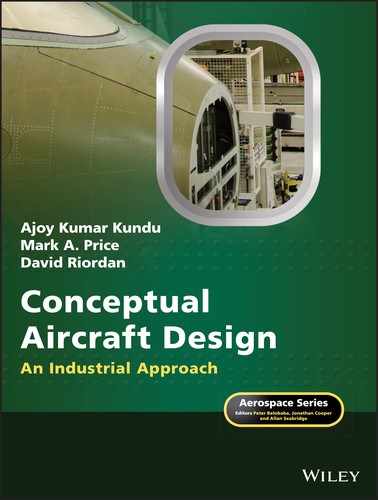
Our chronicle of known flight begins with tethered kites flown in China as long ago as 600 B.C. The first scientific attempts to design a mechanism for aerial navigation are credited to Leonardo da Vinci (1452–1519). He was the grandfather of modern aviation, even if his machines never defied gravity. He sketched many contraptions (Figure 1.1a) in his attempt to make a mechanical bird. Birds, who provided his inspiration, possess such refined design features that the initial human path into the skies could not take that route. Today's micro‐air devices are increasingly exploring natural designs. After da Vinci, there was an apparent scientific lull for more than a century until Sir Isaac Newton (1642–1727) computed the power required to make sustained flight. The idle period may simply be the lack the documentary evidence for it is inconceivable that human fascination with flight abated in this period. Flight is essentially a practical matter, so real progress paralleled other industrial developments (e.g. isolating gas for buoyancy).
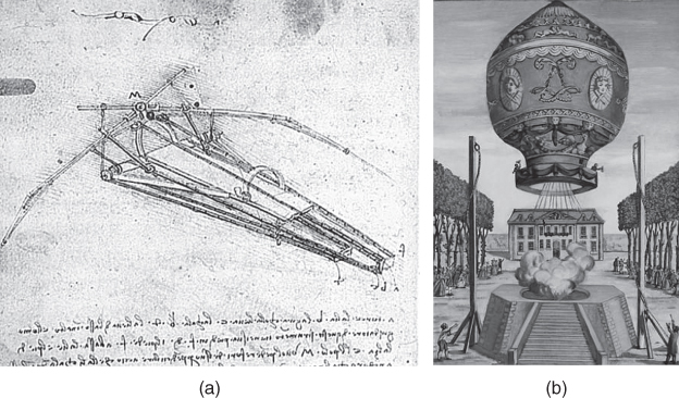
Figure 1.1 Early concepts and reality of flying. (a) Leonardo's flying machine (idea) and (b) Montgolfier Balloon (reality).
Source: reproduced with permission of NASA.
While it appears that Bartolomeu de Gusmao may have demonstrated balloon flight in 1709 [4] in Portugal; information on this event is still lean. So, we credit Jean‐François Pilâtre de Rozier and François Laurent d'Arlandes as the first people to effectively defy gravity, using a balloon designed by the Montgolfier brothers (France) (Figure 1.1b) in 1783. For the first time, it was possible to sustain with limited control in air flight. These balloon pioneers were subject to the prevailing winds and were thus limited in their navigational options. In 1784, Jean‐Pierre Blanchard (France) with Dr John Jeffries (USA) added a hand‐powered propeller to a balloon and made the first aerial crossing of the English Channel on 7 January, 1785. (Jules Verne's fictional balloon trip around the world in 80 days became a reality when Steve Fossett circumnavigated the globe in fewer than 15 days in 2002.) In 1855, Joseph Pline was the first to use the word aeroplane in a paper he wrote proposing a gas‐filled dirigible with a propeller.
It was not until 1804 that the first recorded controllable heavier‐than‐air machine to stay freely airborne was recorded when Englishman Sir George Cayley constructed and flew a kite‐like glider (Figure 1.2a) with movable control surfaces. In 1842, an English engineer Samuel Henson secured a patent on an aircraft design that was driven by a steam engine.
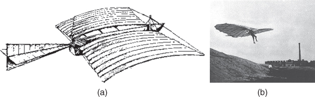
Figure 1.2 Heavier‐than‐air unpowered aircraft. (a) Cayley's kite plane and (b) One of Lilienthal's gliders.
Source: reproduced with permission of NASA.
With his brother Gustav, Otto Lilienthal was successfully flying gliders (Figure 1.2b) in Berlin more than a decade (1890) before the Wright brothers' first experiments. His flights were controlled but not sustained. Sadly, Lilienthal's aerial developments ended abruptly and his experience was lost when he died in a crash in 1896.
The early flight machine designs were hampered by an overestimation of the power requirement needed for sustained flight. This mistake (based in part on Newton and others calculations) may have discouraged attempts of the best German engine makers of the time to build aircraft engines because they would have been too heavy.
1.2.3 From 1900 to World War I (1914)
The question of who was first in flight is an important event to remember. The Wright brothers (United States) are recognised as the first to achieve sustained, controlled flight in a heavier‐than‐air manned flying machine (Wright Flyer, Figure 1.3a). Before discussing their achievement, some ‘also‐rans’ deserve mention. John Stringfellow accomplished the first powered flight of an unmanned heavier‐than‐air machine in 1848 in England. In France, Clement Ader also made a successful flight in his ‘Eole’. Gustav Weisskopf (Whitehead), a Bavarian who immigrated to the United States, claimed to have made a sustained, powered flight [3] on August 14, 1901, in Bridgeport, Connecticut. Karl Jatho of Germany made a 200‐ft hop (longer than the Wright brothers' first flight) powered (10‐HP Buchet engine) flight on August 18, 1903. At what distance a ‘hop’ becomes a ‘flight’ could be debated.
Figure 1.3 Heavier‐than‐air powered aircraft. (a) The Wright Flyer and (b) Langley's Aerodrome catapult launch.
Source: reproduced with permission of NASA.
Perhaps most significant are the efforts of Samuel P. Langley, who made three attempts to get his designs (‘Aerodrome’) airborne with a pilot at the controls (Figure 1.3b). His designs were aerodynamically superior to the Wright Flyer, but the strategy to ensure pilot safety resulted in structural failure while catapulting from a ramp towards water. His model aircraft were flying successfully in 1902. (To prove the capability, subsequently, in 1914 Curtiss could make a short flight with a modified Aerodrome.) The failure of his aircraft also broke Professor Langley – a short time afterward, he died of a heart attack. Professor Langley, a highly qualified scientist, had substantial government funding whereas the Wright brothers were mere bicycle mechanics without any external funding.
The Wright brothers' aircraft was an inherently unstable aircraft but, good bicycle mechanics that they were, they understood that stability could be sacrificed if sufficient control authority was maintained. They employed a foreplane (canard) for pitch control, which also served as a stall‐prevention device. Modern designs have reprised this solution as seen in the Burt Rutan‐designed aircraft. Exactly a century later, a flying replica model of the Wright Flyer failed to lift‐off on its first flight (more details in Internet). A full‐scale non‐flying replica of the Wright Flyer is on display at the Smithsonian Museum in Washington, D.C. This exhibit along with those at other similar museums are well worth a trip to visit.
Having shown that sustained and controlled flight was possible, the Wright brothers' commercial success was limited as they were outpaced by a new generation of aerial entrepreneurs. Inventions followed in rapid succession from pioneers such as Alberto Santos Dumas, Louis Bleriot and Glenn Curtiss to name a few. Each inventor presented a new contraption, some of which demonstrated genuine design improvements. Fame, adventure and ‘Gefühl’ (feelings) were major drivers of innovation since the early years saw little financial gain from selling ‘joy rides’ and air shows – spectacles never seen before then and still appealing to the public today.
It did not take long to demonstrate the advantages of aircraft for mail delivery and military applications. At approximately 100 miles per hour (mph), on average, aircraft were travelling three times faster than any surface vehicle – and in straight lines. Mail was delivered in less than half the time. The potential for military applications was dramatic and well demonstrated during World War I. About a decade after the first flight in 1903, aircraft manufacturing had become a lucrative business. The first author started his aeronautical‐engineering career with Short Brothers and Harland (now part of the Bombardier Aerospace group), a company that started aircraft manufacturing by contracting to fabricate the Wright designs. One of the co‐authors is also currently employed, in a senior position, in the company. The company is now the oldest surviving aircraft manufacturer still in operation. In 2008, it celebrated its centenary, the first aircraft company to do so.
1.2.4 World War I (1914–1918)
Balloons were the earliest (the second half of nineteenth century) airborne military vehicle but controlled aircraft replaced their role as soon their effectiveness were demonstrated just before WWI. Their initial role started as observation platform and soon their military offensive capabilities (bombing, dogfights etc.) were established. Their combat effectiveness became a decisive factor for military strategy. This attracted entrepreneur both in private and public sectors to grow in a rapid rate. In both the sides of Atlantic the number of aircraft and engine design and manufacturing establishments could exceed more than 100 organisations. With the growing recognition of the potential for aircraft as military aircraft application, the actual demand was in the European scenarios. Serious military aircraft design activities began not until WWI started. German aeronautical science and technologies made rapid advances.
This section shows how fast aircraft industry grew within a decade of first flight at first, driven by military application. This is the period which lay the foundation of what is to come subsequently; developed to the extent as it stands today. The section is kept brief only few aircraft examples are shown. The readers are recommended to explore web sites and obtain details of aircraft data.
In the USA: In 1908, the US Army accepted tender for military aircraft and after extensive tests the Signal Corps accepted Wright Model A powered by 35 hp. in 1909. In 1912 the Wright Model B was used for the first time to demonstrate the firing of a machine gun from a aeroplane. Soon after, Glenn Curtiss designed aircraft became the dominant US aircraft designer. Curtiss aircraft introduced naval carrier‐based flying during 1910–1911. The company became early pioneers of producing military flying boats, planes that could takeoff and land in water. One of the earlier designs was Curtiss F4 (Figure 1.4 and Table 1.1). The Boeing Company was started around this time. Among the famous names of early aviation are Martin, Packard, Vaught and so on; possibly in excess of two dozen aircraft and engine design and manufacturing companies emerged in the USA during the period. Despite this, America introduced arguably superior European designed military aircraft in their armed forces.
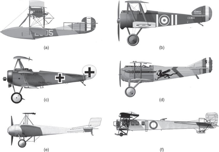
Figure 1.4 Very early aircraft (World War I). (a) Curtiss F4 (USA) , (b) Fokker Dr1 (Germany) , (c) Caproni Ca.20 (Italy), , (d) Sopwith Camel (UK) , (e) SPAD S VII (France) , (f) Sikorsky Ilya Muromets (Bomber).
Source: Courtesy of: www.aviastar.org/air/russia
Source: Courtesy of: www.greatwarflyingmuseum.com
Source: Courtesy of: www.worldac.de
Source: Courtesy of : www.airlinepicture.blogspot.com
Source: Courtesy of: www.fokkerdr1.com
Source: Courtesy of: www.wp.scn.ru
Table 1.1 Performance summary of the aircraft in Figure 1.4.
| Curtiss | Sopwith | Fokker | SPAD | Caproni | Ilya | |
| Flying boat | Camel | DR1 | SVII | Ca20 | Mouromet | |
| Engine‐HP | 2 × 275 | 130 | 110 | 150 | 110 | 4 × 148 |
| Wing area‐ft2 | 1216 | 231 | 201 | 192 | 144 | 1350 |
| MTOM‐lb | 10 650 | 1455 | 1292 | 1632 | ≈1290 | 12 000 |
| Max. Speed‐knot | 85 | 115 | 185 | 119 | 100 | 110 |
In the UK: Upon the recommendation of British Defence Ministry in 1911, the Royal Flying Corps (RFC) was formed in 1912. In 1918 it merged with the Royal Naval Air Service to form the Royal Air Force (RAF). The Royal Aircraft Factory B.E.2 was a single‐engine two‐seat biplane, in service with the RFC in 1912. They were used as fighters, interceptors, light bombers, trainers and reconnaissance aircraft. A more successful design with better capabilities was the single‐seat Sopwith Pup. It entered service in the autumn of 1916. The Avro 504 (100–130 hp) and Sopwith Camel (1913; 110 hp, see Figure 1.4) are some of the well‐known aircraft of their time. Some other famous UK aircraft of the time bore the names of Armstrong‐Whitworth, A.V. Roe, Blackburn, Bristol, Boulton/Paul, De Havilland, Fairey, Handley Page, Short Brothers, Supermarine, Vickers, Westland and so on.
In Germany: Die Fliegertruppen des deutschen Kaiserreiches (the Flier Troops of the German Kaiser Empire), of the Imperial German Army Air Service was formed in 1910 and changed the name to the Luftstretkräfte in 1916 (this became the Luftwaffe in the mid‐1930s). Advances made by the German aeronautical science and technologies produced many types of relatively high‐performance aircraft of the time. These saw action during World War I. The triplane Fokker Dr1 (Figure 1.4) was perhaps the most famous fighter of the period. The triplane was flown by the famous ‘Red Baron’, Rittmeister Manfred Freiherr von Richthofen, the top‐scoring ace of World War 1 with 80 confirmed kills. Another successful German military aeroplane, the Albatross III, served on the Western Front until the end of 1917. The Junkers D.I was the first ever cantilever monoplane design to enter production. It utilised corrugated metal wings and front fuselage with fabric covering only being used on the rear fuselage. The Friedrichshafen FF.33 was one of the earliest German single‐engine amphibious reconnaissance biplanes (1914). Some of the other famous German aircraft of the time bore the names of AEG, Aviatik, DFW, Fokker, Gotha (Gothaer Waggonfabrik), Halberstadt, Hannoversche, Junkers, Kondor, Roland, LVG, Zeppelin and so on.
In France: The French Air Force (Armée de l'Air, ALA) is the air force of the French Armed Forces. It was formed in 1909 as the Service Aéronautique, as part of the French Army, and was made an independent military branch in 1933. The first Bleriot XIs entered military service in France in 1910. Other famous French military aircraft are Nieuport 10 (1914–80 HP France) and their subsequent designs, The SPAD S VII (Figure 1.4) was a successful French fighter aircraft of the First World War used by many countries. The Caudron G.4 series was the first French built twin‐engine bomber biplane platform introduced in the early years of World War 1. Some of the other famous French aircraft of the time bore the names of Hanriot, Maurice Farman, Moraine‐Saulnier, Salmson and so on. Many countries, for example the UK, the USA, Italy and Russia, bought French military aircraft for their Air Force.
Other European Countries: Aircraft design and manufacturing activities in other European countries – for example, Italy, Russia, Scandinavian countries, the countries of the Iberian Peninsular and so on – were also vigorously pursued. Only Italian and Russian designs are briefly given next.
Italy could claim to be among the earliest to experiment with military aviation. As early as 1884 before powered heavier‐than‐air vehicles, the Regio Esercito (Italian Royal Army) operated balloons as observation platforms. During early World War I period Caproni developed a series of successful heavy bombers. The Caproni Ca. 20 (1914) was one of the first real fighter planes (Figure 1.4). It is a monoplane that integrated a movable, forward‐firing drum‐fed Lewis machine gun 2 ft above the pilot's head, firing over the propeller arc. Some of the other famous Italian aircraft of the time bore the names of Società Italiana Aviazione, Ansaldo and so on.
The Russian Empire under Czar had the Imperial Russian Air Force possibly before 1910. Russian aeronautical sciences had advanced research of the time with the famous names like Tsiolkovsky and Zhukovsky. The history of military aircraft in Imperial Russia is closely associated with the name of Igor Sikorsky. He immigrated to the USA in 1919; aircraft bearing his name are still produced. In 1913–14 Sikorsky built the first four‐engine biplane, the Russky Vityaz. His famous bomber aircraft, the Ilya Muromets is shown in Figure 1.4. Other famous aircraft of Russian origin of the time had the names Anade, Antara, Anadwa, Grigorvich and so on.
1.2.5 Period between World War I and World War II – Inter War Period, the Golden Age (1918–1939)
Urgent necessity for military activities during World War I advanced the aeronautical science and technology to the point when post World War I could exploit its potential by presenting attractive proposition for business growth. The aeronautical activities in the peace period were deployed to expand industrial and national growth. The enhanced understanding of aerodynamic, aircraft control laws, thermodynamics, metallurgy, structural and system analyses made aircraft and engine size and performance to grow in rapid strides. A wide variety of innovative new designs emerged to cover wide grounds of application both in military and civil operations. Records for speed, altitude and payload capabilities kept updated in frequent intervals. This period is seen as the Golden Age of aeronautics and reinforced the foundation of the growth led to the present advancement.
With enhanced aeronautical knowledge to increase aircraft capabilities, availability of experienced pilots and public awareness offered ideal environment to make commercial aviation a reality. Surplus post war experienced pilots was available who could easily adapt to newer designs. They kept them engaged with performing in air shows and offers joy rides. In this period, aircraft industries geared up in defence applications and in civil aviation, with financial gain as the clear driver. The free market economy of the West contributed much to aviation progress; its downside, possibly reflecting greed, was under‐regulation. The proliferation showed signs of compromise with safety issues, and national regulatory agencies quickly stepped in, legislating for mandatory compliance with airworthiness requirements (USA – 1926). Today, every nation has its own regulatory agency.
One of the earliest application of commercial operation with passenger flying was done on the modified Sikorsky Ilya Muromets (Bomber – Figure 1.4). It had an insulated cabin with heating and lighting, comfortable seats, lounge and a toilet. Fokker was a Dutch aircraft manufacturer named after its founder, Anthony Fokker. The company operated under several different names, starting out in 1912 in Schwerin, Germany, moving to the Netherlands in 1919. In the 1920s, Fokker entered its glory years, becoming the world's largest aircraft manufacturer. Its greatest success was the F.VIIa/3m trimotor passenger aircraft, which was used by 54 airline companies worldwide. It shared the European market with the Junkers all‐metal aircraft but dominated the American market until the arrival of the Ford Trimotor that copied the aerodynamic features of the Fokker F.VII, and Junkers structural concepts. In May 1927, Charles Lindberg won the Ortega prize for the first individual non‐stop transatlantic flight.
Early aircraft design was centred on available engines, and the size of the aircraft depended on the use of multiple engines. The combination of engines, materials, and aerodynamic technology enabled aircraft speeds of approximately 200 mph; altitude was limited by human physiology. In the 1930s, Durener Metallwerke of Germany introduced duralumin, with higher strength‐to‐weight ratios of isotropic material properties, and dramatic increases in speed and altitude resulted.
1.2.6 World War II (1939–1945)
The introduction of duralumin brought a new dimension to manufacturing technology. Structure, aerodynamics and engine development paved the way for substantial gains in speed, altitude and manoeuvring capabilities. These improvements were seen pre‐eminently in World War II designs such as the Supermarine Spitfire, the North American P‐51, the Focke‐Wolfe 190 and the Mitsubishi Jeero‐Sen. Multiengine aircraft also grew to sizes never before seen.
The invention of the jet engine (independently by Whittle of the United Kingdom and von Ohain of Germany) realised the potential for unheard‐of leaps in speed and altitude, resulting in parallel improvements in aerodynamics, materials, structures and systems engineering. Heinkel He 178 is the first jet powered aircraft (27 August, 1939), followed by the Gloster E.28 on 15 May, 1941.
1.2.7 Post‐World War II
A better understanding of supersonic flow and a suitable rocket engine made it possible for Chuck Yeager to break the sound barrier in a Bell X1 in 1949 (the aircraft is on exhibit at the Smithsonian Air and Space Museum in Washington, D.C). Tens of thousands of the Douglas C‐47 Dakota and Boeing B17 Flying Fortress were produced. Post‐war, the De Havilland Comet was the first commercial jet aircraft in service; however, plagued by several tragic crashes, it failed to become the financial success it promised.
The 1960s and 1970s saw rapid progress with many new commercial and military aircraft designs boasting ever‐increasing speed, altitude and payload capabilities. Scientists made considerable gains in understanding the relevant branches of nature: in aerodynamic [4] issues concerning high lift and transonic drag; in materials and metallurgy, improving the structural integrity; and in significant discoveries in solid‐state physics. Some of the outstanding designs of those decades emerged from the Lockheed Company, including the F104 Starfighter, the U2 high‐altitude reconnaissance aircraft and the SR71 Blackbird. These three aircraft, each holding a world record of some type, were designed in Lockheed's Skunk Works, under the supervision of Clarence (Kelly) Johnson. I recommend that readers study the design of the nearly half‐century‐old SR71, which still holds the speed–altitude record for aircraft powered by air‐breathing engines.
During the late 1960s, the modular approach to gas‐turbine technology gave aircraft designers the opportunity to match aircraft requirements (i.e. mission specifications and economic considerations) with ‘rubberised’ engines (vide Section 12.2). This was an important departure from the 1920s and 1930s, when aircraft sizing was based around multiples of fixed‐size engines. Chapter 12 describes the benefits of modular engine design. This advancement resulted in the development of families of shorter and longer aircraft designs. Plugging the fuselage sections and, if necessary, allowing wing growth covered a wider market area at a lower development cost because considerable component commonality could be retained in a family: a cost‐reduction design strategy. Capitalistic objectives render designers quite conservative, forcing them to devote considerably more time to analysis. Military designs emerge from more extensive analysis – for example, the strange‐looking Lockheed F117 is configured using stealth features to minimise radar signature. Now, more matured stealth designs look conventional (e.g. the Lockheed F22).
1.3 Aircraft Evolution
Figure 1.5 shows the history of progress in speed and altitude capabilities. The impressive growth in one century is astounding – leaving the Earth's surface in a heavier‐than‐air vehicle and returning from the Moon in fewer than 66 years!
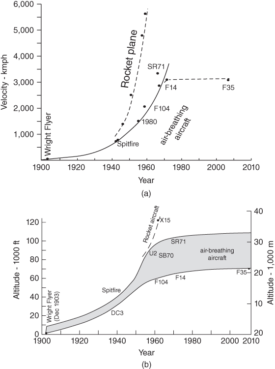
Figure 1.5 Aircraft operational envelope. (a) Speed and (b) altitude.
It is interesting that for air‐breathing engine powered aircraft, the speed–altitude record is still held by the more than 40‐year‐old design, the SR71 (Blackbird), capable of operating at around Mach 3.0 and a 100 000‐ft altitude. Aluminium‐alloy properties would allow a flight speed up to Mach 2.5. Above Mach 2.5, a change in material and/or cooling would be required because the stagnation temperature would approach 600 K, exceeding the strength limit of aluminium alloys. Aircraft speed–altitude capabilities have remained stagnant since the 1960s. A recent breakthrough was the success of Spaceship One that took aircraft to the atmosphere edge to 100 km altitude. In civil aviation, the supersonic transport (SST) aircraft Concorde was designed nearly four decades ago and has not yet been supplanted. Concorde's speed–altitude capability is Mach 2.2 at around 60 000 ft.
In military aircraft scenarios, gone (almost) are the days of ‘dogfights’ that demanded a high‐speed chase to bring an adversary within machine‐gun firing range (i.e. low projectile speed, low impact energy, and no homing); if the target was missed, the hunter became the hunted. In the post‐World War II period, around the late 1960s, air‐superiority combat required fast acceleration and speed (e.g. the Lockheed F104 Starfighter) to engage with infrared homing missiles firing at a relatively short distance from the target. As missile capabilities advanced, the current combat aircraft design trend showed a decrease in speed capabilities. Instead, high turning rates and acceleration, integrated with superior missile capabilities (i.e. guided, high speed and high impact even when detonated in proximity of the target), comprise the current trend. Target acquisition beyond visual range (BVR) – using an advance warning system from a separate platform – and rapid aiming comprise the combat rules for mission accomplishment and survivability. Current military aircraft operate below Mach 2.5; hypersonic aircraft are in the offing.
1.3.1 Aircraft Classifications and their Operational Environments
There are many types of aircraft in production serving different sectors of mission requirements; civil and military missions differ substantially. It is important to classify aircraft category to isolate and identify strong trends existing within a class. An aircraft can be classified based on its role, use, mission, power plants and so forth, as shown in Table 1.2. Here, the first level of classification is based on operational role (i.e. civil or military discussion on military aircraft is given online) and this chapter is divided into these two classes. In the second level, the classification is based on the generic mission role, which also would indicate size. The third level proceeds with classification based on the type of power plant used and so on. The examples worked out in this book are the types that cover a wide range of aircraft design, which provides an adequate selection for an aircraft design course.
Table 1.2 Aircraft classification.
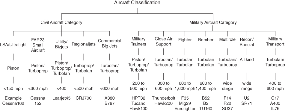 |
Readers are suggested to examine what could be the emerging design trends within the class of aircraft. In general, new commercial aircraft designs are extensions of the existing designs incorporating proven newer technologies (some are fallouts from declassified military applications) in a very conservative manner.
Figure 1.6 indicates the speed–altitude regimes for the type of power plant used. Currently, low‐speed–low‐altitude aircraft are small and invariably powered by piston engines of no more than 500 horsepower (HP) per engine (turboprop engines start to compete with piston engines above 400 HP). World War II had the Spitfire aircraft powered by Rolls Royce Merlin piston engines (later by Griffon piston engines) that exceeded 1000 HP; these are nearly extinct, surviving only in museum collections. Moreover, aviation gasoline (AVGAS) for piston engines is expensive and in short supply.

Figure 1.6 Engine selections for the speed–altitude capabilities.
The next level in speed–altitude is by turboprops operating at shorter ranges (i.e. civil aircraft application) and not critical to time due to a slower speed (i.e. propeller limitation). Turboprop fuel economy is best in the gas‐turbine family of engines. Subsonic cargo aircraft and military transport aircraft may be more economical to run using turboprops because the question of time is less critical, unlike passenger operation that is more time critical with regard to reaching their destinations.
The next level is turbofans operating at higher subsonic speeds. Turbofans (i.e. bypass turbojets) begin to compete with turboprops at ranges of more than 1000 nm due to time saved as a consequence of higher flight speed. Fuel is not the only factor contributing to cost – time is also money. A combat aircraft power plant uses lower bypass turbofans; in earlier days, there were straight‐through (i.e. no bypass) turbojets. Engines are discussed in more detail in Chapters 12 and 13.
Figure 1.7a illustrates the thrust‐to‐weight ratio of various types of engines. Figure 1.7b illustrates the specific fuel consumption (sfc) at sea level static takeoff thrust (TSLS) rating in an International Standard Atmosphere (ISA) day for various classes of current engines. At cruise speed, the sfc would be higher.
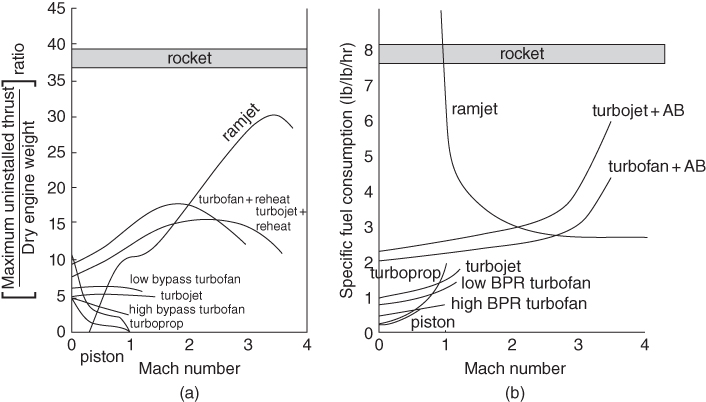
Figure 1.7 Engine performance. (a) Thrust to weight ratio and (b) specific fuel consumption (modified from the diagrams of Harned, M., Aero Digest, Vol, 69, No. 1, July, 1954.
1.4 Current Aircraft Design Trends for both Civil and Military Aircraft (the 1980s Onwards)
Aircraft design is affected by a number of issues not the least is the economic considerations for the product whether civilian or military. The current aircraft design trends for civil and military aircraft are discussed separately in the following two sub‐sections.
A major concern that emerged in the commercial aircraft industry from the market trend and forecast analysis of the 1990s was the effect of inflation on aircraft manufacturing costs. Since then, all the major manufacturers and the subcontracting industries have implemented cost‐cutting measures. As many more factors have become more important, the conceptual phase of aircraft design is now conducted using a multidisciplinary approach (i.e. concurrent engineering), which must include manufacturing engineering and an appreciation for the cost implications of early decisions; the buzzword is integrated product and process development (IPPD). Margins of error have shrunk to the so‐called zero tolerance so that tasks are done right the first time. Two of the management tools to achieve this end are (i) Design for Manufacture and Assembly (DFM/A), an engineering approach with the objectivity to minimise cost of production without sacrificing design integrity and (ii) Design for Six‐Sigma (DFSS); an integrated approach to design with the key issue to reduce any scope for mistakes/inefficiencies, that is, make the product right the first time to prevent waste of company resources. The importance of environmental issues emerged, forcing regulatory authorities to impose limits on noise and engine emission levels. Recent terrorist activities are forcing the industry and operators to consider preventive design features. Also, the consideration for better on‐board medical attention is always there.
With rising fuel prices, air travellers have become cost‐sensitive. In commercial aircraft operations, the direct operating cost (DOC) depends more on the acquisition cost (i.e. unit price) than on the fuel cost (2000 prices) consumed for the mission profile. Today, for the majority of mission profiles, fuel consumption constitutes between 15 and 25% of the DOC (DOC, see Section 16.3), whereas the aircraft unit price contributes between three and four times as much, depending on the payload range [5]. For this reason, manufacturing considerations that can lower the cost of aircraft production should receive as much attention as the aerodynamic saving of drag counts. The situation would change if the cost of fuel exceeds the current airfare sustainability limit (see Section 1.7 and Chapter 16). The price of fuel in 2008 was approaching the limit when drag‐reduction efforts were regaining ground.
The last three decades witnessed a 56% average annual growth in air travel, exceeding 2 × 10⁹ revenue passenger miles (RPM) per year. Publications by the International Civil Aviation Organization (ICAO), National Business Aviation Association (NBAA) and other journals provide overviews of civil aviation economics and management. The potential market for commercial aircraft sales is on the order of billions of dollars per year. However, the demand for air travel is cyclical and – given that it takes about 4 years from the introduction of a new aircraft design to market – operators must be cautious in their approach to new acquisitions: They do not want new aircraft to join their fleet during a downturn in the air travel market. Needless to say, market analysis is important for both the manufacturers and operators in planning new projects and purchases.
Deregulation of airfares has made airlines compete more fiercely in their quest for survival. The growth of budget airlines compared to the decline of established airlines is another challenge for operators.
It became clear that the current design trends for civil aircraft is customer‐driven strategy as the best approach for survival in a fiercely competitive marketplace. The new paradigm of ‘better, farther and cheaper to market’ replaced, in a way, the old mantra of ‘higher, faster and farther’ [5].
Readers are suggested to examine what could be the emerging design trends within the class of aircraft. In general, new commercial aircraft designs are extensions of existing designs incorporating proven newer technologies (some are fallouts from declassified military applications) in a very conservative manner. It is seen as working in verified design space, that is, incorporating proven but advanced technologies.
The military aircraft has priority of national defence interest over commercial considerations. To stay ahead of any potential adversary, the research and design organisations constantly search for new technologies never tried before. Although these new technologies are required to be demonstrated satisfactorily before implementation, these are yet to be proven in operational arena. On account of these unknown factors, it is seen as working in an aspirational design space.
While commercial aircraft can earn self‐sustaining revenue, military operations depend totally on government expenditures with limited potential for continuing revenue beyond the occasional cash from approved export sales. The cost of developing and building a new design has risen sufficiently to strain the economy of most single nations. Not surprisingly, the number of new designs proposals has drastically reduced, with military designs moving towards multinational collaborations among allied nations. The retention of confidentiality in defence matters is an additional complicating factor.
Combat roles are classified as interdiction, air‐superiority, air defence and, when missions overlap, multi‐role (see Section 10.4 for details). Action in hostile environments calls for special attention to: design for survivability; systems integration for target acquisition and weapons management; and design considerations for reliable navigation and communication. All told, it is a complex system – mostly operated by a single pilot – an inhuman task unless the workload were relieved by microprocessor‐based decision making. Fighter pilots are special breed of aircraft operators demanding the best emotional and physical conditioning to cope with the stresses involved. Aircraft designers have deep obligation to ensure combat pilot survival. Unmanned Aerial Vehicle (UAV) technology is in the offing – the Middle‐East conflict saw the successful use of UAVs both for surveillance and military operations.
1.4.1 Current Civil Aircraft Trends
When Boeing introduced its 737 twinjet aircraft (derived from their then best‐selling three‐engine B727,), the DouglasDC‐9 and BAe 111 were the most popular two‐engine commercial transport aircraft. The Boeing737 series, spanning nearly four decades of production to this day, has become the best‐selling aeroplane in the history of the commercial aircraft market with more than 10 000 shipped and ordered. Of course, in that time, considerable technological advancements have been incorporated, improving the B737's economic performance at least by about 50%.
Current commercial transport aircraft in the 100–300‐passenger classes all have a single slender fuselage, backward‐swept low‐mounted wings, two under‐slung wing‐mounted engines, and a conventional empennage (i.e. a horizontal and a vertical tail); this conservative approach is revealed in the similarity of configuration. The similarity in larger aircraft is the two additional engines; there have been three‐engine designs but only on a few aircraft because the configuration was rendered redundant by variant engine sizes that cover the in‐between sizes and extended twin operations (ETOPS). The largest commercial‐jet‐transport aircraft, the Airbus380 (Figure 1.8a) made its first flight on 27 April, 2005 and is currently in service. Boeing87 Dreamliner (Figure 1.8b) is the replacement for its successful Boeing 767 and 777 series, entered service on January, 2011 aiming at competitive economic performance. The new addition is the Airbus350, slightly larger than B787, entered service on January, 2015.
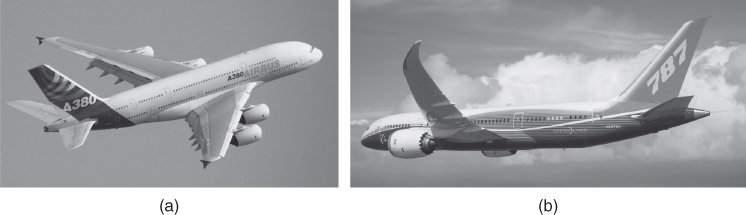
Figure 1.8 Current wide‐body large commercial transport aircraft. (a) Airbus380 (Courtesy of Airbus) and (b) Boeing787 Dreamliner.
Source: Copyright: Boeing.
The gas‐turbine turboprop engine offers better fuel economy than to current turbofan jet engines. However, because of propeller limitations, the turboprop‐powered aircraft's cruise speed is limited to about two‐thirds of the high‐speed subsonic turbofan‐powered aircraft. Operators have to consider that at lower operational ranges (e.g. distances less than 1000 nautical miles [nm]) the difference in sortie time would generally be less than a half hour, with an approximate 20% saving in fuel cost. If a long‐range time delay can be tolerated (e.g. for cargo or military heavy‐lift logistics), then large turboprop aircraft operating over longer ranges become more economical. Advances in propeller technology are pushing turboprop‐powered aircraft cruise speeds close to the high subsonic cruising speed of turbofan‐powered aircraft high subsonic cruise speeds.
1.4.2 Current Military Aircraft Trends
There are differences between civil and military design requirements (see Section 1.9.1). However, there are some similarities in their design processes up to the point when a new breakthrough is introduced – one thinks instinctively of how the jet engine changed designs in the 1940s. Consider the F117 Nighthawk (Figure 1.9): in order to incorporate stealth technology appeared as an aerodynamicist's nightmare; but it too is now conforming to something familiar in the shape of the F35 lightening II; its prototype X35 is given in Figure 1.9. We must not forget that military roles are more than just combat: they extend to transportation and surveillance (reconnaissance, intelligence gathering and electronic warfare). The F35, Eurofighter, Rafale, Gripen, Sukhoi PAK‐FA and so on, are the current frontline fighter aircraft. In strategic bombing B52 served for four decades and is to continue for another two decades – some design! The latest B2 (Figure 1.9) bomber looks like an advanced flying wing without the vertical tail.

Figure 1.9 Current combat aircraft. (a) F117 Nighthawk. , (b) X‐35 (F35 experimental) and (c) B2 Bomber..
Source: courtesy of U.S Airforce/Sgt Jeremy Wilson
Source: courtesy of the U.S Airforce/Dana Russo
Source: Courtesy of the U.S Airforce/Sgt Aaron Allmon
1.5 Future Trends
It is no exception from past trends that speed, altitude and payload will be expanded in both civilian and military capabilities. Coverage on the aircraft design process in the next few decades is given in [1, 3]. In the near‐future trends the vehicle‐capability boundaries will be pushed to the extent permitted by economic and defence factors and infrastructure requirements (e.g. navigation, ground handling, support etc.). Section 1.7 gives a short list of new technologies currently under investigation. In technology, smart material (e.g. adaptive structure) will gain ground, microprocessor‐based systems will advance to reduce weight and improve functionality and manufacturing methodology will become digital. However, unless the price of fuel increases beyond affordability, investment in aerodynamic improvement will be next in priority. Small flyers and unmanned aircraft are emerging as new markets. Readers are advised to make periodic search on various web sites and journals for updated information on this topic.
Future designs consist of the Smarter Skies vision studying concepts to reduce waste in the system (waste in time, waste in fuel and reduction of CO2). The European Union's NACRE (New Aircraft Concepts Research) project is studying potential radical overhauls to aircraft design with the goal of improving eco‐efficiency, optimising performance and reducing costs. Within this effort, the NACRE Pro Green aircraft specifically aims at the reduction of an airliner's operational environmental footprint.
Compared to current‐generation aircraft, the design for ultra‐low emissions will cause some limitations in operational aspects. The slow cruise speed would reduce the number of flights per day and thus affect its economic productivity, with a passenger's overall travelling time increasing by between 5 and 10%. The high precision surfaces for the laminar flow wing could require special treatment and care in the manufacturing process. Likewise, the engine position on top of the fuselage is expected to require specific attention and increased effort during maintenance, compared to under‐wing installations.
In the military scenario, it is the electronics that would play the main role, although aerodynamic challenges on stealth, manoeuvre and improved capability/efficiency would be as much as in demand as would be for structural/material considerations. Engine development would also be in parallel development with all of these discoveries/inventions.
Fighter aircraft systems will have enhanced capabilities in areas such as reach, persistence, survivability, net‐centricity, situational awareness, human‐system integration and weapons effects. The future system will have to counter adversaries equipped with next‐generation advanced electronic attack, sophisticated integrated air defence systems, passive detection, integrated self‐protection, directed energy weapons and cyberattack capabilities. In the immediate future, fighters are expected to use advanced engines such as Adaptive Versatile Engine Technology to allow longer ranges and higher performance.
Both operators and manufacturers will be alarmed if the price of fuel continues to rise to a point where the air‐transportation business finds it difficult to maintain profitable operations. It is likely that demand for power plants using alternative fuels, biofuel, liquid hydrogen (LOH) and possibly nuclear power for large transport aircraft covering long ranges. Aircraft fuelled by LOH have been used in experimental flight for some time, and fossil fuel mixed with biofuel is currently being flight tested especially with the US military's biofuel initiative.
Long‐distance hypersonic attack aircraft represent a strong candidate for short‐time deployment strike aircraft. Again, it is the electronics that plays the main role, although aerodynamic challenges of stealth manoeuvre, and improved capability/efficiency are also in as much demand for structural/material considerations. Engine development is also in parallel development with all of these discoveries/inventions.
This book does not deal with these futuristic designs. One must first master the fundamentals presented in this book to carry out such futuristic designs. If enough information is available, then these futuristic military aircraft could be more suited material for postgraduate teamwork on aircraft design, undertaken by those who already have some proficiency in aeronautical engineering and have the time for longer project work. Without systems integration and matched weapon integration for the mission role, mere aerodynamic shaping and a list of weaponry wish list exercises would prove meaningless. Representative details of systems architecture and their capabilities affecting aircraft performance are still not fully available in the public domain. Working on such an important aspect based on piecemeal information is not the best procedure to attempt in the undergraduate curriculum when there is so much to learn from conventional designs. Chapter 21 briefly covers miscellaneous design considerations.
1.5.1 Civil Aircraft Design
Any extension in payload capacity will remain subsonic for the foreseeable future until gains made by higher speed vehicles demonstrate operational success. High‐capacity operations will likely remain around the size of the Airbus 380.
Some carefully modelled and researched futuristic designs seen in Figure 1.10 have the potential to remarkably increase capacity. A blended‐wing body (BWB-B2) can use the benefits of the wing‐root thickness sufficiently large to permit merging (Figure 1.10a, top – NASA green aircraft goals) with the fuselage, thereby benefiting from the fuselage's contribution to lift and additional cabin volume. Another alternative seen in Figure 1.10a, bottom would be that of the joined‐wing concept. Studies of twin‐fuselage and joined‐fuselage large transport aircraft are given in Figure 1.10b and show additional potential. In the conventional design, although yet to be realised, there is no reason why an over‐wing nacelle pod (Figure 1.10c) mounted large capacity commercial aircraft configuration not to succeed in operation. The concept is not new. The VFW 614 aircraft with over‐wing pods were produced in the 1970s. The Hondajet with an over‐wing nacelle is currently going through the Federal Aviation Administration (FAA) certification process.
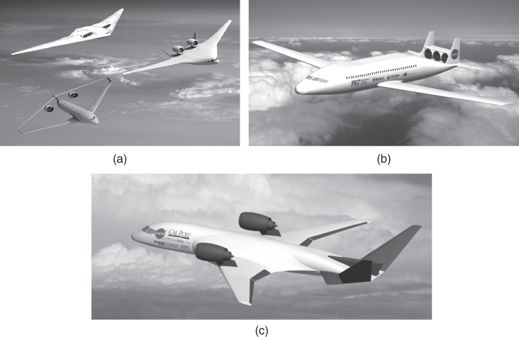
Figure 1.10 Some well‐studied futuristic subsonic aircraft designs. (a) Blended‐wing aircraft (top) and joined wing (bottom), (b) joined fuselage and (c) over‐wing nacelle. Credit: Massachusetts Institute of Technology..
Source: all photos courtesy of Courtesy of NASA
The speed–altitude extension will progress initially through SSTs and then hypersonic transport (HST) vehicles. The SST technology is well understood after three decades of studying the performance of the Anglo–French‐designed Concorde, which was designed to operate above Mach 2 at a 50 000‐ft altitude carrying 128 passengers.
Contemporary planning for the next‐generation SST suggests similar speed–altitude capability but with sizes varying from as few as 10 business passengers to approximately 300 passengers in at least transatlantic and transcontinental operations. Transcontinental operations will demand sonic‐shock‐strength reduction through aerodynamic gains because operating at anything less than Mach 1.6 has less to offer in terms of time savings.
The next‐generation SST will have about the same speed–altitude capability (possibly less in speed capability, around Mach 1.8), but the size will vary from as few as 10 business passengers (Figure 1.11a) to approximately 300 passengers (Figure 1.11b) to cover at least transatlantic and transcontinental operations. Transcontinental operations would demand sonic‐shock‐strength reduction through aerodynamic gains rather than speed reduction; anything less than Mach 1.6 has less to offer in terms of time savings.
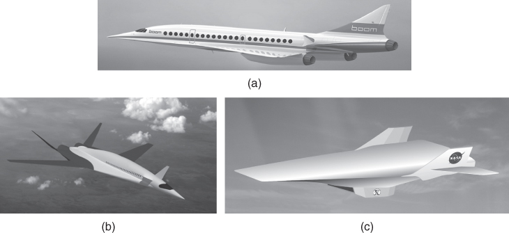
Figure 1.11 Some well‐studied futuristic supersonic/hypersonic aircraft designs. (a) Small supersonic transport aircraft. . (b) Large supersonic transport aircraft..
(c) Hypersonic aircraft. Source: Credit: NASA, USA
Source: Credit: Boom Technology, USA
The real challenge will be to develop an hypersonic transport aircraft (HST) (Figure 1.11c) operating at approximately Mach 6 that would require operational altitudes above 100 000 ft. Speed above Mach 6 offers diminishing returns in time saved because the longest distance necessary is only about 12 000 nm (i.e. about 3 hours of flight time).
Smaller Bizjets and regional jets will morph, and unfamiliar shapes may appear on the horizon, but small aircraft in personal ownership used for utility and pleasure flying are likely to revolutionise the concept of flying through their popularity, similar to how the automobile sector grew. The revolution will occur in short‐field capabilities, as well as vertical takeoffs, and safety issues in both design and operation. Smaller aircraft used for business purposes will see more private ownership to stay independent of the more cumbersome airline operations. There is a good potential for airparks to grow. Various ‘roadable’ aircraft (flying car) have been designed. The major changes would be in system architecture through miniaturisation, automation and safety issues for all types of aircraft.
The NASA, the US Department of Transportation (USDOT), FAA, industry stakeholders and academia have joined forces to pursue a National General Aviation Roadmap leading to a Small Aircraft Transportation System (SATS). This strategic undertaking has a 25‐year goal to bring the next generation of technologies to and improve travel between remote communities and transportation centres in urban areas by utilising the nation's 5400 public use general aviation airports (United States). The density of these airfields in Europe is much higher. The major changes would be in system architecture through miniaturisation, automation and safety issues for all types of aircraft.
A new type of vehicle known as a ground‐effect vehicle (GEV) is a strong candidate for carrying a large payload (e.g. twice that of the Boeing 747) and flying close to the surface, almost exclusively over water. (A GEV is not really new: The Russians built a similar vehicle (Figure 1.12) called the ‘Ekranoplan’, but it did not appear in the free market economy.). It operated around 350 mph with undeniable future potential.
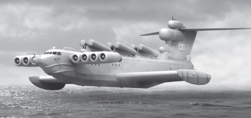
Figure 1.12 Lun class Ekranoplan (https://en.wikipedia.org/wiki/Lun‐class_ekranoplan).
1.5.2 Military Aircraft Design
Progress in military would defy all imaginations (readers may also research this on the Internet). Size and shape could be as small as an insect for surveillance to as large as any existing kind. Vehicles as small as 15 cm and of a 1 kg mass have been successfully built for operation. Prototypes much smaller are already successfully flown. Reliance on in‐built intelligence would certainly lead to more remotely piloted vehicles (RPV) in operation. Other terminologies include unmanned, unoccupied, pilotless – it is better that I settle with one term – I call this RPV. These are piloted remotely or autonomously. However, the Unmanned or Unoccupied Air Vehicle (UAV) is also a prevalent terminology. I saw in literature ‘unoccupied micro‐vehicle’ – wondering who would be the possible occupant, otherwise?
It is the electronics that would play the main role, although aerodynamic challenges on stealth, manoeuvre and improved capability/efficiency would be as much in demand as would structural/material considerations. Engine development would also be in parallel to all of these discoveries/inventions.
Long‐distance hypersonic attack aircraft represent strong candidates for short‐time deployment strike aircraft. Again, it is the electronics that plays the main role, although aerodynamic as mentioned before are also in as much demand and engine development is parallel development to these. Military applications for HST vehicles are likely to precede civilian applications. Small‐scale HST vehicles have been flown recently.
In the military scenario, the USAF seeks Next‐Generation Tactical Aircraft/Next Gen TACAIR. In the immediate future, the sixth‐generation fighters are expected to use advanced engines. The long‐range strike systems are seen in the form of the Long‐Range Strike Bomber (LRS‐B), currently under study in the USA. Russia is also developing a new long‐range bomber called the PAK‐DA, with a BWB that has an outer wing section with swing wing capability.
Once again it is electronics, aerodynamics, structural/material considerations and engine development would also develop further.
1.5.3 UAVs/UASs
The UAVs are powered, aerial vehicles flown without a human pilot on board. They have had many names, previously known as drones and subsequently have had names, for example, RPVs, unpiloted aerial vehicles (UAVs), remotely piloted aircraft (RPAs) and so on. In 2005, a designated name unmanned aircraft system (UAS) was introduced that has been now accepted for use by the US DOD, FAA, CAA and ICAO. This book uses the synonymous terms of UAV and UAS interchangeably.
The concept of a drone is not new; as early as World War I (WWI), they were deployed. WWII saw their extensive usage. Since the 1950s and the advent of transistors, by using hand held controllers, recreation model aircraft flying became popular. Subsequently, with microprocessor‐based on‐board instrumentation, military usage of UASs has been successfully demonstrated. Nations who can afford the technology have already entered the race to develop UAVs/UASs.
While this book does not deal with UAV designs, there exits considerable similarity in aerodynamic and propulsive design considerations. The difference is in the type of electronic payload carried on board. Hence, UAVs are briefly introduced here so that the readers may take an interest if they wish to specialise; UAVs are normally offered in separate courses involving systems integration to specific types of UAV applications. UAVs are often preferred for missions that are too dangerous or in emergencies for manned aircraft.
The general approach to configure the external geometry during conceptual design phase (Phase I) follows the same route as dealt with in this book, bearing in mind the need to cater for the laid down mission specifications, for example, payload and range/endurance and manoeuvre limits. The aerodynamic, structure and propulsive design considerations adopt a similar methodology to satisfy the requirements. Being without any occupant, the certification standards are different and in certain areas less stringent. Cost factors also allows to search for cost effective, material, systems and power plant specifically meant for UAV/UAS.
UASs fall under two categories as follows:
- Autonomous – Aircraft with the ability to make decisions without human intervention. These are mostly used in military applications as missiles, as target for training aircraft gunners and so on. These are not suitable for civilian usage and seen unsuitable for regulation due to legal and liability issues.
- Remotely piloted with a human interface for decision making. These can be both of military and civil types. With proliferation in civil applications, for safety reasons, the UAS are now subjected to government regulations of the respective countries.
There are many types of usages, broadly falling under the following categories.
1.5.4 Military Applications
Pilot survivability constraints are being taken out of the design process as system‐processing power grows. In the future, remote‐controlled or pilotless aircraft will have the advanced computer capability to make weapon delivery decisions and advanced accuracy that could eliminate an on‐board human interface thus permitting the aircraft to operate with greater loads and improved combat capability. More RPVs are anticipated to come into operation. Military UAV/UAS have the following applications:
- Combat – To providing attack capability for high‐risk missions. Capable of very high‐g rapid turning for tactical gains, very low altitude flying for stealth and others specific to mission requirements that are beyond the capabilities of manned aircraft.
- Reconnaissance – To gather intelligence for defence usage.
- Logistic – Deliver military cargo in high‐risk and accessible areas.
- Target and decoy – To simulate enemy aircraft or missiles for countermeasures and aiming practise.
Progress in military aircraft may defy all our contemporary imaginations. Flyers sized as small as insects (micro aircraft – dragonfly drones 15 cm and 1 kg mass) for surveillance [10]) have been successfully built for operation. Much smaller prototypes are being successfully flown.
1.5.5 Civil and Commercial Applications
These cover a wide of applications to a fast‐growing industry. Some of the application areas by governments include non‐military security work, policing, traffic and crowd monitoring. Reconnaissance operations, border patrol missions, forest fire detection, surveillance, coordinating humanitarian aid, search and rescue missions, detection of illegal human trafficking, illegal hunting, land surveying, fire and large‐accident investigation, landslide measurement, illegal landfill detection, firefighting, such as inspection of power or pipelines and so on.
Usage by private business sector and individuals include aerial surveying of crop search and rescue operations, crop spraying, inspecting power lines and pipelines, counting wildlife, delivering parcel and medical supplies to remote or otherwise inaccessible regions, media, surveillance, recreational (see next), land assessment, filming and so on.
The downsides are the proliferations, unnecessarily invading privacy, accidents causing damage and injuries and so on, for which steps to regulate are gradually evolving in this relatively new application domain.
1.5.6 Recreational Applications
Recreational model flying is allowed to operate below 400 ft in designated areas.
1.5.7 Research and Development Applications
These aim to further develop UAV/UAS technologies. Today, non‐recreational UAV/UAS usage must require certification of authorisation and must be flown by qualified ground‐based pilots. Recreational model flying is allowed to operate below 400 ft in designated areas.
UAS designs have explored helicopter like UAVs with vertical takeoff and landing capabilities. They come in many configurations that include multirotors, for example, quadcopters; hexacopters, octocopters and so on. They also come in many shapes, from small to large heavy lifters. The term Vertical Takeoff and Landing Tactical Unmanned Aerial Vehicle (VTUAV) is used in military applications.
Figure 1.13 shows an operational UAV, the Ikhana, used for imaging. Figure 1.13b shows military UAS configuration types.

Figure 1.13 Future unmanned aircraft system (UAS). (a) Ikhana and (b) X47B Northrop Grumman (https://news.usni.org).
Source: Courtesy of General Aeronautical Systems, Inc.
1.5.8 Rocket Applications in Future Aircraft Design Trends
Von Braun [7] mentions that he took the idea from Tippu's success for his V2 rocket, paving the way for today's achievement in space flight as an expanded envelope beyond winged flight vehicles and originally deemed likely to begin commercial operation by 2012. Rocketry first entered the Western European experience when Tippu Sultan used rockets against the British‐led Indian army at the Battle of Srirangapatna in 1792. The propellants were based on a Chinese formula nearly 1000 years old. The experience of Tippu's rockets led the British to develop missiles at the Royal Laboratory of Woolwich Arsenal, under the supervision of Sir William Congreve, in the late eighteenth century.
A new type of speed–altitude capability will come with suborbital space flight (tourism) using rocket‐powered aircraft, as demonstrated (2004) by designer Burt Rutan's Space Ship One hitch‐hiked to the jet engine powered White Knight aeroplane to suborbital space. Interest in this aircraft has continued to grow – the prize of $10 million offered could be compared with that of a transatlantic prize followed by commercial success. The advent and success of the Rutan‐designed Space Ship One will certainly bring about the large market potential of rocket‐powered aeroplanes.
A larger Space Ship Two is currently being developed. A new type of speed–altitude capability will come from suborbital space flight (tourism) using rocket‐powered aircraft, as demonstrated by Rutan's Space Ship Two that hitchhikes with the White Knight to altitude (Figure 1.14), from where it makes the ascent. Interest in this aircraft has continued to grow – particularly in view of the prixe and potential for success described before.

Figure 1.14 White Knight carrying Space Ship Two. Reproduced with permission of Virgin Atlantic.
There are other contenders to exploit the growing potential of this kind of space tourism.
1.6 Forces and Drivers
The current aircraft design strategy is linked to industrial growth, which in turn depends on national infrastructure, governmental policies, workforce capabilities and natural resources; these are generally related to global economic‐political circumstances. More than any other industry, the aerospace sector is linked to global trends. A survey of any newspaper provides examples of how civil aviation is affected by recession, fuel price increases, spread of infectious diseases and international terrorism. In addition to its importance for national security, the military aircraft sector is a key element in several of the world's largest economies. Indeed, aerospace activities must consider the national infrastructure as an entire system. A skilled labour force is an insufficient condition for success if there is no harmonisation of activity with national policies; the elements of the system must progress in tandem. Because large companies affect regional health, they must share socio‐economic responsibility for the region in which they are located.
The current status stems from the 1980s when returns on investment in classical aeronautical technologies such as aerodynamics, propulsion and structures began to diminish. Around this time, however, advances in microprocessors enabled the miniaturisation of control systems and the development of microprocessor‐based automatic controls (e.g. fly‐by‐wire: FBW), which also had on additional weight‐saving benefit. Dramatic but less ostensive radical changes in aircraft management began to be embedded in design. At the same time, global political issues raised new concerns as economic inflation drove man‐hour rates to a point at which cost‐cutting measures became paramount. In the last three decades of the twentieth century, man‐hour rates in the West rose four to six times (depending on the country), resulting in aircraft price hikes (e.g. typically by about six times for the Boeing 737 – of course, accompanied by improvements in design and operational capabilities.) Lack of economic viability resulted in the collapse or merger/takeover of many well‐known aircraft manufacturers. The number of aircraft companies in Europe and North America shrunk by nearly three‐quarters; currently, only two aircraft companies (Boeing and Airbus, i.e. in the West) are producing large commercial transport aircraft. Bombardier Aerospace and Embraer of Brazil have recently entered the large‐aircraft market with capacity of more than 100 passengers. Also, in the are the Russians, the Chinese and the Japanese. Over time, aircraft operating‐cost terminologies have evolved and, currently, the following are used in this book.
Over time, aircraft operating‐cost terminologies have evolved and currently, the following are used in this book (Section 16.5 gives details).
IOC – Indirect Operating Cost: Comprises Costs not directly involved with the sortie (trip).
COC – Cash Operating Cost: Comprises the trip (sortie) Cost elements.
FOC – Fixed Operating Cost: Comprises Cost elements even when not flying but related to trip cost.
DOC – Direct Operating Cost: = COC + FOC.
TOC – Total Operating Cost: = IOC + DOC.
Because there are variances in definitions, this book uses the standardised definitions.
The importance of environmental issues emerged, forcing regulatory authorities to impose limits on noise and engine emission levels. Of late terrorist activities have made the industry and operators think hard about preventive design considerations.
1.7 Airworthiness Requirements
From the days of barnstorming and stunt flying in the 1910s, it became obvious that commercial interest had the potential to short‐circuit safety considerations. Government agencies quickly stepped in to safeguard people's security and safety without deliberately harming commercial interest. Western countries developed and published thorough systematic rules – these are in the public domain (see relevant websites). In civil applications, they are Federal Aviation Regulation (FAR) (US) and JAR (the newly formed designation is European Aviation Safety Agency – EASA); both are quite close. The author prefers to work with the established FAR at this point. In military applications, the standards are Milspecs (US) and Defence Standard 970 (earlier AvP 970 – UK); they do differ in places.
The Government of United States of America have 50 titles of Code of Federal Regulations (CFRs) published in the Federal Register by the Federal Government covering wide areas subjected to federal regulations. The FARs, are rules prescribed by the FAA governing all aviation activities in the USA under title 14 of the CFRs, which covers wide varieties of aircraft related activities in many parts, of which this book concerns mainly with Parts 23, 25, 33 and 35. However, another set of regulations in Title 48 of CFRs is the ‘Federal Acquisitions Regulations’, and this has led to confusion with the use of the acronym ‘FAR’. Therefore, the FAA began to refer to aerospace specific regulations by the term ‘14 CFR part XX’ instead of FAR. There is a growing tendency in the industry to adapt to using 14 CFR part XX. However, retaining the use of FAR meaning FAR is still acceptable, and in this book the authors continue with the use of the older practice of the term.
Safety standards were developed through multilateral discussions between manufacturers, operators and government agencies, which continue even today. These are the minimum standards comes as regulations and are mandatory requirements to comply. The regulatory aspects have two kinds of standards, as follows.
- Airworthiness standards. These are concerned with aircraft design by manufacturers complying with regulatory requirements to ensure design integrity for limiting performance. These are outlined in FAR 25/JAR25 in extensive detail in a formal manner and are revised when required. After substantiating the requirements through extensive testing, Aircraft Flight Manuals (AFMs) are issued by the manufacturers for each type of aircraft designed.
- Operating standards. These are concerned with the technical operating rules to be adhered by operators and are outlined in FAR 121/JAR‐OPS‐1 in extensive detail in a formal manner, revised when required. Aircraft operational capabilities are substantiated by the manufacturer through extensive flight testing and are certified government certification agencies, for example, the FAA/JAA. The contents of the AFM are recast in the Flight Crew Operating Manual (FCOM) that outlines the aircraft's limitations and procedures, along with the full envelope of aircraft performance data. Today, with the integration of computers in aircraft operation, it is possible to perform aircraft performance monitoring (APM) for optimum operations. Today, the operational aspects require full understanding of operating microprocessor‐based aircraft design.
In civil aviation, every country requires safety standards to integrate with their national infrastructure and climatic conditions for aircraft operation, as well as to relate with their indigenous aircraft designs. Therefore, each country had their own design and operations regulations. As aircraft started to cross international borders, the standards to the foreign designed aircraft have had to be re‐examined and possibly re‐certified to be allowed to operate safely with their country. To harmonise the diverse nature of the various demands, the ICAO was formed in 1948, to recommend the international minimum recommended standards. It has now become legal for the International practices. However, within their own country there could their own operational regulations; while countries in North America and some European countries adopt FAR 121 while some other European countries follow JAR‐OPS‐1.
Aircraft operation is prone to litigations as mishaps do occur. To avoid ambiguity as well to ensure clarity to design, FAA documentations are written in a very elaborate, in‐depth and articulate manner demanding intense study to understand and apply. It is for this reason that this book does not exactly copy the FAR lines and instead quotes the relevant part number along with outlining the requirements with explanations and supported by worked‐out examples. The authors recommend that readers to access the latest FAA publication, their web site (www.faa.gov/regulations_policies/faa_regulations) should prove useful. The readers may have to contact FAA to make relevant the documents available. Most academic/aeronautical institute libraries necessarily keep FAR documents. For those who are in industry, these documents will be available there. Aeronautical engineering does not progress without these documents to guarantee a minimum safety in design and operation.
The FAR (14CFT) Part 25 has the most stringent airworthy compliance requirements. The FAR 23 (general aviation aircraft – currently under revision) and the FAR Part 103 (ultra‐light aircraft) have considerable lower level of requirements and use the same performance equations for performance analyses. This book deals only with the FAR (14CFR) Part 25.
1.8 Current Aircraft Performance Analyses Levels
Aircraft performance analysis is required to be carried at the very early stages of conceptual design phase and continued in every phases of programme updating capabilities as more accurate data are available till it is substantiated through flight tests. At the conceptual stage the performance prediction has to be sufficiently accurate to obtain management ‘go‐ahead’ for a programme that bears promise of eventual profit making or successfully act against adversary. In the next phase, the performance figures are fine‐tuned to promise guarantee to potential operators. Industry must be able to make aircraft performance analysis to a high degree of accuracy.
The analyses of aircraft performance cascade down from preliminary study to final refinement by design engineers followed by flight test substantiation and to the engineers preparing the AFM and the FCOM for operational usage. The various levels where aircraft performances are evaluated are briefly given next.
1.8.1 By the Designers
- 1. At research level (feasibility study). In this stage, engineers examine new technologies and their capabilities to advance new aircraft designs, examine possible modifications to improve existing design and so on. At this level researchers explore newer aircraft performance capabilities, optimise operational procedures using close‐form equations that yield quick results for comparison and selection.
- 2. At conceptual design level (Phase I of a project). This is an outcome of feasibility study serious enough to progress towards market launching. In this phase, the study need to be done in a specific manner to freeze configurations in a family concept by sizing the aircraft with matched engines. In this phase, full aircraft analysis is not required. It only covers what is required in dialogue with potential customers with promising performance specifications to make comparative study to eliminate competition. If successful, go‐ahead for the programme is given at the end of the study.
- 3. Detailed design level (Phases II and III). These are post go‐ahead phase analyses to give guarantee to the potential customers. By now, more aerodynamic information is available through wind‐tunnel test and computational fluid dynamics (CFD) analyses. More detailed and accurate aircraft performance estimation is now possible.
- 4. Final level (Phases IV). This is the final design phase and aircraft performances are carried out for substantiation (flight test) purpose to obtain certification of airworthiness. All technical/engineering and ground/flight tested substantiation data are the passed to a dedicated group to prepare the AFM and the FCOM for operational usage.
The format of presenting aircraft performance in the AFM and the FCOM is different from the format of aircraft performance documents used by the designers; the former is derived from the latter. The performance documents prepared during Phases I, II and III are used by engineers and contain predicted data that are substantiated through ground/flight tests. The full set of engineering data are given to experienced performance engineers at the dedicated customer support group who prepare the AFM and FCOM manuals for airline operators. Typically, the design office uses the prevailing terminologies, but the AFM and the FCOM must incorporate standard formal terminologies specified by the airworthiness agencies to avoid any ambiguity. While preparing operational manuals does not involve extensive computation, it requires articulated presentation as errors or lack of clarity is not acceptable. This book follows the typical terminologies used by engineers along with introducing the synonymous formal terminologies to keep the readers informed.
1.9 Aircraft Classification
There are many types of aircraft in production, serving different sector of mission requirements – the civil and military missions differ substantially. It is important to classify the aircraft category to isolate and identify strong trends existing within the class. Readers are recommended to examine what could be the emerging design trends within the class of aircraft. In general, new commercial aircraft designs are extensions of the existing designs incorporating proven newer technologies (some are fallouts from declassified military applications) in a very conservative manner.
Table 1.2 in Section 1.3.1 gives aircraft classification based on its mission role and usage, power plants, configuration type, size and so on. Here, the first level of classification is based on operational role, that is, civil or military – this book is split into these two classes. In the next level, the classification branches into their generic mission role that would also indicate size. The next level proceeds with classification based on the type of power plant used and so on as the reader would notice. The examples worked out in this book are convenient for a classroom course. It should be noted that there is a lot to choose from without stretching too far into studying exotic types.
1.9.1 Comparison between Civil and Military Design Requirements
Design lessons learned so far on the current trend are summarised as follows:
- Civil aircraft design. For the foreseeable future, aircraft will remain subsonic and operating below 60 000 ft (large subsonic jets <45 000 ft). However, aircraft size could grow even larger if the ground infrastructure can handle the volume of passenger movement. Lower acquisition costs, lower operational costs and improved safety and environmental issues would act as design drivers. The SST would attempt an entry and HST operations still could be several decades away.
- Military aircraft design. Very agile aircraft incorporating extensive microprocessor‐based control and systems management operating below Mach 2.5, high altitude (>60 000 ft), and BVR capabilities would be the performance demand. The issue of survivability is paramount – if required, aircraft could be operated unmanned. The military version of hypersonic combat aircraft could arrive sooner, paving the way to advance civil aircraft operations. Armament‐and missile‐development activities would continue at a high level and would act as one of the drivers for vehicle design.
The military aircraft picture is not much different even when national interest has priority over commercial considerations. Whereas commercial aircraft can earn self‐sustaining revenue, military operations depend totally on taxpayers' money, with no cash flow coming in, other than export sales that carry the risk of disclosure of tactical advantages. The cost frame of a new design has risen sufficiently to strain the economy of single nations. The typical project cost of a new high‐technology combat aircraft is approximately $200 billion, an amount that exceeds the total cost incurred by all Western aircraft companies half a century ago. At approximately $100–200 million apiece, the price of a new combat aircraft is equivalent to nearly 1000 World War II Spitfires. Not surprisingly, the number of new designs has drastically dropped, and military designs are moving towards multinational collaborations among allied nations, where the retention of confidentiality in defence matters is possible.
Although derived from the same scientific basis, the aircraft design philosophy for the military and civil aircraft differs on account of their mission role. Table 1.3 compares the two classes of aircraft design, the civil and military.
Table 1.3 Comparison between civil and military design requirements.
| Issue | Civil aircraft | Military aircraft |
| Design space | Varied | Aspirational |
| Certification standards | Civil (FAR – US) | Military (Milspecs – US) |
| Operational environmental safety issues |
Friendly Uncompromised, no ejection |
Hostile Survivability requires ejection |
| Mission profile | Routine and monitored by air traffic control (ATC) | As situation demands and could be unmonitored |
| Flight performance | Near‐steady‐state operation and scheduled; gentle manoeuvres | Large variation in speed and altitudes; pilot is free to change briefing schedule; extreme manoeuvres |
| Flight speed | Subsonic and scheduled (not addressing SST here) | Have supersonic segments; in combat, unscheduled |
| Engine performance | Set throttle dependency, no afterburner (subsonic) | Varied throttle usage, with afterburner |
| Field performance | Mostly metal runways, generous in length, with ATC support | Different surfaces with restricted lengths; marginal ATC |
| Systems architecture | Moderately complex, high redundancies, no threat analysis | Very complex, lower redundancies, threat acquisition |
| Environmental issues | Strictly regulated; legal minimum standards | Relaxed; peacetime operation in restricted zones |
| Maintainability | High reliability with low maintenance cost | High reliability but at a considerably higher cost |
| Ground handling | Extensive ground‐handling support with standard equipment | Specialised and complex ground‐support equipment |
| Economics | Minimise DOC; cash flow back through revenue earned | Minimise LCC; no cash flow back |
| Training | Routine | Specialised and more complexed |
It can now be seen how much different military aircraft design is as compared to civil design.
1.10 Topics of Current Research Interest Related to Aircraft Design (Supersonic/Subsonic)
Research and development efforts continue in all branches of science and technology to incorporate meaningful design improvements to stay ahead of competition/threats. Funding has to be carefully appropriated with priorities in areas where there are the highest returns on investment for the objectives to be achieved. There is a tendency for diminishing return on investment on the conventional areas of aerodynamics, structures, propulsion and systems. The current interest on research and development appears to be in the following areas. While the external appearance of long‐range jet aircraft has not changed much, advances in technology have actually transformed the entire design and manufacturing process through advances in computer aided engineering (CAE), for example, computer aided drawing (CAD), CFD, computational structural mechanics (CSM/finite element method (FEM)), multidisciplinary analyses (MDA) and multidisciplinary optimisation (MDO) in IPPD.
The aim is to enable future aircraft to carry more payload (20% for commercial transport aircraft) for the same amount of fuel and to takeoff and land quieter as compared to current capabilities. Military aircraft design challenges are considerably higher and remains in aspirational design space with new technologies to stay ahead of any potential adversary whose capabilities are kept in secret.
Aerodynamics (analytical study, simulation and wind‐tunnel testing)
- Aerodynamic performance of aerofoil/wing at large angle of incidence (steady and unsteady properties). The unsteady aerodynamics of slender wings and aircraft undergoing large amplitude manoeuvres.
- Aero‐acoustic studies on high‐lift wing slat track and cut‐out system to reduce noise. Aero‐acoustic effects of high‐lift wing slat track and cut‐out system.
- Studies on sophisticated aerodynamic concepts of new aircraft configurations with a high level of integration and functionality.
- Transonic aircraft design – aerodynamic shape optimisation.
- Effects of ice accretions on aircraft aerodynamics.
- Experimental and design studies of stalls, spins and methods of the spin recovery including simulation of the automated handling improvement system operation.
- Development, research and aerodynamic design of high‐performance aircrafts configuration including aircrafts with thrust‐vectoring module.
- Natural laminar flow and hybrid laminar flow control and separation control.
- Laminar flow requires surfaces that are smoother, with fewer steps, gaps or contamination than the surfaces that can typically be manufactured currently. To get the full benefits of laminar flow aerodynamic improvements research is carried out to give improved build tolerances and new joining technologies.
Materials and structures (analytical study, simulation and testing)
- New materials (metal and non‐metals) and manufacturing processes that do not exist today.
- Develop smart composites structural concept with the ability to arrest cracks and self‐repair the damage.
- Develop materials for adaptive structures.
- The development of composites that can store electrical energy as well as acting as a structural material.
- Nanotechnology including carbon nanotubes, graphene and other new materials to be developed.
- Sophisticated structural concepts with a high level of integration and functionality for new aircraft design.
- Structural concepts for composites to tailored structures that place each fibre of the carbon material to optimise properties to reduce weight and hence fuel burn and improve aero‐elastic properties.
- Studies on multi‐material structures (MMSs) aero structures. These MMSs include continuous fibre reinforced laminates, textile laminates, textile composites for high temperature applications, layered materials, sandwich structures with a variety of cores (honeycombs, foams, truss grids, functionally graded materials) and nanoparticle reinforced polymers, require advanced analysis tools for characterising their mechanical, thermal and electrical behaviour. Also, studies on metal matrix composites.
- Studies on resin modifications for composite structures.
Propulsion (study, simulation, and testing) and integration
- To develop lighter, quieter, more efficient engines (reduce fuel burn and environmental impact) and at competitive cost. Reduce noise and emission by 20% for commercial transports.
- Aerodynamic analyses of unsteady flow and aero‐acoustic prediction capabilities for airframe and propulsion noise sources associated with future concepts.
- Introduction of a second generation composite fan.
- Introduce revolutionary engine technologies with a radically different manufacturing philosophy.
- Develop the next‐generation engine core demonstrator engine incorporating high efficiency, high temperature compressor and turbine, low emissions combustor, low loss air system and high temperature materials.
- It is also a key enabler to meeting the requirements of future engines, where changes in architecture will drive towards larger, lower pressure ratio fans and smaller higher pressure ratio core components at a given thrust size with geared gas‐turbine engines.
- Turbo‐machinery flow and turbulence
- Propellers: Turboprops offer up to 30% savings in fuel burn compared to an equivalent turbofan‐powered aircraft. Increases in the cost of fuel and increasing environmental pressures have highlighted the need for more efficient, cleaner and quieter aircraft. The search is on for a number of aerodynamic and acoustic innovations to improve noise and further improve the efficiency of turboprop aircraft, thereby increasing market potential.
- Supersonic and hypersonic intake aerodynamics.
Systems (avionics/electrical/mechanical)
- Highly efficient operation to reduce fuel burn by innovative thermal and electrical management and advanced avionics systems.
- Aircraft systems that are more connected, more interactive and increasingly wireless, like many household applications of today.
- New materials to allow equipment to operate robustly in the harshest environments. Harsh environment electronics to support the more‐electric aircraft and ultimately all‐electric‐aircraft concepts foreseen for the next‐generation single aisle platform
- Highly efficient and reliable electrical actuation
- Advanced electrical power generation and distribution for greener aircraft
- Advanced systems integration through the adoption of digital FBW, advanced navigational techniques and Full Authority Digital Engine Control (FADEC).
- Advanced health management and intelligent systems
- To close current technological gaps in motors and control electronics, which will support the introduction of all‐electric aircraft.
- To develop the highly complex and automated cockpit to handle abnormal situations, loss‐of‐control accident.
Manufacturing philosophy
- Green manufacturing technologies to be developed include out‐of‐autoclave technologies such as microwave curing that will dramatically reduce energy usage and improve competitiveness
- Advanced high‐rate airframe manufacturing systems that optimise and integrate all the individual specialties together. Deployment of microprocessor‐based machine tools, auto‐riveting and so on.
- Market projections for the next‐generation single aisle sector indicate worldwide demand of up to 100 aircraft per month, requiring production rates for complex new technology aircraft parts well in excess of rates seen today. New manufacturing technologies will be needed to integrate with supply chain management and parts logistics technologies that can locate any component part in any part of the worldwide manufacturing supply chain at any time of the day or night
- Integrated manufacturing and supply systems to link all enabling technologies and supply chains.
- Integrated and multifunctional structural technologies to produce de‐risking demonstrators.
- Environmentally efficient manufacturing technologies to industrialise new manufacturing capability.
- Advanced manufacturing techniques suited to design for manufacture, assembly and for quality.
- Studying the best‐practices manufacturing techniques, for example, jigless assembly, flyaway tooling, gaugeless tooling, inline assembly, automatic riveting, Six‐Sigma and supporting methodologies.
- Design and manufacture to integrate new product concepts and enabling technologies, study of digital manufacturing process management, simulation and so on.
Designers must keep themselves informed on technological progress and recognise what can be incorporated to advance new aircraft design to stay ahead of competition. To convert a new proven technology in a product line and obtain airworthiness approval is a challenge that designers have to undertake with passion.
1.11 Cost Implications
Aircraft design strategy is constantly changing. Initially driven by the classical subjects of aerodynamics, structures and propulsion, the industry is now customer‐driven and design strategies consider the problems for manufacture and assembly that lead the way in reducing manufacturing costs. Chapter 16 addresses cost considerations in detail. In summary, an aircraft designer must be cost‐conscious now and even more so in future projects.
It is therefore important that a basic exercise on cost estimation (i.e. second semester class‐work) be included in the curriculum. A word of caution: academic pursuit on cost analysis to find newer tools may not amenable to industrial use. Manufacturers must rely on their own costing methodologies, which are not likely to appear in the public domain. How industry determines cost is sensitive information used to stay ahead in free market competition.
It is emphasised here that there is a significant difference between civil and military programmes in predicting costs related to aircraft unit‐price costing. The civil aircraft design has an international market with cash flowing back from revenues earned from fare‐paying customers (i.e. passengers and freight) – a regenerative process that returns funds for growth and sustainability to enhance the national economy. Conversely, military aircraft design originates from a single customer demand for national defence and cannot depend on export potential – it does not have cash flowing back and it strains the national economy out of necessity. Civil aircraft designs share common support equipment and facilities, which appear as IOCs and do not, significantly, load aircraft pricing. The driving cost parameter for civil aircraft design is the DOC, omitting the IOC component. Therefore, using a generic term of life cycle cost (LCC) = (DOC + IOC) in civil applications, it may be appropriate in context but would prove to be off the track for aircraft design engineers. Military design and operations incorporating discreet advances in technology necessarily have exclusive special support systems, equipment and facilities. The vehicles must be maintained for operation‐readiness around the clock. Part of the supply costs and support costs for aircraft maintenance must be borne by manufacturers that know best and are in a position to keep confidential the high‐tech defence equipment. The role of a manufacturer is defined in the contractual agreement to support its product ‘from cradle to grave’ – that is, the entire life cycle of the aircraft. Here, LCC is meaningful for aircraft designers in minimising costs for the support system integral to the specific aircraft design. Commercial transports would have nearly five times more operating hours than military vehicles in peacetime (i.e. hope for the life of the aircraft). Military aircraft have relatively high operating costs even when they sit idle on the ground. Academic literature has not been able to address clearly the LCC issues in order to arrive at an applicable standardised costing methodology.
Aircraft design and manufacture are not driven by cost estimators and accountants; they are still driven by engineers. Unlike classical engineering sciences, costing is not based on natural laws; it is derived to some extent from manmade policies, which are rather volatile, being influenced by both national and international origins. The academic pursuit to arrest costing in knowledge‐based algorithms may not prove readily amenable to industrial applications. However, the industry could benefit from the academic research to improve in‐house tools based on actual data. We are pleased to present in this book a relevant, basic cost‐modelling methodology [11] from an engineer's perspective reflecting the industrial perspective so engineers may be aware of the labour content to minimise cost without sacrificing design integrity. The sooner engineers include costing as an integral part of design; the better the competitive edge will be.
1.12 The Classroom Learning Process
To meet the objectives of offering close‐to‐industrial practice in this book, it is appropriate to reiterate and expand on remarks made in the Preface about the recognised gap between academia and the industry. A teacher can considerably assist the newly initiated by streamlining course material with problem sets pertaining directly to industrial methodology – it has to be intelligently set without any ‘fluff’. The course material should also inculcate passion for design to the young minds. A practitioner must enjoy his work.
The level of mathematics in this book is not an advanced one but contains much technological information. The purpose of the book is to provide close‐to‐industry standard computations in the coursework and engineering approaches sciences necessary for analysis. This is an indispensable way to expose new comers to work as a team; an essential skill required in the industry.
1.12.1 Classroom Learning Process versus Industrial Practices
Academic practices are very different from industrial practices. Both the USA and the UK are aware of this problem (0.16–0.21) and make periodic recommendations (see Preface).
Traditionally, universities develop analytical abilities by offering the fundamentals of engineering science. Courses are structured with all the material available in textbooks or notes; problem assignments are straightforward with unique answers. This may be termed a ‘closed‐form’ education. Closed‐form problems are easy to grade and a teacher's knowledge is not challenged (relatively). Conversely, industry requires the tackling of ‘open‐form’ problems for which there is no single answer. The best solution is the result of interdisciplinary interaction of concurrent engineering within design built teams (DBTs), in which Total Quality Management (TQM) is needed to introduce ‘customer‐driven’ products at the best value. Offering open‐ended courses in design education that cover industrial requirements is more difficult and will challenge a teacher, especially when industrial experience is lacking. The associative features of closed and open‐form education are shown in Figure 1.15 modified from [9].

Figure 1.15 Associative features of ‘close’ and ‘open’ form education (modified from Nicolai [9]).
Academics made studies on how to conduct design studies, especially suggesting efficient algorithms at the starting phases. On the other hand, industries have evolved from the legacies of their past practices, constantly updating to adopt newer technologies to the extent investment allows. Industries do interact with universities to explore new ideas but must remain conservative in implementing any attractive proposition. Industries cannot afford to take chances with unproven schemes, no matter how impressive it may be. The changes come in a gradual step‐by‐step manner, unless it is a case of taking over of a run‐down company. The aim of this book is to adhere, as close as possible, to industrial practices as experienced by the authors. Therefore, the good academic research publications suggesting various methodologies on conceptual aircraft design are not included here.
To meet industry's needs, newly graduated engineers need a brief transition time before they can become productive, in line with the specialised tasks assigned to them. They must have a good grasp of the mathematics and engineering sciences necessary for analysis and sufficient experience for decision making. They must be capable of working under minimal supervision with the creative synthesis that comes from experience that academia cannot offer. The industrial environment will require new recruits to work in a team, with an appreciation of time, cost, and quality under TQM – which is quite different from classroom experience. Today's conceptual aircraft designers must master many trades and specialise in at least one, not ignoring the state‐of‐the‐art ‘rules of thumb’ gained from past experiences; there is no substitute. They need to be good ‘number‐crunchers’ with good analytical ability. They also need assistance from an equally good support team to encompass wider areas. This is the purpose of my book to provide in the coursework close‐to‐industry standard computations and engineering approaches necessary for analysis and enough experience to work on a team.
It is clear that unless an engineer has sufficient analytical ability, it will be impossible for him or her to convert creative ideas to a profitable product. Today's innovators who have no analytical and practical skills must depend on engineers to accomplish routine tasks under professional investigation and analysis and to make necessary decisions to develop a marketable product.
Here, it can be compared with what can be achieved in about 36 hours of classroom lectures plus 60 hours by each of about 30 inexperienced students to what is accomplished by 20 experienced engineers each contributing 800 hours (≈6 months). Once the task was clearly defined shadowing industrial procedures, leaving out multiple iterations, It is found that a reduced workload is possible in a classroom environment. It cuts down man‐hour content, especially when iterations are minimised to an acceptable level. The authors' goal is to offer inexperienced students a powerful analytical capability without underestimating the importance of innovation and decision making.
For this reason, it is emphasised that introductory class‐work projects should be familiar to students so that they can relate to the examples and subsequently substantiate their work with an existing type. Working on an unfamiliar nonexistent design does not enhance the learning process at the introductory level.
Today, the use of CAD to generate 2D drawings and 3D modelling is the practice, especially in aerospace engineering. All modern aircraft manufacturers have adopted CAE, discarding the old articulated drawing boards for which there was practically no takers as even small general companies have changed to CAD. The developing countries have invested in CAD process with falling computer and software prices. Even for private usage, around $600 a satisfactory PC with low cost CAD programmes with sufficient capability for academic classroom work offers satisfactory results. Academic establishments without such facilities is unthinkable as without such facility competitive curriculum is difficult to sustain and will soon have to change to modern methods, at least in the minimalistic way if finance is a constraint.
1.12.2 Use of Computer‐Assisted Engineering (CAE)
There are indispensable advantages in using CAD. The old method of lofting on large drawing boards is completely eliminated – the CAD algorithm takes of it with accuracy manually not possibly. Modifications can be stored and retrieved when required for comparison. The output can be directly fed to numerically controlled machine when metal can be cut; the total time to do the complete task in a fraction of time with practically no rejection.
There are considerably more benefits from 3D CAD solid modelling: It can be uploaded directly into CFD analysis to continue with aerodynamic estimations, as one of the first tasks is to estimate loading (CFD) for structural analysis using the FEM. The solid model offers accurate surface constraints for generating internal structural parts. CAD drawings can be uploaded directly to computer aided manufacture (CAM) operations, ultimately leading to paperless design and manufacture offices (see Chapter 20). Vastly increased computer power has reached the desktop with parallel processing. CAE (e.g. CAD, CAM, CFD, FEM and systems analyses) is the accepted practice in the industry. Those who can afford supercomputers will have the capability to conduct research in areas hitherto not explored or facing limitations (e.g. high‐end CFD, FEM and MDO). This book is not about CAE; rather, it provides readers with the basics of aircraft design that are in practice in the industry and that would prepare them to use CAD/CAE (Figure 1.16 shows a CAD drawing example). Three‐dimensional modelling provides fuller, more accurate shapes that are easy to modify, and it facilitates maintenance of sequential configurations – benefits that become evident as one starts to configure.

Figure 1.16 CAD drawing examples. (a) Advanced Jet Trainer (AJT) and (b) F16 (Courtesy of Pablo Quispe Avellaneda, Naval Engineer, Peru).
Finally, it is recommended that aircraft designers have some flying experience, which is most helpful in understanding the flying qualities of aircraft they are trying to design. Obtaining a licence requires effort and financial resources, but even a few hours of planned flight experience would be instructive. One may plan and discuss with the flight instructor what needs to be demonstrated – that is, aircraft characteristics in response to control input, stalling, g force in steep manoeuvres, stick forces and so forth. Some universities offer a few hours of flight tests as an integral part of aeronautical‐engineering courses; however, it is suggested that even some hands‐on experience under the supervision of a flight instructor. A driver with a good knowledge of the design features has more appreciation for the automobile.
1.12.3 What is Not Dealt With in Depth in this Book?
Aircraft design involves with large number of disciplines of science and technology. The conceptual stage of a new aircraft project is the starting phase to assess whether a marketable product can be taken up as part of any manufacturer's ambition to stay in business. At this stage, the management allocates marginal budget to examine the feasibility of a new aircraft. It is for this reason, the methodology adopted during conceptual design stage engages only with small areas of science and technology what is necessary to bring out a design capable of satisfying the market requirement and stay ahead of competition. If a go‐ahead is obtained, the proposed design is systematically improved to production standard through subsequent design phases (Section 2.4), not surprisingly, the improvements can be as high as 1015% better that what was proposed by the conceptual study.
Therefore, the aim of this book is to develop the geometric shape, that is, the external mould‐lines to propose a realistic new aircraft configuration in the conceptual design phase to ‘concept definition’ and subsequently formally sized with matched engine to ‘concept finalisation’. This book deals only with those aspects of technology associated to develop the final aircraft configuration that necessitates to start with some ‘guesstimates’ the statistics of existing aircraft. However, those influencing topics associated with conceptual study will be touched upon for information. Some of the associated topics that are not covered are the following.
- Location of the aircraft neutral point (aircraft aerodynamic centre – Section 3.10) and the extent of aircraft centre of gravity (CG) travel (fore and aft limits to cater for aircraft weight variations – Section 10.4) are guessed from the statistics of past designs. However, details of aircraft, component weights and the CG location for the maximum takeoff weight will be will be estimated.
- Aircraft structural design philosophy and choice of material affect aircraft weight, which in turn affects aircraft performance hence the aircraft size (see Chapter 19). Only the necessary information on material choices and general structural layout philosophy, sufficient to be aware of what is required during the conceptual study are presented here. It may also be noted that without the accurate structural component geometries, moment of inertia cannot be credibly estimated. Aircraft structural design courses are separately offered in academies.
- Aircraft dynamic stability requires the knowledge of aircraft moment of inertia. Since aircraft dynamic stability is not analysed, assessment of moment of inertia is left out. Moreover, the structural geometries are not known during the conceptual design phases of project. These are done in the next phase of aircraft detailed design. Separate courses are routinely offered on aircraft static and dynamic stabilities in order to assess aircraft control characteristics. Only the static stability of aircraft is explained in this book in order to be aware of the role of aircraft CG location and its travel limits.
- In this book, the planform areas of the control areas taken from statistics are positioned to the geometric locations. Two examples of using the DATCOM method to size empennage are shown in Chapters 5 and 6. Typically, as cost saving measures, accurate control areas sizing are postponed until project go‐ahead is obtained and carried out in the Phase II of the project. In the past, the datasheet served to get the control areas, this practice is now supplanted by CFD analyses followed by a wind‐tunnel test to substantiate the findings by analytical tools. Control area sizing is notorious for requiring flight testing in qualitative assessments by several pilots, which requires some tailoring to harmonise pilot exerted efforts.
- Use of datasheets is kept to the minimum – see Section 1.14.
- Only the pertinent FAA regulations required for conceptual design study are dealt with in the book without copying the regulation texts from the FAR documents.
- The authors avoided early aircraft sizing by the mass‐fraction method (see Section 0.2.2).
1.13 Units and Dimensions
The aeronautical industry is yet to fully convert to the system international (SI) measurement system. Aeronautical industry extensively uses graphs/statistical data and semi‐empirical relations. The user must be aware of implications of their usages, which type and where. These two issues are addressed in this section.
The post‐war dominance of British and American aeronautics has kept the use of the foot–pound–second (FPS, also known as the Imperial System) system current, despite the use of non‐decimal fractions and the ambiguity of the word pound in referring to both mass and weight. The benefits of the SI are undeniable: a decimal system and a distinction between mass and weight. However, there being ‘nowt so queer as folk’, the authors are presented with an interesting situation in which both FPS and SI systems are used. Operational users prefer FPS (i.e. altitudes are ‘measured’ in feet); however, scientists and engineers find SI more convenient. This is not a problem if one can become accustomed to the conversion factors. Appendix A provides an exhaustive conversion table that adequately covers the information in this book. However, readers will be relieved to know that in most cases, the text follows current international standards in notation units and the atmospheric table. Aircraft design and performance are conducted at the ISA (see Section 3.3). References are given when design considerations must cater to performance degradation in a non‐standard day.
1.14 Use of Semi‐Empirical Relations and Datasheets
The necessity of semi‐empirical formulae arises because of exact mathematical analyses of nature arresting true complexities are difficult to solve and sometime not possible on account non‐linearity in the physical phenomena. DATCOM (USA) and RAE DATA sheets (UK, recently replaced by Engineering Sciences Data Unit (ESDU)) served many generations of engineers for more than a half century and are still in use. These are well substantiated compilation of data both in graphical representation along with their associated semi‐empirical relations. ESDU constantly updates with revisions to include latest data. Inclusion many of DATCOM/ESDU semi‐empirical relations and graphs proves meaningless unless their use is shown in worked out examples. Use of datasheets requires cross referencing, sometimes in an involved manner. In text book usage, it needs to be explained with worked‐out examples. While the authors included two examples of the DATCOM method in Chapters 5 and 6, they think that the usage of such datasheet methods is better suited to industries than in classroom undergraduate work. Examples of DATCOM methods are useful to obtain stability data. Since this book deals with the preliminary stage of conceptual design, usage of datasheets is kept in minimal.
Over time, as technology advanced, new tools using CAE have somewhat replaced earlier methods. The CAE has helped considerably but at a price of having some inherent errors arising from discretising the complex non‐linear mathematical expressions into algebraic form. Depending on the areas of application, in certain cases, for example in CFD analyses, the results can remain under question. While drag analyses of complete aircraft with a guaranteed result is yet to be achieved, other areas of analyses have advanced to the point to consider CFD as a ‘Digital Wind Tunnel’. But in most other applications, CFD is now an integral part of the design process and applied extensively during the conceptual design phase.
This book extensively uses semi‐empirical relations in drag estimation and weight of aircraft and its components as the standard industrial practices. Data and semi‐empirical methods give close results as both of them are derived from test data. This section explains the merit of using semi‐empirical formulae. Semi‐empirical relations and their associated graphs cannot guarantee exact results; at best it is coincidental to be error‐free. A user of semi‐empirical relations and graphs must be aware of the extent of error that can incur. Even when providers of semi‐empirical relations and graphs give the extent of error range, it is difficult to substantiate any errors in a particular application.
If test results are available, they should be used in conjunction with the semi‐empirical relations and graphs. Tests (e.g. aerodynamics, structures and systems) are expensive to conduct but they are indispensable to the process. Certifying agencies impose mandatory requirements on manufacturers to substantiate their designs with test results. These test results are archived as a databank to ensure that in‐house semi‐empirical relations are kept ‘commercial in confidence’ as proprietary information. CFD and FEM are the next in priority. It has to be proven conclusively about the consistency of CFD in predicting drag. At this stage semi‐empirical relations and graphs are used extensively in drag prediction. This also is true for weight prediction. It is important for instructors to compile as many test data as possible in their resources.
1.14.1 Semi‐Empirical Relations Compared to Statistical Graphs
Graphs plotted from statistical data can only capture the trend. They will require theoretical considerations to refine into developing semi‐empirical formulae. These formulae will must be substantiation by recognised bodies, for example, DATCOM/ESDU, for wide acceptance. Typically, graphs plotted from statistical data in text books are limited to extracting from what is available in public domain, mostly of older designs are with error‐band much higher than well‐established semi‐empirical formulae/graphs and not suitable for accurate design but useful to study the associated trends. Therefore, this book relies on the widely used semi‐empirical relations, especially in the most critical requirement to establish aircraft drag. Following subsection discusses the case of use of semi‐empirical formulae for aircraft and its component weight estimation.
Data reading from graphs is normal engineering practices since graphs are readily available and data can be quickly obtained. Accuracy in reading data from graphs depends on the resolution of graphs. The graphs given in this book have their limitations as described. The plot sizes are small and do not have an adequate resolution, therefore the readings are unlikely to be accurate. It is recommended that the readers plot graphs of latest aircraft in the category of their study with consistent accurate data in high resolution using high‐end graph plotting software.
1.14.2 Use of Semi‐Empirical Weights Relations versus use of Weight Fractions
Aircraft and its component weight estimation using weight fraction offers trends but are not as accurate as well‐substantiated semi‐empirical formulae. The weight fractions can quickly give some idea of what to expect. Also, the weight fractions are expressed in simple mathematical expressions; those can be easily manipulated to examine the interrelation between different parameters and also can be used for research; for example, optimisation. These kind researches are not undertaken in this book. Since weight estimates require iterations to become refined as more information is obtained, this book uses semi‐empirical formulae as will be dealt with in relevant chapters.
This subsection discusses the merit of using the semi‐empirical weights formulae. Unless the weight fraction data and related graphs are generated from the statistics of the latest aircraft in operation in the class, the use of any text book data is discouraged. Statistical‐based weight fractions data offers a good check to examine if the results obtained using the semi‐empirical weights formulae are in agreement or not. Industries maintain data base of existing aircraft and possible competition aircraft to give some idea of what is expected and serve to initiate the conceptual design study and make comparison. After that, the typical trend in industry is to use their in‐house semi‐empirical weights formulae for aircraft component weight estimation with substantiated accuracy within 5% to begin with and gets refined to less than to 2% before the final assembly of the first aircraft is completed. Once manufactured, accurate weights data for components and the whole aircraft can be quickly weighed to obtain the exact value.
CAD modelling can give component volume and its weight can be determined from the density of the material used. However, keeping account of thousands of components requires considerable attention. Although weight prediction using CAD is improving, as of today, use of semi‐empirical formulae is the standard industrial practice. Over the aircraft production span its weights keep changing, it always grows with modifications and additional requirements. Any major weight reduction will require some form of re‐engineering with a product to come out as a new variant.
To estimate aircraft and its components drag, there is no option but to use semi‐empirical formulae as the industry standard practice (Section 1.11).
1.14.3 Aircraft Sizing
A section in the Roadmap of this Book (in the front matter) explains the reasons for the formal aircraft sizing carried out later in Chapter 14, instead of early sizing using the mass‐fraction method.
1.15 The Atmosphere
Since interaction with air is essential for flight, aircraft engineers must have full understanding of the environment (the atmosphere) and the properties of air. Knowledge of the atmosphere is an integral part of aerospace engineering. The science of atmosphere is quite complex; however, the aircraft performance engineers only use standardised tables. This section gives the background of important fundamentals, perhaps a little more than what the book uses.
The atmosphere around the Earth is never uniform nor is in steady state – nature exhibits variance in properties at all the time around at all the places. The scientific community needed some standardisation to compare aircraft performance. After substantial data generation, an international consensus was reached to obtain the ISA [8], which follows hydrostatic relations at static, dust free and zero humidity condition. ISA Data (Appendix B) given up to 32 miles in altitude is nearly identical to US Standard Atmosphere Data.
The atmosphere, in the classical definition up to a 40‐km altitude, is dense (continuum): its homogeneous constituent gases are nitrogen (78%), oxygen (21%) and others (1%). At sea level (with subscript 0), the ISA condition gives the following properties:
Pressure, p0 = 101 325 N m−2 (14.7 lb/in.2); Density, ρ0 = 1.225 kg m−3 (0.02378 slugs/ft3); Temperature, T0 = 288.16 K (518.69°R); Viscosity, μ0 = 1.789 × 10⁻⁵ N (s m2)−1 (3.62 × 10⁻⁷ lb –s ft−2)
Acceleration due to gravity, g0 = 9.807 m s−2 (32.2 ft s−2).
1.15.1 Hydrostatic Equations and Standard Atmosphere
The hydrostatic equation of a vertical column of air of density ρ in the elemental height dh standing on one unit area is derived as follows (Figure 1.17a). At any cross‐section of column, the force is the pressure. Force on height h1 (lower cross‐section) = Weight of cube + Force on height h2

Figure 1.17 Hydrostatic equation and altitude effect. (a) Force diagram for the hydrostatic equation and (b) aircraft distance from the centre of the Earth.
or
In the Equation , ρ and g varies with altitude, h. To simplify integration using perfect gas laws, the variable ρ is replaced by p/(RT) and g is held constant at sea level value of g0. The justification of holding g constant is given next. Then Equation can be written as follows.
on integrating

Relations in Equation show dependency on acceleration due gravity, g, which is inversely proportional to the square of the radius (average radius r0 = 6360 km) from the centre of the Earth. If h is the altitude of an aircraft from the Earth's surface, then it is at a distance (r0 + h) from the centre of the Earth. Figure 1.17b shows schematically the aircraft distance from the centre of the Earth.
Acceleration due to gravity, g, at height h is expressed as:

where g0 = 9.807 m s−2 is the acceleration due to gravity at sea level (surface).
Substituting the values: ![]()
Appendix B gives the ISA table up to a 25 km altitude, which is sufficient for this book because all aircraft (except rocket‐powered special‐purpose aircraft – e.g. the space plane), described fly below 25 km. Linear interpolation of properties may be carried out between altitudes.
1.15.2 Non‐Standard Atmosphere/Off‐Standard Atmosphere
While there is an internationally accepted standard atmosphere (ISA), there are no accepted standards for atmospheric conditions different from an ISA day, which is the typical situation. Typically, the hydrostatic equations are used to obtain the off‐standard day atmospheric properties. The difference between non‐ and off‐standard atmosphere is that the former has no standards and the latter takes only the incremental temperature ΔT effects on ISA atmosphere. This book deals with the off‐standard atmosphere expressed as (TISA ± ΔT).
As mentioned previously, an aircraft rarely encounters the ISA day. Wind circulation over the globe is always occurring. Surface wind current such as doldrums (i.e. slow winds in equatorial regions), trade winds (i.e. predictable wind currents blowing from subtropical to tropical zones), westerlies (i.e. winds blowing in the temperate zone) and polar easterlies (i.e. year‐round cold winds blowing in the Polar Regions) are well‐known. In addition, there are characteristic winds in typical zones – for example, monsoon storms; wind‐tunnelling effects of strong winds blowing in valleys and ravines in mountainous and hilly regions; steady up and down drafts at hill slopes and daily coastal breezes. At higher altitudes, these winds have an effect. Storms, twisters and cyclones are hazardous winds that must be avoided. There are more complex wind phenomena such as wind‐shear, high‐altitude jet streams and vertical gusts. Some of the disturbances are not easily detectable, such as clear air turbulence (CAT). Humidity in the atmosphere is also a factor to be considered. The air‐route safety standards have been improved systematically through a round‐the‐clock surveillance and reporting. In addition, modern aircraft are fitted with weather radars to avoid flight paths through disturbed areas. Flight has never been safer apart from manmade hazards. This book deals primarily with ISA day, with the exception of gust load, which is addressed in Chapter 17, for structural integrity affecting aircraft weights. On aircraft performance the critical issues related to non‐standard atmosphere is discussed with worked out examples. Aircraft performance engineers must ensure aircraft capabilities in a hot or cold day (off‐standard day) operations; hot day can be critical on aircraft performance, especially at takeoff. More details of flying in adverse environment is given in Section 18.6.
Unlike ISA, in off‐standard atmosphere, ambient pressure in geopotential altitude is not the same as pressure altitude. Appendix B gives an off‐standard chart in which only the change in temperature is given as an input. The results from the hydrostatic equations for the geopotential altitude and its corresponding pressure show the changes in density, speed of sound, viscosity and coefficient of friction as a consequence of change in ambient temperature.
On a hot day, the density of air decreases resulting in degradation of aircraft and engine performances. Certification authorities (i.e. FAA and CAA) require that aircraft demonstrate the ability to perform as predicted in hot and cold weather and in gusty wind. The certification process also includes checks on the ability of the environmental control system (ECS, e.g. anti‐icing/de‐icing and air‐conditioning) to cope with extreme temperatures. In this book, performance degradation on an off‐standard day is addressed to an extent. The procedure to address off‐standard atmospheres is identical to computation using the ISA conditions, except that the atmospheric data are different. The atmosphere is not fully dry; there is always some humidity present affecting ISA conditions. This book does not deal with humidity effects but discusses them briefly in Section 1.15.4.
1.15.3 Altitude Definitions – Density Altitude (Off Standard)
It is not possible to measure the geometric (tapeline) altitude of aircraft. Aerospace application has to depend on the hydrostatic relation between altitude and pressure (Equation 1.2). Density Altitude is formally defined as ‘geopotential pressure altitude corrected for off‐standard temperature variations’. Only temperature variation is considered for computing density altitude.
The ISA day is hard to find and therefore off‐standard day atmospheric behaviour also needs to be looked into from the point of view aircraft performance, which depends primarily on air density. Aircraft lift and engine performance depends on ambient air density. For example, on a hot day the sea level air density will be thinner and have lower than standard day pressure. The flight deck altimeter (see Section 3.3.1) will then indicate higher altitude corresponding to the lower pressure. At the same time engine will produce less thrust and aircraft generates less lift at the same true air speed (see Section 3.2). Therefore, density altitude is what is used for off‐standard atmosphere. Density altitude is the pressure altitude corrected for off‐standard conditions. For example, if the top level of a hilly area is 3000 ft and if the altimeter indicates 4000 ft on a hot off‐standard day when actually he is below 3000 ft, then a pilot on a foggy day may suddenly see they are flying at the hill and may hit it due to not having enough reaction time to pull up.
With an off‐standard day the atmospheric properties are denoted by the subscript ‘off’. For off‐standard atmospheric conditions let
Toff = TISA ± ΔT
Gas laws give ![]() , noting p = poff, The off‐standard density can be obtained as
, noting p = poff, The off‐standard density can be obtained as
![]() , Noting that density altitude is only the function of density, the density altitude h (geopotential) can be computed using Equation (1.8f),
, Noting that density altitude is only the function of density, the density altitude h (geopotential) can be computed using Equation (1.8f),

A density altitude chart can be generated using Equation (1.9a) and is given in Appendix B.
However, if only off‐standard temperature at an altitude is known then the density ρoff can be computed without the ISA table to get the pressure. However, its application in practice is low as it is not in demand.
and substituting the Toff, it becomes

1.15.4 Humidity Effects
ISA is modelled for a dry atmosphere, but there is always some humidity present, in a monsoon climate it can be very high. The molecular mass ratio of water vapour to dry air is 0.62:1. Humidity affects the density of air. Presence of water vapour decreases the air density to a small extent, that is, an increase of the relative humidity in the air decreases the air density. Therefore, it is considered when computing density altitude. Relative humidity also affects aircraft lift and engine performances. The readers are recommended to look at humidity charts to obtain air density to compute altitude. The humidity effect is not used in this book.
1.15.5 Greenhouse Effect
The greenhouse effect concerns aerospace engineers. Atmospheric gas compositions greatly influence climatic temperature, affecting environment. About 99% of atmosphere is composed of diatomic gases, for example, N2 and O2 that are transparent to radiation. But the very small percentages of triatomic and higher gases, for example, carbon dioxide (CO2), methane (CH4), ozone (O3) and chlorofluorocarbons (CFCs – industrial gases like aerosols, refrigeration gases etc.) are responsible for atmospheric warming and are known as greenhouse gases. These are seen as pollutants and exist mostly within 32 km. An increase of CO2, CH4 and CFCs acts to create greenhouse blanket effects that increase ambient temperature. On the other hand, depletion of O3 thins out the shield for solar ultraviolet radiation that harms the population. The silent group of aerospace engineers is no less concerned than vociferous environmentalists and acts to minimise pollution working directly to resolve industrial challenges. Currently, aerospace produces less than 2% of total manmade pollution. Airworthiness authorities have imposed strict limits to contain pollution form gas emission. Aeronautical infrastructure deserves credit for it.
References
- 1. Anderson, J. (2002). The Airplane: A History of its Technology. AIAA Publications.
- 2. (2001). Jane's Fighting Aircraft of World War I. Random House Group.
- 3. Taylor, M.J.H. (1983). Milestones of Flight. Chancellor Press.
- 4. Anderson, J.D. (1998). History of Aerodynamics. Cambridge University Press.
- 5. Murman, M.W. and Rebentisch, E. (2000). Challenges in the better, faster, cheaper era of aeronautical design, engineering and manufacturing. The Aeronautical Journal 104 (1040): 481–489.
- 6. Kundu, A., Curran, R., Crosby, S. et al. (2002). Rapid Cost Modeling at the Conceptual Stage of Aircraft Design. Los Angeles, USA: AIAA Aircraft Technology, Integration and Operations Forum.
- 7. Von Braun, W. and Ordway, F.I. (1969). History of Rocketry and Space Travel. Thomas Y. Crowell Co.
- 8. ICAO (1993). Manual of the ICAO Standard Atmosphere (extended to 80 kilometers (262 500 feet)), Doc 7488‐ CD, 3e. ISBN: ISBN 92‐9194‐004‐6.
- 9. Nicolai, L.M. (1992). Designing a Better Engineer. Aerospace America AIAA, 46: 30–33.