Appendix F
Wheels and Tyres
Typical tyre data/specifications used in this book are given at the end of this Appendix. The following tyre glossary and terminology given here will prove useful. Terminology, glossary and data are extracted from the following web sites. The full range of Goodyear tyre data/specifications is freely downloadable from their web site.
www.goodyearaviation.com/resources/tirecare.html
www.goodyearaviation.com/resources/pdf/tire_specifications_7_2016.pdf
www.aps‐aviation.com/wp‐content/uploads/goodyear‐aircarft‐tire‐data.pdf
Figure F.1 is drawn by the author.
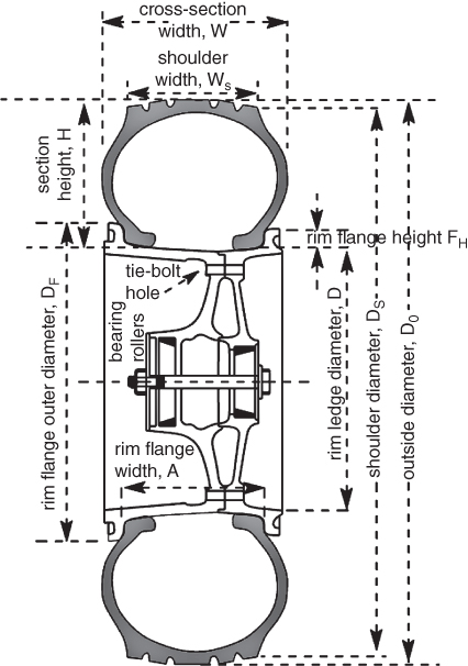
Figure F.1 Wheel and tyre nomenclature.
F.1. Glossary – Bias Tyres
- Apex strip. The apex strip is a wedge of rubber affixed to the top of the bead bundle.
- Bead heel. The bead heel is the outer bead edge that fits against the wheel flange.
- Bead toe. The bead toe is the inner bead edge closest to the tyre centreline.
- Breakers. Breakers are reinforcing plies of rubber‐coated fabric placed under the buff line cushion to help protect casing plies and to strengthen and stabilise the tread area. They are considered an integral part of the casing construction. The cords of breakers are not substantially aligned with the circumference of the tyre.
- Buff line cushion. The buff line cushion is made of rubber compounded to enhance the adhesion between the tread reinforcing ply and the top breaker or casing ply. This rubber layer is of sufficient thickness to allow for the removal of the old tread when the tyre is retreaded.
- Casing plies. Plies are layers of rubber‐coated fabric (running at alternate angles to one another), which provide the strength of the tyre.
- Chafer. A chafer is a protective layer of rubber and/or fabric located between the casing plies and wheel to minimise chafing.
- Chines. Also called deflectors, chines are circumferential protrusions that are moulded into the sidewall of some nose tyres that deflect water sideways to help reduce excess water ingestion into the engines. Tyres may have chines on one or both sides, depending on the number of nose tyres on the aircraft.
- Flippers. These layers of rubberized fabric help anchor the bead wires to the casing.
- Grooves. Circumferential recesses between the tread ribs.
- Liner. In tubeless tyres, this inner layer acts as a built‐in tube and helps to restrict gas from diffusing into the casing plies. For tube‐type tyres the liner helps prevent tube chafing against the inside ply.
- Ply turnups. Casing plies are anchored by wrapping them around the wire beads, thus forming the ply turnups.
- Sidewall. The sidewall is a protective layer of flexible, weather‐resistant rubber covering the outer casing ply, extending from tread edge to bead area.
- Tread. The tread is the outer layer of rubber which serves as the only interface between the tyre and the ground. It provides traction for directional control and braking.
- Tread reinforcing ply. Tread reinforcing plies are one or more layers of fabric that help strengthen and stabilise the tread area for high‐speed operation. It also serves as a reference for the buffing process in retreadable tyres.
- Tubes. A flexible hollow rubber ring that is inserted inside a pneumatic tyre to hold inflation pressure. Goodyear branded tubes meet SAE standard AS50141.
- Wire beads. The beads are hoops of high tensile strength steel wire that anchor the casing plies and provide a firm mounting surface on the wheel.
F.2. Glossary – Radial Bias Tyres
- Apex strip. The apex strip is a wedge of rubber affixed to the top of the bead bundle.
- Bead heel. The bead heel is the outer bead edge that fits against the wheel flange.
- Bead toe. The bead toe is the inner bead edge closest to the tyre centre line.
- Belt plies. Belts are a composite structure of rubber‐coated fabric that stiffen the tread area for increased landings. The belt plies increase the tyre strength in the tread area. The cords of belts are substantially aligned with the circumference of the tyre.
- Buff line cushion. The buff line cushion is made of rubber compounded to enhance the adhesion between the tread reinforcing ply and the overlay. This rubber layer is of sufficient thickness to allow for the removal of the old tread when the tyre is retreaded.
- Casing plies. Casing plies are layers of rubber‐coated fabric that run radially from bead to bead. The casing plies help provide the strength of the tyre.
- Chippers. The chippers are layers of rubber‐coated fabric applied at a diagonal angle that improve the durability of the tyre in the bead area.
- Chines. Also called deflectors, chines are circumferential protrusions that are moulded into the sidewall of some nose tyres that deflect water sideways to help reduce excess water ingestion into the engines. Tyres may have chines on one or both sides, depending on the number of nose tyres on the aircraft.
- Grooves. Circumferential recesses between the tread ribs.
- Liner. This inner layer of rubber acts as a built‐in tube and helps to restrict gas from diffusing into the casing plies.
- Overlay. The overlay is a layer of reinforcing rubber‐coated fabric placed on top of the belts to aid in high speed operation.
- Ply turnups. Casing plies are anchored by wrapping them around the wire beads, thus forming the ply turnups.
- Sidewall. The sidewall is a protective layer of flexible, weather‐resistant rubber covering the outer casing ply, extending from tread edge to bead area.
- Tread. The tread is the outer layer of rubber which serves as the only interface between the tyre and the ground. It provides traction for directional control and braking.
- Tread reinforcing ply. Tread reinforcing plies are one or more layers of rubber‐coated fabric that helps strengthen and stabilise the tread area for high‐speed operation. This also serves as a reference for the buffing process in retreadable tyres.
- Wire beads. The beads are hoops of high tensile strength steel wire that anchor the casing plies and provide a firm mounting surface on the wheel.
F.3. Tyre Terminology
- Ply rating. The term ‘ply rating’ is used to indicate an index to the load rating of the tyre. Years ago when tyres were made from cotton cords, ‘ply rating’ did indicate the actual number of plies in the carcass. With the development of higher‐strength fibres such as nylon, fewer plies are needed to give an equivalent strength. Therefore, the definition of the term ‘ply rating’ (actual number of cotton plies) has been replaced to mean an index of carcass strength or a load carrying capacity.
- Rated load. This is the maximum allowable load that the tyre can carry at the specified rated inflation pressure.
- Rated pressure. Rated pressure is the maximum inflation pressure to match the load rating. Aircraft tyre pressures are given for an unloaded tyre; that is, a tyre not on an aeroplane. When the rated load is applied to the tyre, the pressure increases by 4% as a result of a reduction in air volume.
- Outside diameter, D0. This measurement is taken at the circumferential centre line of an inflated tyre.
- Section width, W. This measurement is taken at the maximum cross sectional width of an inflated tyre.
- Rim diameter, D. This is the nominal diameter of the wheel/rim on which the tyre is mounted.
- Section height, H. This measurement can be calculated by using the following formula:

- Aspect ratio. Measure of the tyre's cross section shape. This can be calculated by the following formula: Aspect ratio = (Section Height)/(Section Width) = (H/W).
- Flange height, FH. This is the height of the wheel rim flange.
- Flange diameter, DF. The diameter of the wheel including the flange.
- Free height. This measurement can be calculated by using the following formula:

- Tyre shoulder: The shoulder of the tyre is where the treaded area meets the sidewall.
- Static loaded radius. This is the measurement from the centre of the axle to the runway for a loaded tyre.
- Loaded free height. This measurement can be calculated by using the following formula: Loaded Free Height = (Static Loaded Radius − Flange Diameter)/2.
- Tyre deflection. A common term used when talking about aircraft tyres is the amount of deflection it sees when rolling under load. The term % Deflection is a calculation made using the following formula: Percent Deflection = (Free Height − Loaded Free Height)/Free Height.
- Most aircraft tyres are designed to operate at 32% deflection, with some at 35%. As a comparison, cars and trucks operate in the 5–20% range.
- Service load (operational load). Load on the tyre at max aircraft takeoff weight.
- Service pressure (operational pressure). Corresponding pressure to provide proper deflection at service load.
- Rated speed. Maximum speed to which the tyre is qualified.
F.4. Typical Tyre Data
The full range of tyre data is freely downloadable from the Goodyear web site: www.goodyearaviation.com/resources/pdf/tire_specifications_7_2016.pdf.
Given next are the tyre data used in this book representing typical tyre types currently in use. These are Type III, Type VII and the new type three‐part name series also known as Type VIII, both bias and radial ply types in imperial unit and metric unit. From the Goodyear chart, only the pertinent parameters are taken, leaving out inflated tyre dimensions (used for stowage space considerations) and loaded tyre dimensions. Note: some older tyres were designated as either Type III or Type VII. The Type III tyres were mainly used by piston‐prop type aircraft with the attribute of low pressure for cushioning and flotation. Type VII tyres were early generation tyres designed for jet aircraft with higher load capacity.
Bizjet worked‐out example – Three‐part name series, tubeless type tyres:
In the example of a Bizjet tyre 22 × 6.6–10 (18‐ply), these have units in inches, 22 is the tyre diameter, 6.6 is the tyre width, the symbol ‘–’ indicates the tyre is of bias ply construction, 10 the rim diameter and has 18 ply (can follow the nomenclature with the designation 18PR).
Main wheel
| Size | Rating (ply) | Rated speed (mph) | Rated load (lbs) | Rated inflation (psi) | Max. braking load (lbs) |
| 22 × 6.6–10 | 18 | 230 (200 kt) | 10 700 | 260 | 16 050 |
| Wheel (Rim) size | Width between flanges (in,) | Specified rim diameter (in,) | Flange height (in,) | Minimum ledge width (in,) | |
| 22 × 6.6–10 | 5.5 | 10 | 1.0 | 2.05 |
Nose wheel
| Size | Rating (ply) | Rated speed (mph) | Rated load (lbs) | Rated inflation (psi) | Max. braking load (lbs) |
| 17.5 × 5.75–8 | 14 | 210 | 6050 | 220 | 9080 |
| Wheel (Rim) size | Width between flanges (in,) | Specified rim diameter (in,) | Flange height (in,) | Minimum ledge width (in,) | |
| 18 × 5.5 | 4.25 | 8 | 0.88 | 1.4 |
AJT worked‐out example – metric designation (rating in imperial units), tubeless type:
Main wheel
| Size | Rating (ply) | Rated speed (mph) | Rated load (lbs) | Rated inflation (psi) | Max. braking load (lb) |
| 450 × 190–5 | 22 | 233 | 8880 | 225 | 13 320 |
| Wheel (Rim) size | Width between flanges (in.) | Specified rim diameter (in.) | Flange height (inch) | Minimum ledge width (in.) | |
| 450 × 190–5 | 6.3 | 5 | 0.95 | 2.6 |
Nose wheel
| Size | Rating (ply) | Rated speed (mph) | Rated load (lbs) | Rated inflation (psi) | Max. braking load (lbs) |
| 450 × 190–5 | 10 | 230 | 3822 | 90 | 5730 |
| Wheel (Rim) size | Width between flanges (in.) | Specified rim diameter (in.) | Flange height (inch) | Minimum ledge width (in.) | |
| 450 × 190–5 | 6.3 | 5 | 0.71 | 1.38 |
TPT worked‐out example – Type III, tubeless type
Main wheel
| Size | Rating (ply) | Rated speed (mph) | Rated load (lbs) | Rated inflation (psi) | Max. braking load (lbs) |
| 6.50–10 | 8 | 160 | 4750 | 100 | 6890 |
| Wheel (Rim) size | Width between flanges (in.) | Specified rim diameter (in.) | Flange height (in.) | Minimum ledge width (in.) | |
| 6.50–10 | 4.75 | 10 | 0.81 | 1.10 |
Nose wheel
| Size | Rating (ply) | Rated speed (mph) | Rated load (lbs) | Rated inflation (psi) | Max. braking load (lbs) |
| 500–4.5 | 6 | 138 (120 kt) | 1650 | 78 | 2390 |
| Wheel (Rim) size | Width between flanges (in.) | Specified rim diameter (in.) | Flange height (in.) | Minimum ledge width (in.) | |
| 500–4.5 | 4 | 4.6 | 0.65 | 0.95 |
Airbus 320 class aircraft (main and nose dual undercarriage) – Three prt name series, tubeless type tyres:
Main wheel
| Size | Rating (ply) | Rated speed (mph) | Rated load (lbs) | Rated inflation (psi) | Max. braking load (lbs) |
| 49 × 19–20 | 32 | 235 | 51 900 | 219 | 77 800 |
| Wheel (Rim) size | Width between flanges (inch) | Specified rim diameter (inch) | Flange height (inch) | Minimum ledge width (inch) | |
| 46 × 16 | 13.25 | 20 | 1.88 | 3.75 |
Nose wheel (Radial tyre)
| Size | Rating (ply) | Rated speed (mph) | Rated load (lbs) | Rated inflation (psi) | Max. braking load (lbs) |
| 30 × 8.8R15 | 16 | 225 | 14 200 | 199 | 21 300 |
| Wheel (Rim) size | Width between flanges (in.) | Specified rim diameter (in.) | Flange height (in.) | Minimum ledge width (in.) | |
| 30 × 8.8 | 7.0 | 15 | 1.13 | 1.65 |
Small Recreation Aircraft below 3000 lb MTOW (not worked out in this book) – standard tube type tyres
Main wheel
| Size | Rating (ply) | Rated speed (mph) | Rated load (lbs) | Rated inflation (psi) | Max. braking load (lbs) |
| 600 × 6 | 4 | 120 | 1150 | 29 | 1670 |
| Wheel (Rim) size | Width between flanges (in.) | Specified rim diameter (in.) | Flange height (in.) | Minimum ledge width (in.) | |
| 600 × 6 | 5.0 | 6 | 0.75 | 0.8 |
Nose wheel
| Size | Rating (ply) | Rated speed (mph) | Rated load (lbs) | Rated inflation (psi) | Max. braking load (lbs) |
| 500 × 5 | 4 | 120 | 800 | 31 | 1160 |
| Wheel (Rim) size | Width between flanges (in.) | Specified rim diameter (in.) | Flange height (in.) | Minimum ledge width (in.) | |
| 500 × 5 | 3.50 | 5 | 0.75 | 0.8 |