6
Empennage and Other Planar Surfaces
6.1 Overview
Chapters 4 and 5 dealt with the pertinent aspects regarding the aerodynamic considerations of the wing and fuselage. The wing and body are found to be inherently unstable. Therefore, an empennage is required to balance this combined wing‐body instability as well as offer the requisite control to execute manoeuvres. This chapter is devoted, primarily, to describing the role of empennage, the physics involved, aerodynamic considerations, possible choices and the advantages and disadvantages of the options available. In this book, while the horizontal tail (H‐tail) and the vertical tail (V‐tail) are sized for new aircraft configuration, the control surfaces are not sized. Control surfaces are earmarked into their positions with statistically obtained typical sizes.
This chapter deals also discusses other types of lifting surfaces, for example, ailerons to execute roll control, LERXs (strakes) for additional vortex lift and other planar surfaces, as aircraft components, these are studied at the conceptual stage of a new aircraft design project. These planer surfaces have an aerofoil like cross‐section with chord length many times longer than the thickness. They are meant to generate forces and moments, some as modifiers to improve flow around bodies (e.g. dorsal fins, speed brakes serving as drag generators for deceleration) and others are mere support structures (e.g. a pylon).
This chapter covers the following topics:
- Section 6.2: Introduction
- Section 6.3: Terminologies and Definitions of the Empennage
- Section 6.4: Empennage Mount and Types
- Section 6.5: Different Kinds of Empennage Designs
- Section 6.6: Empennage Tail Arm
- Section 6.7: Empennage Aerodynamics
- Section 6.8: Aircraft Trim Tab and Control Surfaces types
- Section 6.9: Empennage Structural Considerations
- Section 6.10: Empennage Design
- Section 6.11: Other Planar Surfaces
Designing the empennage is not easy; it requires additional knowledge of aircraft stability and control; these subjects are offered in all academic institutes as separate courses requiring extensive treatment. The basics of aircraft stability and control required for aircraft design study are covered in Chapter 18. Preliminary configuration relies on the statistics of past designs, a practice widely used in the industry at the early stage of conceptual design study. Together with the wing and body, the empennage, engine and undercarriage present a complete new aircraft configuration. As mentioned earlier, this information serves to develop ‘boilerplate’ template geometries of aircraft components to be assembled to generate candidate aircraft configurations during the conceptual design phase (Chapter 8). Eventually, the chosen one will be formally sized as shown in Chapter 14.
Designers have to ensure that there is adequate trim authority available (trim should not run‐out) at any condition. This is normally done in Phase II after the configuration is frozen. In this book, the trim surfaces are earmarked and are not sized.
6.2 Introduction
In order to maintain steady flight, the aircraft requires empennage (or canard) surfaces to maintain stability. Section 3.8 introduced the idea that an aircraft has six degrees of motion in 3D space. The three angular motions in pitch, yaw and roll are controlled by the control surfaces as described in the following subsections.
6.2.1 The Role of the Empennage – Stabilising and Controlling
The role of the empennage is to offer stability to keep the aircraft flightworthy as well provide controllability to manoeuvre, as required in its mission role. The two angular motions, pitch and yaw, in the six degrees of freedom are controlled by two lift generating planer surfaces as an empennage mounted at the aft end of the fuselage in conventional designs at the aft of aircraft. These are achieved as follows (refer to Figure 3.11 for the body axes, FB, system). Figure 3.13 in Section 3.7.3 gives the sign convention associated with control deflection.
- Pitch stability and control (nose‐up/down in the x–z‐plane of symmetry – the pitch plane) by the lift generating planer surface as the H‐tail. Its fixed part (stabiliser) offers longitudinal stability and the movable part (elevator) provides the control (pitch moment, CM).
- Directional stability and control (yaw turns the x–z‐plane) by the symmetrical V‐tail. Its fixed part (fin) offers directional stability and its movable part (rudder) provides directional control (lateral moment, CN). Having no constraints, the centrifugal force developed in a pure turn in a level wing will be associated with slide slip. It has to be a coupled motion with some degree of roll (bank) using wing mounted ailerons to accomplish a no sideslip coordinated turn.
6.2.2 The Role of Ailerons – Stabilising and Controlling
The third angle of motion is rolling. Lateral roll control in the y–z‐plane can be performed with ailerons at the wing tips' trailing edges. The opposite deflection of ailerons at each side gives the rolling moment, CL (not to be confused with the lift coefficient, CL). Ailerons conform to the aerofoil profile of the wing and are not part of the empennage. Roll has coupled motion with yaw.
Like wings, empennage planform shapes are also basically of two types: (a) unswept and (b) swept. H‐tails can also have dihedral/anhedral angles for the same reason as they are applied to the wing configuration (see Section 4.4.1). The empennage configuration follows similar considerations as wing design to establish the aspect ratio (AR), sweep, taper ratio, dihedral angle and twist. There are basically three types of empennage configurations as shown in Figure 6.1.
- The most common method, as the conventional practice, is to install a horizontal planar surface (termed as H‐tail) at the far aft end for pitch stability and control of the aircraft (Figure 6.1a). Lateral stability and control is achieved via a vertical planar surface (termed the V‐tail) at the far aft end in the plane of symmetry. Since it is at the end, it is seen as the tail of an aircraft as a part of the empennage.
- Described in Section 1.2, the Wright brothers' ‘Flyer’ configuration had a canard configuration (tail in front). This kind of design has steadily gained ground in the last three decades, especially in combat aircraft design (Figure 6.1b).
- For a single surface delta wing aircraft (Mirage 5) and all‐wing configuration (B2), part of the tail offering a nose‐up moment is merged with the wing as its reflex movable trailing edge (Figure 6.1c). The differential movements of these trailing edges also act as ailerons, known as elevons (see Section 6.5). Depending on the technology adopted, blended‐wing‐body (BWB) aircraft may or may not have a V‐tail.
Except for very small number of designs, all aircraft are symmetrical to their vertical plane, that is, from its centreline, the port side and starboard side are the mirror images of each other. Therefore, the aircraft is without any lateral moments in straight flight along its plane of symmetry. It becomes essential to provide a vertical surface (V‐tail) that can be manipulated to generated lateral moment (CN) to the extent required to execute a yaw turn. This is known as the V‐tail part of the empennage. It has a symmetric aerofoil.

Figure 6.1 Typical empennage designs. (a) Conventional, (b) canard configuration and (c) H‐tail merged with the wing (tailless).
Although two examples of DATCOM methods are given in this chapter to understand the physics of the problem, this book relies on the statistics of past designs as given in Chapter 7.
6.3 Terminologies and Definitions of Empennage
Empennage shaping observes the rules of wing design with wings being lifting surfaces. Modern aircraft with Fly‐by‐Wire (FBW) technology can operate with more relaxed stability margins, especially for military designs, and hence require smaller empennage areas compared with older conventional designs (see Figure 18.18). The terminologies associated with the empennage are given in the following subsections (Figure 6.2).
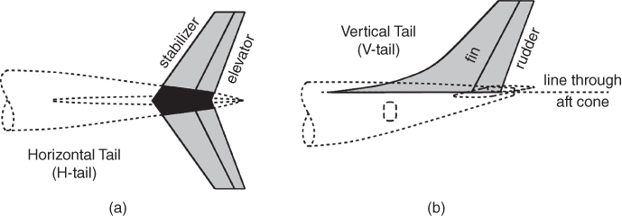
Figure 6.2 (a) Horizontal tail and (b) vertical tail.
6.3.1 Horizontal Tail (H‐Tail)
A H‐tail is like a small wing at the tail (i.e. the aft end of the fuselage). It consists of the fixed or moving stabiliser and the moving elevator for controlling the pitch degree of freedom (Figure 6.2a). In general, the H‐tail has a negative camber to give a nose‐up moment to counterbalance the inherent nose‐down moment of a tailless wing‐fuselage combination (see Section 6.7.4). The H‐tail can be positioned low at the fuselage side, in the middle cutting through the V‐tail or at the top of the V‐tail to form a T‐tail (see Figure 6.3). Like the wing planform definition, the H‐tail reference area, SHT. For a low tail, part of SHT, is buried inside the fuselage. The T‐tail at the top of the V‐tail has a fully exposed planform. The mid‐tail has a small part of SHT buried within the V‐tail.
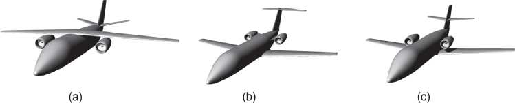
Figure 6.3 The dominant options for the wing, tail and nacelle positions. (a) Low tail, under‐wing pods, (b) high T‐tail, fuselage‐mounted pods and (c) mid‐tail (cruciform), over wing pods.
Typically, for civil aircraft, H‐tail planform area is anywhere from one‐third to a quarter of the wing planform size, AR ≈ 3.0, sweep is about same as the wing and there is no twist, but it can have dihedral/anhedral angles. The T‐tail on a swept back V‐tail permits a longer tail arm, LHT (Section 6.8).
Military aircraft empennage sizing requires special attention as they require more control authority for greater manoeuvrability. Modern combat aircraft have lower wing AR values and have shorter tail arms requiring larger H‐tail areas.
6.3.2 Vertical Tail (V‐Tail)
The V‐tails have a symmetrical aerofoil section unbiased to either side to turn. The V‐tail consists of a fixed fin and a moving rudder to control primarily the yaw degrees of freedom but has coupled motion with roll. The V‐tail is positioned at the plane of aircraft symmetry and has a symmetrical aerofoil. The V‐tail of a fuselage‐mounted propeller driven aircraft may be given skew (small amount of incidence angle) to counter yaw developed by its swirling slipstream.
Figure 6.2b shows the geometrical definition of a conventional V‐tail surface reference area, SVT. Depending on the closure angle of the aft fuselage, the root end of the V‐tail is fixed arbitrarily through a line drawn parallel to the fuselage reference line, passing through tail cone, hence it can be partly buried into the fuselage. The projected area up to its root end is considered the reference area, SVT of the V‐tail. Other definitions takes the V‐tail root at the fuselage reference line, which may not pass through the tail cone.
Typically, for civil aircraft, the V‐tail planform area is about 12–20% of wing reference area. V‐tail design is critical to takeoff (to satisfy Vmc – see Chapter 15) – especially to tackle yawed ground speed arising from cross‐winds and/or asymmetric power of multi‐engine aircraft. A large V‐tail can cause snaking of the flight path at low speed, which can be easily cured by introducing a ‘yaw‐damper’. At cruise, a relatively large V‐tail is not a problem but ensures safer operation. V‐tail is half span, its AR is based on full span.
6.4 Empennage Mount and Types
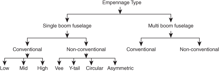
Chart 6.1 tabulates the variety of empennage configuration options available in a systematic way. Note that other kinds of empennage configurations are possible (canard design not included).
6.4.1 Empennage Positional Configuration – Single Boom
6.4.1.1 Conventional type
By far, the majority of civil aircraft designs have two surfaces almost orthogonal to each other as the H‐tail and V‐tail. The H‐tail can be positioned low at the fuselage (Figure 6.3a – has a dihedral angle) or at the top as a T‐tail (Figure 6.3b – has an anhedral angle) or anywhere in between (Figure 6.3c) as a mid‐tail (also known as a cruciform tail) configuration. Any combination of the scheme is feasible but it is decided on from the various aerodynamic, stability and control considerations. The V‐tail is kept symmetric to the aircraft centreline and can be swept (there are exceptions). Twin V‐tails (military aircraft) can be straight or inclined. The advantages and the disadvantages of the three setups are given next.
- Low tail
This is the well‐proven configuration, adopted by the majority of aircraft designs, used especially in large commercial aircraft applications.
Advantages
- Robust structural integrity for being attached to the girth of an aft fuselage offering best resistance to torsion under empennage load.
- Wing downwash on the H‐tail can be well utilised, especially in a wing flap extended position.
- Careful positioning of the H‐tail can avoid wing wake interfering with the H‐tail as shown in Figure 6.16 later.
Disadvantages
- Can shield the V‐tail in spin (see Figure 6.15).
- High interference drag – both at the upper and lower surfaces of the H‐tail joint.
Examples: All Airbus and Boeing commercial transport aircraft currently in production.
6.4.1.2 High tee‐tail (t‐tail)
The other extreme of H‐tail position is placed at the top of the V‐tail suiting an aircraft with aft fuselage‐mounted engines to stay away from the engine exhaust.
Advantages
- On account of V‐tails being made swept back, the H‐tail arm is longer for the same size fuselage. Longer tail arms reduce H‐tail size for the same tail volume coefficients (Section 6.10).
- Does not shield the V‐tail (see Figure 6.15).
- Low interference drag – only at the lower surfaces of the H‐tail joint.
Disadvantages
- The V‐tail becomes too heavy to support a T‐tail and provide torsion rigidity.
- In deep stall, wing wake may affect the T‐tail elevator authority that may cause aircraft to enter into flat spin when recovery may become difficult. For example, the BAe 111 flight test crash in October 1963 and similar crashes that occurred with many other aircraft. The stabilator (see Section 6.5.3) type of T‐tail may become a necessity.
- Prone to flutter.
Examples: Learjet series, Boeing727, Beech King aircraft, C17 military transport aircraft and so on.
6.4.1.3 Mid‐tail (cruciform tail)
This configuration is in between the two extremes as described here, meant for aft‐mounted engines. This is a good compromise by raising the H‐tail just above engine exhaust interference.
Advantages
- May have a neutral rolling moment.
- Lower structural weight as compared to the T‐tail of the same size.
- Partial rudder available for spin recovery.
Disadvantage
- High interference drag – both at the upper and lower surfaces of the H‐tail joint.
- Does not have a tail arm as long as the T‐tail can get for the same fuselage length.
Examples: Sud Aviation Caravelle, Jet Stream, Dassault Falcon and so on.
6.4.1.4 Unconventional Empennage types
Figure 6.4 shows the dominant unconventional empennage design options (this figure can also be used to illustrate the wing and nacelle position options). The merits of the unconventional empennage have its applicability but by far the majority of designs have one horizontal and one vertical surfaces. This book deals only with the conventional designs.
- Vee‐tail/Y‐tail (Figure 6.4)

Figure 6.4 Other types of civil aircraft empennage design option. (All figures except the LearFan and Marvel aircraft). (a) Vee‐tail Beech Bonanza. (b) Y‐tail (Lear Fan). (c) Circular tail (Courtesy: www.aviastar.org/ Courtesy: Mississippi air/usa/learavia_learfan.php State University [email protected] Marvel. (d) Twin V‐tail on twin boom: De Havilland Sea Vixen. (e) Twin V‐tail on H‐tail: Short Sky van. (f) Three V‐tail (Lockheed Constellation).
Source: Reproduced with permission of Ferrier.
The Beechcraft Bonanza 35 has a vee‐shaped tail (not be confused with a V‐tail) and in some designs it can be an inverted vee‐tail (ruddervator – see Section 6.5.1). One of the early Lear designs had Y‐shaped empennage – a vee‐tail along with a vertical fin extending below the fuselage. Vee‐tail/Y‐tail designs are more complex but follow the same routine as the conventional ones, that is, resolving the forces on the surfaces into vertical and horizontal directions. The MacDonnell Douglas F4 Phantom H‐tail has a high degree of anhedral angle, almost like an inverted vee‐tail, like a wide open inverted Y‐tail. A proper Y‐tail configuration can be seen in the LearFan 2100 manufactured at their Belfast based factory.
- Twin tail/triple tail (Figure 6.4)
If the V‐tail size is large on account of a short tail arm, then the area could to be split into two (Short Skyvan) or three V‐tails (Lockheed Constellation) arising from structural and aerodynamic considerations. Multiple V‐tails are placed symmetrically about the aircraft plane of symmetry. The short 330 aircraft is a good example of a twin‐tail configuration with rear loading facility. The end plate effect of a V‐tail on H‐tail increases its effectivity as well as decreases H‐tail induced drag.
- Circular empennage (Figure 6.4)
An experimental aircraft with a circular tail was designed by the Mississippi State University in the 1960s as a research platform. It does not appear to have shown definite advantages over conventional empennage design to supplant it.
6.4.2 Empennage Positional Configuration – Multi‐ (Twin) Boom
6.4.2.1 Conventional Empennage types
- Fuselage mounted
Many successful aircraft and Unmanned Aerial Vehicles (UAVs) have been designed with a twin boom accommodating an empennage; for example, the Lockheed P38, North American F‐82 Twin Mustang, De Havilland Fairchild C119, Vampire/Sea Vixen, Cessna Skymaster and so on all have a V‐tail each on the fuselage twin booms and the H‐tail joining them (or an inverted vee‐tail). It suits rear mounted pusher aircraft designs, centrally placed jet engines and, in the case of the P38, the booms extends from piston engine nacelles. The propeller slipstream from each of the boom mounts assists the empennage effectivity.
6.5 Different Kinds of Empennage Design
Apart from the conventional type of empennage, there are other kinds described in the next subsections.
6.5.1 Ruddervator
The ruddervator is a novel concept first suggested in the early 1930s by combining the actions of H‐tail and V‐tail into a ‘vee’‐shaped tail, which can be seen as a dihedral of an H‐tail to about half way at Γ ≈ 45° and eliminating the V‐tail. Its inverted shape is also possible with Γ ≈ −45°.
The lift forces normal to the inclined ruddervator are resolved along the pitch plane and yaw plane. When the pilot control stick is pulled or pushed, then the movable part at both sides of the ruddervator move together up or down to give nose‐up or nose‐down, respectively; here yaw‐plane force components cancel each other. For turning, the rudder pedals are used when differential movement at each side occurs. This time, the force components in the yaw plane are in the same direction as shown in the last diagram of Figure 6.5 for a left turn. However, force components in pitch are equal and opposite but produce a couple of forces to give some rolling moment to the left, assisting a coordinated turn with bank angle.
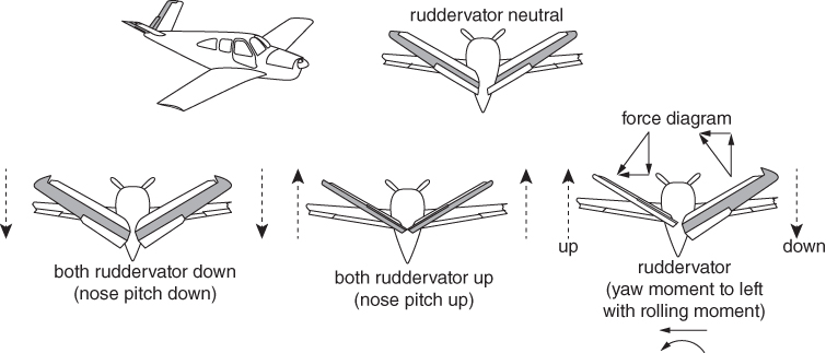
Figure 6.5 Ruddervator (Vee‐tail).
While there are successful models are in operation, for example, the Beechcraft Bonanza 35 (small propeller driven utility aircraft), Fouga Magister C170 and variants (military jet trainer of French origin), and few others.
A properly sized vee‐tail design has some advantages as follows:
- Control surfaces are not shielded and control authority is available in spin.
- No‐slip coordinated turn is possible without or needing little application of ailerons.
- There is sufficient ground clearance if the aircraft tips at one side and so on.
However, there are some unfavourable issues as follows:
- It requires a complex control mechanism and is relatively heavy.
- It needs a larger area, which also makes it heavy.
- It has coupled control and controlling aircraft in gusty weather during takeoff and landing can prove to be more difficult compared to using a conventional empennage with an H‐tail, V‐tail and so on.
An inverted vee‐tail is a possibility offering similar design considerations. This is a rare application and only came as proposition (Blohm Voss VM 213) i some microlites (with a twin boom joined by an inverted vee‐tail), but is used noticeably in UAV designs. Studying the UAV configurations, it is clear that the aft‐mounted propeller pusher UAV design configurations have long undercarriages for ground clearances allowing an inverted vee‐tail (see the Ikhana in Figure 1.17a).
It is for these reasons that the vee‐tail/Y‐tail and their inverted version concepts did not catch on. Practising engineers may refer to NACA‐ACR‐L5A03 [1] (also known as NACA TR‐823) for detailed study.
6.5.2 Elevon
Elevons are aircraft control surfaces that combine the functions of the elevator (used for pitch control) and the aileron (used for roll control), hence the name: a portmanteau (blended word) of elevator and aileron. (Figure 6.1b). They are frequently used on tailless aircraft such as flying wings.
Elevons are installed on each side of the aircraft at the trailing edge of the wing. When moved in the same direction (up or down) they will cause a pitching force (nose‐up or nose‐down) to be applied to the airframe. When moved differentially (one up, one down), they will cause a rolling force to be applied. These forces may be applied simultaneously by appropriate positioning of the elevons, for example, one wing's elevon completely down and the other wing's partly down.
An aircraft with an elevon is controlled as though the pilot still has separate aileron and elevator surfaces at his disposal, controlled by the yoke or stick. The inputs of the two controls are mixed either mechanically or electronically to provide the appropriate position for each elevon. Delta wings with reflex trailing edges have elevons, for example, on the F‐102A Delta Dagger, Mirage 5 and so on.
6.5.3 Stabilator/Taileron
A stabilator (a blended word of ‘stabiliser‐elevator’), also known as a taileron, is a fully movable aircraft stabiliser. It has several other terminologies, for example (i) all‐moving tailplane, (ii) all‐movable tail (plane), (iii) all‐moving stabiliser, (iv) all flying tail (plane), (v) full‐flying stabiliser, (vi) flying tail, (vii) slab tailplane and (viii) taileron. It serves the usual functions of longitudinal stability, control and stick force requirements otherwise performed by the separate fixed and movable parts of a conventional horizontal stabiliser. Apart from a higher efficiency at a high Mach number, it is a useful device for changing the aircraft balance within wide limits and for mastering the stick forces. Stabilators may not prove best suited to subsonic aircraft design.
Military aircraft can have all‐moving H‐tails with emergency splitting to act as elevators in case there is failure of the stabilator and there are several choices for positioning it for splitting, typically at 40% of the mean aerodynamic chord (MAC).
6.5.4 Canard Aircraft
Canard is French for duck, which in flight stretches out its long neck with its bulbous head in front. When a horizontal surface is placed in front of the aircraft, it presents a similar configuration; hence, this surface is sometimes called a canard. A canard is an aerodynamic arrangement wherein a small forewing or foreplane is placed forward of the main wing of a fixed‐wing aircraft. The term ‘canard’ may be used to describe the aircraft itself, the wing configuration or the foreplane (see Section 6.6.1).
Despite the use of a canard surface on the first powered aeroplane, the Wright Flyer of 1903, canard designs were not built in quantity until the appearance of the Saab Viggen jet fighter in 1967. The aerodynamics of the canard configuration are complex and require careful analysis.
Rather than use the conventional tailplane configuration found on most aircraft, an aircraft designer may adopt the canard configuration to reduce the main wing loading, to better control the main wing airflow, or to increase the aircraft's manoeuvrability, especially at high angles of attack or during a stall. Canard foreplanes, whether used in a canard or three‐surface configuration, have important consequences on the aircraft's longitudinal equilibrium, static and dynamic stability characteristics. A military canard is meant for high manoeuvrability and a civil canard is meant for static stability and weight reduction.
6.6 Empennage Tail Arm
The destabilising moments from wing, fuselage and nacelle are balanced by the empennage moments about the aircraft centre of gravity (CG) [2]. The tail arms are the length of the moment arms of the lift forces developed by the H‐tail and V‐tail. The respective tail arms are denoted lHT for the H‐tail and lVT for the V‐tail both acting at the respective aerodynamic centre close enough to ¼MAC. These are important parameters for sizing the empennage for aircraft stability and control, measured from the CG; its position changes according to the payload and fuel load distribution change.
Therefore, it is convenient if fixed moment arms can be considered if they are close to the moment arm measured from the CG (Figure 6.6). To generate statistics from past designs, a fixed position between wing and empennage proves convenient. In this case, for conventional two‐surface aircraft configuration, a tail arm is defined as the length between the quarter point of wing (MAC)¼_wing and quarter point of tail (MAC)¼_H_tail denoted l′HT and (MAC)¼_V_tail denoted l′VT. Typically, CG variation in civil aircraft is less than 10–15% of the MAC and for military aircraft around 5–10% of the MAC keeping its quarter‐chord point within the margin of movement. Typically, conventional aircraft have their CG close to (MAC)¼_wing, making lHT ≈ l′HT and lVT ≈ l′VT, removing ambiguity as they are treated as the same.

Figure 6.6 Geometric parameters for the tail volume coefficient.
The terms lHT and lVT are important parameters to size empennage areas obtained from the non‐dimensional tail volume coefficients defined in Section 6.6.2. Strictly speaking, statistics of tail volume coefficients from both CG and MAC¼ should be separately considered. However, the differences between them are very small, contained well within the bands of statistical dispersion. Therefore, from now onwards, only the terms lHT and lVT are used to denote the respective tail arms. Whichever method is used, the final result will be the same so long as appropriate interpretation is followed in the computational process.
At the conceptual design stages, when the aircraft wing position relative to the empennage is yet to be settled, it is more appropriate to initially guess a CG position to compute tail arms and subsequently fine‐tune the tail arm lengths as the CG changes. It is for this reason in this book the tail arms are measured from the aircraft CG.
6.6.1 Canard Configuration
The Wright Brothers' Flyer had a control surface at the front (with a destabilising effect), which resulted in a sensitive control surface. The last two decades have seen the return of aerodynamic surfaces placed in front of the wing. Figure 6.7a shows a three‐surface canard Piaggio P180 Avanti and Figure 6.7b shows a two‐surface canard Rutan Long‐EZ aircraft. The canard surface can share some lift (in civil aircraft designs) with the wing.
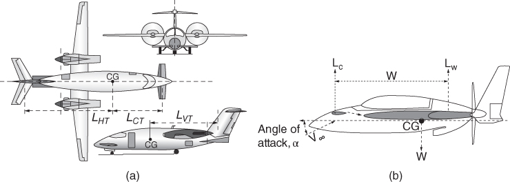
Figure 6.7 Canard configurations. (a) Three‐surface canard (Piaggio P180 Avanti) and (b) two‐surface canard.
In general, the inherent nose‐down moment (unless a reflex trailing edge is employed) of a wing requires a downward force by the H‐tail to maintain level flight. This is known as trimming force, which contributes to trim drag. For an extreme CG location (which can happen as fuel is consumed), high trim drag can exist in a large portion of the cruise sector. The incorporation of a canard surface can reduce trim drag as well as the H‐tail area, SHT; if not, eliminate the aft H‐tail as in the case of the Long‐EZ. Until recently, the benefit from the canard application in large transport aircraft has not been marketable.
A successful Bizjet design is the Piaggio P180 Avanti has achieved a very high speed for its class of aircraft through careful design considerations embracing not only superior aerodynamics but also the use of composite materials to reduce weight. Military aircraft use a canard to enhance pitch control. Canards in military aircraft have a special role to execute extreme manoeuvres.
6.6.2 Tail Volume Coefficients
The CG position is shown in Figure 6.6. The distances from the CG to the quarter‐chord of the V‐tail and H‐tail MAC (i.e. MACVT/4 and MACHT/4) are designated lHT and lVT, respectively. The aircraft a.c. is taken at the quarter‐chord of the wing MACW/4.
The tail volume coefficients are non‐dimensional parameters: this lumps together all the influencing variables that arise in stability analyses (Eqs. 6.1 and 6.2). Figure 7.8 gives statistical values of tail volume coefficients and tail areas with respect to wing area.
6.6.2.1 H‐tail volume coefficient, CHT
Define H‐tail volume coefficient is derived in terms of the H‐tail plane reference area, SHT, as follows.
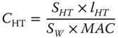
or

where CHT is the H‐tail volume coefficient, 0.5 < CHT < 1.2; a good value is between 0.6 and 0.9. lHT is the H‐tail arm = distance between the aircraft CG to the MACHT/4. In general, the area ratio SHT/SW ≈ 0.20–0.35. H‐tail span is about a third of the wing span. Figure 7.8 gives a cluster of V‐tail designs with tail volume coefficients A good starting point is to take CVT ≈ 0.07, AR ≈ 1.0–1.75, sweep is about same as the wing and no twist.
6.6.2.2 V‐tail volume coefficient, CVT
Define V‐tail volume coefficient is derived in terms of the H‐tail plane reference area, SVT, as follows.
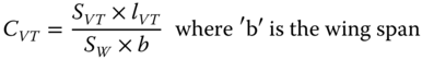
or

where CVT is the V‐tail volume coefficient, 0.05 < CVT < 0.1; a good value is between 0.06 and 0.09. lVT is the H‐tail arm = distance between the aircraft CG to the a.c. of MACVT. In general, the area ratio SVT/SW ≈ 0.15–0.26.
Equations 6.1 and 6.2 give a good indication of what kind of empennage size is to be expected. Having the tail arm and wing area established from the configuration obtained in the preliminary study (Chapter 8 gives the worked‐out examples), the empennage sizes depend on the values of CHT and CVT chosen for the design from the existing statistics for the H‐ and V‐tail, respectively. It is recommended to take higher values of CHT and CVT to have a generous sized empennage to ensure safety with better control authority. The weight penalty is small; if required, the empennage can be fine‐tuned after prototype flight testing by tailoring to smaller than the initial sizes.
Figure 7.8 gives a cluster of V‐tail designs with tail volume coefficients A good starting point is to take CVT ≈ 0.07, AR ≈ 1.0–1.75, sweep about same as the wing and no twist. The T‐tail acts as an end plate at the tip of V‐tail when, for the T‐tail configuration, tail volume, CVT, could be reduced. Like wing design, the V‐tail can have sweep, but dihedral/anhedral and twist is meaningless, as the V‐tail needs to be symmetric about the fuselage centreline. For propeller driven aircraft, the V‐tail could be kept slightly skewed (≈ 1°) to offset swirled slipstream effects and gyroscopic torque of rotating engines and propellers. Sweeping of the V‐tail would effectively increase the tail LVT, an important dimension to sizing the V‐tail. It is important to ensure that the V‐tail, especially the rudder, is not shielded by the H‐tail to retain effectiveness, especially during spin recovery. With a T‐tail, there is no shielding.
Military aircraft empennage sizing requires special attention as these require more control authority for greater manoeuvrability. Modern combat aircraft with FBW system architecture have a lower wing AR and shorter tail arms, requiring relatively larger tail areas. With FBW system architecture, this reduces the V‐tail size with CVT ≈ 0.07–0.09, AR ≈ 3.0, sweep is about the same as the wing. The V‐tail area varies from 15 to 25% of the wing reference area. Fighter aircraft have an all‐movable tail for control. If the V‐tail is too large then it is split into two.
6.6.2.3 Canard volume coefficient, CCT
This also is derived from the pitching‐moment equation for steady‐state (i.e. equilibrium) level flight. The canard reference area, SC, has the same logic for its definition as that of the H‐tail. Its tail arm is lCT. The canard reference area is given as:

or

where CCT is the H‐tail volume coefficient, 0.5 < CHT < 1.2; a good value is 0.6–0.9, depending on whether it is a conventional H‐tail. The lCT is the H‐tail arm = distance between the aircraft CG to the ac of MACCT. In general, SCT/SW ≈ 0.2–0.6.
6.7 Empennage Aerodynamics
Empennage design involves detailed stability and control analyses, which are beyond the scope of this book. Aircraft static stability is dealt with in a generalised manner in Chapter 18. However, to understand empennage design, the pertinent topics on aircraft stability and the associated aerodynamics are briefly described in this section. Only conventional empennages are dealt with here, both having fixed and a movable surfaces. The H‐tail is discussed first. Readers may refer to References [2–9] dedicated to aircraft stability and control for further reading.
6.7.1 Wing Downwash on the H‐tail
Section 4.9.1 (Figure 4.16) dealt with wing downwash, ε, which flows over the H‐tail (typically with an inverted aerofoil) at an angle of incidence, αht, with respect to the stabiliser as shown in Figure 6.8. (It is convenient to express all the relevant angles associated with downwash measured with respect to a fixed fuselage reference line established by the designer; typically, from aircraft nose to tail tips.)
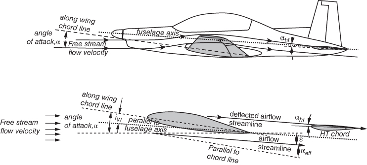
Figure 6.8 H‐tail aerodynamics.
From Figure 6.8, the following angles are observed.
- α = angle of attack, the angle between free stream velocity, V, and the wing chord line. Depending on the aircraft attitude, α, can vary.
- iw = Wing and fuselage setting angle. This is the fixed geometric angle measured between MAC and fuselage reference line. Being invariant, it offers convenience to measure all other angles that can vary. The angle is meant to offer minimum drag at long range cruise (LRC) speed. Typically, iw ≈ 2 ± 1°.
- αht = This is at angle of attack at the H‐tail, the angle between wing downwash deflection velocity of 2w with the H‐tail MACHT. The angle of attack, αht, can vary, depending on aircraft velocity and pitch attitude. αht has to be computed.
- it = This is angle between the H‐tail MACHT and fuselage reference line. It can be either fixed or can be rigged to a different setting angle on the ground, or can be set by the pilot in flight.
- εd = This is the downwash deflected angle and is twice the downwash angle, ε, at the aerodynamic centre, a.c., of the wing MAC.
From this information,
The intention is to develop the CL_HT required to produce downward force to balance the destabilised nose‐down moment of the tailless aircraft.
For small aircraft, the stabiliser part of the H‐tail is fixed to fuselage after satisfactory completion of flight testing prototype aircraft before the final version is produced. Some smaller utility type aircraft can get H‐tail rigged on ground before a sortie to suit the loading condition. However, for larger aircraft, to expand the elevator control authority, the stabiliser can be adjusted in flight by the pilot. To achieve fast response to control, combat aircraft have an all‐moving H‐tail as shown in Figure 6.19, later.
6.7.2 H‐tail – Longitudinal Static Stability: Stick‐Fixed and Power‐Off
Aircraft pitch stability analyses is in its pitch plane with rotation about the y‐axis. The H‐tail, with a fixed stabiliser and a movable elevator, requires the stabiliser part to provide adequate pitch stability. In normal operation, the control stick is held by the pilot, keeping the elevator in a fixed position is known as the stick‐fixed case. When the elevator fails (or the pilot leaves the control stick free) that will make the elevator to flap freely about its hinge line contributing nothing, rendering it useless. This situation of the elevator moving freely is termed the stick‐free case, a design consideration to ensure safety in this undesirable situation. To relieve pilot fatigue by continuously applying force to hold the stick in place, trimming devices (see Section 6.8) are installed, when the pilot can ease off but should not control stick‐free. This section deals only with the stick‐fixed and power‐off case. The most critical situation for H‐tail design is at the permissible aft‐most aircraft CG when aircraft stability and control authority are in high demand.
Figure 6.9 gives the geometric and kinetic information about a conventional aircraft to explain the physics behind aircraft longitudinal static stability. In this simplification, it is considered that the vertical height of aircraft CG is very close to the fuselage reference line, thus making the wing and nacelle close enough to make small contributions to moments in comparison with other contributions, hence they are neglected. (The rigorous method follows the same procedure without ignoring any contribution to pitching moment generation.)
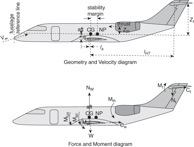
Figure 6.9 Aircraft forces and moments (power‐off).
In summary, the vertical distances (z) of each component could be above or below the CG, depending on configuration as described next.
- Drag of low wing below CG (za) will have a nose‐down moment and vice‐versa for high wing. For mid‐wing positions, it has to be noted on which side of CG it lies and could have a za small enough to be ignored for a preliminary analysis.
- The H‐tail area is considerably smaller than the wing, so is its drag that can be neglected even when positioned as a T‐tail at this stage of study.
- Under‐wing slung engines have a zth below the CG generating a nose‐up moment. For fuselage‐mounted engines, zth is likely to be above the aircraft CG and its thrust would generate a nose‐down moment offering stability. For most military aircraft, the thrust line is very close to the CG and hence for a preliminary analysis, the zth term can be ignored; that is, no moment generated with thrust (unless vectored). Since, the section considers a power‐off situation as the critical case, moment contribution by thrust is not considered. Nacelle height, being closer to CG, means its drag is also not taken into account under this simplification.
In equilibrium flight, the role of the H‐tail is to provide a sufficient opposite moment to balance the moments developed by the rest of the aircraft for the full flight envelope, as equated next.
The governing generalised equation for aircraft stability in coefficient form, derived in Equation (18.8), is shown in Eq. 6.5. In equilibrium, CM_cg = 0, that makes,
where, ηt (= qt/q∞) represent the wing wake effect on the H‐tail, producing downwash, qt is the incident dynamic head and q∞ is the free stream dynamic head. The value of ηt varies from 0.95–1.0. Note that for conventional aircraft with aft‐most CG, the CLHT requires downward force to keep nose‐up, hence it carries the opposite sign. The worked‐out example, Example 6.1, assigns the appropriate signs.
By transposing, Eq. 6.5 can written as follows.
Given next is the simplified version to establish the methodology to size the H‐tail. Further simplification can be made by studying the order of magnitude of the moment contributed by each term. Typically, an H‐tail has a low negative camber, if not without camber, in the case of small recreational types of aircraft, one can get away with a flat plate. The CM_t of the H‐tail stays low as well the ratio of (SHT)/(Sw) is in the order of 0.25–0.3: on the other hand, the long tail arm, lt, is the main contributor to the nose‐up moment. In other words, [CM_ht × (SHT/Sw) × ηt] < <[CLt × (SHT/Sw)(lHT/c) × ηt], hence it can be neglected, yet a realistic sized H‐tail area, SHT, can be obtained.
Equation 6.6 can now be written as
Using Eq. 6.1,
where ![]() (for a T‐tail above the wing wake, ηt = 1.0 and here c = wing MAC).
(for a T‐tail above the wing wake, ηt = 1.0 and here c = wing MAC).
Equation 6.6 reduces to a simple usable expression for easy computation as:
For a given wing, Figure 6.10 gives the limits of H‐tail size. H‐tail growth moves the neutral point (NP) aft and the CG can be allowed to move aft retaining the safe static margin for stability. H‐tail growth also permits the CG limit to move forward as more elevator power is available at the cost of increased stick force. The H‐tail size is at the allowable stick force limit at the forward‐most CG position that gives the sized CG travel within the acceptable limit. The shaded area shown in the figure gives a choice to for H‐tail size within the prescribed CG travel limits and the stick force limit.
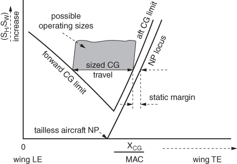
Figure 6.10 H‐tail sizing.
Stability requires the CG to be ahead of NP offering a sufficient stability margin, defined as follows.
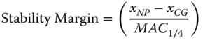
expressed as a percentage of wing MAC.
6.7.3 V‐tail – Directional Static Stability: Rudder‐Fixed
Aircraft directional stability analyses follows the same routine as of the longitudinal stability analyses, this time about z‐axis rotation in the yaw plane instead of about y‐axis rotation in the pitch plane. The aircraft, being symmetrical about the vertical (pitch) plane, has directional stability that behaves like a weathercock. Therefore, in principle, aircraft flying straight along the plane of symmetry do not produce a yaw moment. In reality, even when aircraft flystraight in along the plane of symmetry there will be yawing moments on account of (i) spiralling propeller slipstream flow, (ii) asymmetric power setting for multi‐engine aircraft, (iii) any cross‐wind gusts and so on. Unlike aircraft pitching stability, the physics of directional stability can be complex as the direction (yaw) and lateral (roll) motions are cross‐coupled. V‐tail rudder actuation offers both yaw and roll moments. While an aircraft is meant to rotate about the z‐axis to get yaw, it also develops significant roll about the x‐axis. Ailerons, not part of the empennage, also have cross‐coupled motions. Activation of roll about the x‐axis with aileron deflections is also coupled with yaw. Uncoupled yaw without roll will make an aircraft side slip (Figure 6.11).
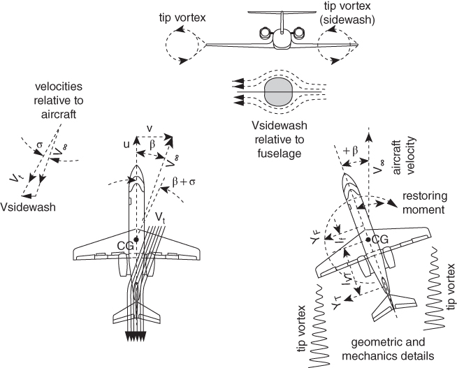
Figure 6.11 Direction stability (also see Section 18.3.2 for more explanation).
To encounter yaw moment, aircraft in yaw attitude must have static directional stability to return to its equilibrium state. Also, an aircraft requires deliberate yaw moment by rudder deflection to turn in a yaw plane (it is not a coupled coordinated turn but associates with side slip). In this book, only the rudder‐fixed directional stability is discussed. It is analogous to the stick‐fixed case in the study of pitch stability.
Figure 6.11 gives the geometric and kinematic details considered in analyses. The aircraft is shown flying at a velocity V∞ at a positive side slip to starboard side, β = tan−1(v/u). Note that yaw angle, ψ, is different from sideslip angle, β. Yaw angle, ψ, is a geometric (Euler) angle measured from a reference line, say aircraft turned 90 has ψ = 90°. Sideslip angle, β, is the angle between the aircraft velocity vector and aircraft x‐axis in the plane of symmetry. In a no sideslip (β = 0) coordinate turn, ψ indicates the extent of turn that has a value. When the aircraft is in a straight side slip, it has the aircraft velocity vector as the reference line. In this case with the sign convention, β = −ψ. This analysis deals only with the sideslip angle, β.
At yaw, the starboard wing tip vortex is inclined towards the V‐tail creating side‐wash and the fuselage yawed adding to the side‐wash, making side‐wash velocity Vsidewash = (tip vortex contribution + fuselage contribution) when added to the free stream velocity, V∞, the resultant relative, Vt is the increases the side slip angle to (β + σ) on the V‐tail. YT is V‐tail lift, LT, component and fuselage side force along the y‐axis.
In equilibrium, the yaw moment of an aircraft about its CG is given next:
(its mathematical form is given in Eq. (6.9a).)
Quoting DATCOM [10] (Section 5.2.3.1 Wing‐body sideslip derivative, CNβ, in the linear angle of attack range):
The wing‐body yawing moment due to sideslip can be considered as the sum of the yawing moments of the body, the wing and the wing‐body interference. The wing contribution is important only at large incidences and is deleted from the solution of wing‐body yawing moment due to sideslip. The method provided herein gives the total wing‐body sideslip derivative CNβ as the sum of the body and wing‐body interference contributions.
The unstable directional stability contribution of the fuselage is dominant in this analysis, and since slender‐body theory predicts the body contribution to be essentially independent of Mach number, the method presented is considered to be valid for all speeds
Experimental investigations have shown that the wing‐body interference contribution to the yawing‐moment derivative is essentially independent of sweep, taper ratio and Mach number. Furthermore, the evidence from Refs [1--3] is that the effect of wing vertical position on wing‐body yawing moment is small.
In the simplest form, the main contributors to yaw are from the fuselage and the V‐tail. In order to understand the physics of the directional stability following simplifications considered in this section.
- Thin surface‐like wing and H‐tail in parallel to the yaw plane contribute very little to the yawing moment, hence they not taken into account to keep analyses simple.
- Position of the wing and H‐tail with respect to the fuselage has a small effect on the contribution to yaw moment [10] and is not considered here.
- Wing sweep and dihedral effects are not considered.
- Note that the role of CG is practically irrelevant when an aircraft is horizontal in the yaw plane because the weight vector has no component in the horizontal yaw plane. However, CG is useful reference point about which yaw moments are evaluated.
Therefore, neglecting lower order of yawing‐moment contributions, this aircraft yawing‐moment relation about its CG in equilibrium can be written in coefficient terms of an equation, as follows.
(the yaw force, YT, developed by the V‐tail is the lift, LVT, in coefficient form, CNVT)
The aircraft being symmetric about vertical plane all CN = 0 at zero sideslip (β = 0). Then the alternative form of Eq. (6.9a) can also be expressed in terms of rate of β change. This is a more useful relation to get CN_cg at any β.
CNF can be evaluated by Multhopp's method as was done in Section 5.11 to evaluate the fuselage pitching moment coefficient, CMf.
In coefficient form, the fuselage contribution can be written as
where
- kN = an empirical wing‐body interference factor
- kRl = an empirical correction factor
- SBs = the project side area of the fuselage
- lb = the fuselage length
- b = wing span
In coefficient form, the V‐tail contribution can be written as (see Equation (18.12), the lift force on V‐tail, LVT, is in coefficient form CLVT):
where Eq. 6.2 gives, ![]()
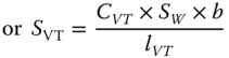
Equation (6.9b) as the aircraft yawing‐moment relation about its CG becomes:
Kn and KR1 can be obtained from Figure 6.12a,b. (Reproduced from [10].)
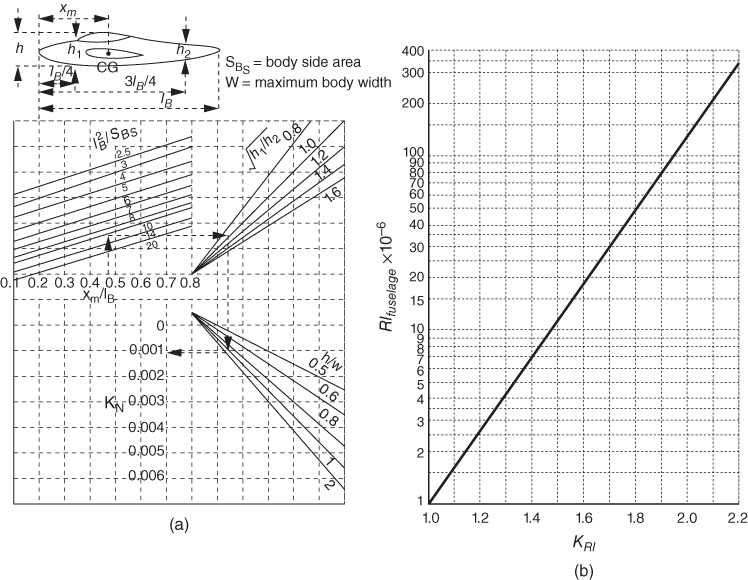
Figure 6.12 DATCOM graphs. (a) Empirical factor KN versus side slip CNβ for body + wing‐body interference and (b) effect of fuselage Re on wing‐body CNβ.
Noting that CLVT, is subjected to the side‐wash effect with angle (β + σ)
Therefore,
or
Using Eq. (6.9a,b) it can be written as follows.
DATCOM [10] gives the algebraic relation as follows.

In this book, examples of zw are small and neglected. Equation 6.15 reduces to

With the conclusion arrived at in evaluated CM_HT, the V‐tail will be sized by using the statistical data as worked out in Example 6.3.
6.7.3.1 Rudder lock
Rudder lock is an undesirable situation that can happen if the V‐tail is not properly designed. If an aircraft flies at an high sideslip angle, β, then the V‐tail can stall and lose its control authority. The powerless rudder flicks aligning with the local flow. If the fin size is relatively small compared to the rudder, then the rudder gets locked into that flicked position and the pilot will then have to apply force to reposition to regain authority. If the extent of force required is in excess of what an average pilot can exert, then control recovery will not take place endangering safety. Accidents and incidents have happened with rudder lock, some ended in fatality. It is one of the examples of the complexities involved in empennage design.
6.7.4 Aircraft Component Stability
A wing is meant to develop lift to sustain flight but is typically unstable with a destabilising nose‐down moment (−ve). The cylindrical shape fuselage also has a destabilising moment contribution. Therefore, a wing‐body combination is not flyable unless some restoring moment can be incorporated. One way is to add a horizontal with a positive nose‐up moment to an extent that makes the total aircraft stable for the full flight envelope as shown in Figure 6.13 (reproduced from [2]). Chapter 18 is dedicated to aircraft stability and may be referred to for the sign conventions.
Figure 6.13 Tail contribution to stability.
The degree of pitching moment curve slope, CMα (−ve is stable), indicates the strength of stability; the lower the value, the more relaxed the pitch stability. Commercial aircraft require a high degree of pitch stability; on the other hand, the demands of fast response for combat aircraft benefits from relaxed stability (FBW aircraft are capable of making quick manoeuvres in slightly unstable stability). Utility aircraft/small aircraft are comfortable with intermediate level of pitch stability. The following values are indicative of current designs. (Requirements for specific mission role will require CMα to suit performance capability.)
- CMα = −1.4 ± 0.2 highly stable (commercial aircraft)
- CMα = −0.8 ± 0.2 very stable (utility aircraft/small aircraft)
- CMα = −0.4 ± 0.2 relatively relaxed stability for rapid response (combat aircraft)
To size the H‐tail, it needs to produce an equal nose‐up to balance the wing‐body inherent nose‐down moment. Therefore, the wing‐body moment characteristic and the tail only moment characteristic have to be obtained.
The V‐tail moment coefficient, CN, characteristics are similar to the CM of the H‐tail, except it is free from any downwash effects. The degree of yawing‐moment curve slope, CNβ (+ve is stable), indicates the strength of stability; the lower the value, the more relaxed the pitch stability. In the case of the V‐tail, combat aircraft require good high stability to stay locked on target without swaying and have a larger rudder for rapid control response. Modern military aircraft have an FBW system architecture to ensure the best available performance. Commercial aircraft can have less than military requirements. Modern commercial transport aircraft also have an FBW control system. Even some smaller utility aircraft have some form of yaw‐damper to avoid ‘snaking’ in the demand to stay aligned with the runway.
- Commercial aircraft: ≈0.08 < CNβ < 0.16
- Utility aircraft/small aircraft: ≈0.06 < CNβ < 0.14
- Combat aircraft: ≈0.15 < CNβ < 0.3
The side force that the fuselage and V‐tail could contribute to the rolling moment is discussed in Section 18.4.2.
Wind tunnel tests/computational fluid dynamics (CFD) analyses are required to establish the wing‐body moment characteristic and the tail only moment characteristics. Nowadays, datasheets are rarely used in industry. This book uses statistical data that should offer comparable results.
6.7.5 Post Stall Behaviour
Figure 6.13 gives typical pitch stability characteristics of aircraft as a whole and component wise, showing the need for some stabilising force to keep in equilibrium in flight and controllable in manoeuvre. Figure 6.14 extends the characteristics into post stall phase of two typical modern civil aircraft examples. Post stall characteristics can only be determined through wind tunnel testing, or nowadays by CFD analyses and subsequently verified by flight tests. The behaviour varies from design to design and not easily ascertainable. The post region shows nose‐up characteristics that contribute to aircraft behaviour requiring careful design considerations to keep in safe operation.
Post stall exhibits some form of nose‐up tendencies on account that when a separated thick wing wake acts over the H‐tail, airflow becomes unsteady. Loss of wing lift and the downwash angle of attack on H‐tail results in a nose‐up pitching moment. Any asymmetry of forces about the vertical can lead into an incipient spin stage that may prove dangerous during flight tests. It is more severe in the case of high AR and low sweep wings.
Aircraft A in Figure 6.14 represents typical civil aircraft design characteristics showing CL, CD and CM variations with increasing angle of attack, α, starting from its operating range to well past stalled phase. Stall occurs at around α = 15° with rapid loss of lift, drag steadily rising and pitching moment showing pitch‐up tendencies.

Figure 6.14 Post stall moment (two typical civil aircraft examples).
Aircraft A in Figure 6.14 represents typical civil aircraft design characteristics showing CL, CD and CM variations with increasing angle of attack, α, starting from its operating range to well past stalled phase. Stall occurs at around α = 15° with a rapid loss of lift, drag steadily rising and pitching moment showing pitch‐up tendencies.
In the case of the Aircraft B, in Figure 6.14 is the tail contribution in post stall region with CM trimmed just above 30° angle of attack. In this case, the elevator loses its control authority and if enters a flat spin, recovery becomes difficult. Empennage design is rather complex and not dealt with in this book. Practising aeronautical engineers may refer to NACA TR 1339, which summarises longitudinal characteristics of a swept wing at a high Reynolds number.
6.7.6 Aerodynamic Shielding of the V‐tail
The H‐tail position relative to the V‐tail is a significant consideration; the options available are shown in Figure 6.15. It can be from the lowest position through the fuselage to the other extreme, on the top as a T‐tail. Any position in between is considered the mid‐tail position.
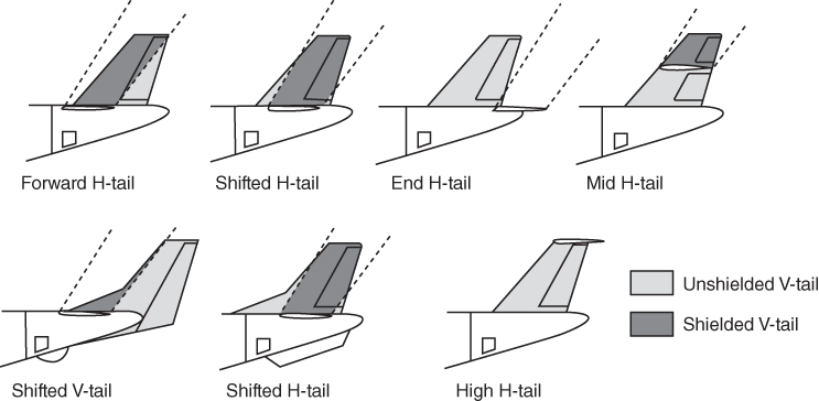
Figure 6.15 Positioning of the horizontal tail – V‐tail shielding.
Designers must ensure that the H‐tail does not shield the V‐tail. The wake (i.e. dashed lines in Figure 6.15 from the H‐tail should not cover more than 50% of the V‐tail surface and should also have more than 50% of the rudder area free from its wake to maintain control effectiveness, especially during spin and stall recoveries. Shifting the V‐tail aft with the rudder extending below the fuselage will bring the fin and rudder adequately outside the wake. A dorsal and ventral fin can bring out more fin surface outside the wake, but the rudder must be larger to retain effectiveness. Lowering the H‐tail would move the wake aft; however, if it is too low, it may hit the ground at rotation – especially if the aircraft experienced a sudden bank due to wind gusts.
6.7.7 Wing Wake on the H‐tail
Careful positioning of the H‐tail can avoid wing wake avoid interfering with H‐tail as shown in Figure 6.16. At a high angle of attack, the wing wake should avoid the H‐tail in the near‐stall condition so that the pitch control remains adequate. Stabiliser and elevator may be place away from the zone of stalled wing wake as shown in the diagram. Until the stall wing wake position can be established, the values of the angles in the figure may be taken to start with. CFD/wind tunnel test will show the position. An all‐moving T‐tail ensures higher elevator control authority to overcome any inadequacy if the tail is within the wing wake.
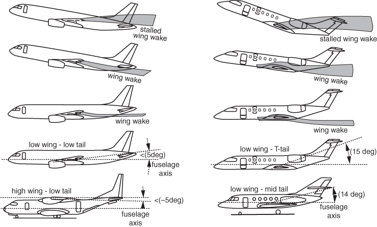
Figure 6.16 Wing wake on the H‐tail.
Care must be taken so that the H‐tail is not within the entrainment effects of the jet exhaust situated at the aft end, which is typical for aft‐mounted or within‐fuselage jet engines. A military aircraft engine is inside the fuselage, which may require a pen‐nib type extension to shield the jet‐efflux effect on the H‐tail. In that case, the H‐tail is moved up to either the midlevel or the T‐tail.
6.8 Aircraft Control System
Chapter 18 covers the analytical considerations of aircraft motion in six degrees of freedom and its control. Figure 3.8 shows a Cartesian representation of the six degrees, comprising of three linear and three rotational motions. This section offers a brief description of associated control hardware and design considerations (for more details, refer to [2–9]). Aircraft control system weight is about 1–2% of maximum takeoff weight (MTOW).
6.8.1 Civil Aircraft Control Sub‐System
The three‐axes (pitch, yaw and roll) aircraft control has evolved considerably. Use of trim tabs and aerodynamic/mass balances alleviate hinge moments of the deflecting control surfaces easing pilot work‐load. Some of the types in operation are given here.
- Wire‐pulley type. This is the basic type. Two wires per axis act as tension cables, moving over low friction pulleys to pull the control surfaces in each direction. Although there are many well designed aircraft using this type of mechanism, frequent maintenance is required to check tension level and possible fraying of wire strands. If it is in improper tension then the wires can jump out of pulleys making the system inoperable. Other associated problems are dirt getting in, the rare occasion of jamming, elastic deformation of support structures leading to loss of tension and so on. Figure 6.17 shows both the wire‐pulley (rudder and aileron) and push‐pull rod (H‐tail) types of control linkages. The push‐pull rod is described next.
- Push‐pull rod type. The problems of wire‐pulley type are largely overcome by the use of push‐pull rods to move the control surfaces. Designers must ensure that the rods do not buckle under compressive load. In general, it is slightly heavier and a little more expensive but worth installing for ease of maintenance. Many aircraft use a combination of wire‐pulley and push‐pull rod arrangements (Figure 6.17).
- Mechanical control linkage boosted by a Power Control Unit (PCU). As aircraft size increases, the forces required to move the control surfaces increase to a point when pilot work‐load crosses the specified limit. Power assistance by PCU overcomes the problem. One of the problems of using PCU is that the natural feedback feel of control forces is obscured. Then artificial feel is incorporated for finer adjustment leading to smoother flight. PCUs can be hydraulic, linear driven electric motors or rotary actuators (there are many types). Figure 18.17 is supported by PCU.
- Electro‐mechanical control system. Large aircraft can save considerable weight by replacing mechanical linkages with electric signals to drive the actuators. Aircraft with FBW use this type of control system (Figure 18.16). Currently, many aircraft routinely use secondary controls (e.g. high‐lift devices, spoilers, trim tabs etc.) driven by electrically signalled actuators.
- Active control system. Feedback control systems such as stability augmentation systems (SAS – e.g. a yaw‐damper) were routinely deployed for some time. Modern aircraft, especially combat aircraft control systems have become very sophisticated. A FBW architecture integrated with a Full Authority Digital Engine Control (FADEC) is essential to these very complex systems when aircraft can fly under relaxed stability margins (see Section 18.10). Enhanced performance requirements and safety issues have increased the design complexities incorporating various kinds of additional control surfaces. Figure 6.18 shows typical subsonic transport aircraft control surfaces.
- Optically signalled control system. The latest innovation uses optically signalled actuators. Advanced aircraft are already flying using fibreoptic lines to communicate with control systems.
6.8.2 Military Aircraft Control Sub‐System
Figure 6.19 shows the various control surfaces/areas and system retractions required for a three‐surface configuration. It can be seen that it has a lot more than modern civil aircraft have.
Military aircraft control requirements are at higher level on account of the demand for hard manoeuvres. FBW assisted controls allows aircraft to fly with small amounts of negative stability margin for rapid response. The F117 is incapable of flying without FBW. Additional controls are the canard, intake scheduling and thrust vectoring devices. Fighter aircraft may use stabilators (see Section 6.5.3) in which the elevators can move differentially to improve roll capability. Stabilators are used collectively for pitch and differentially for roll control. Also aileron and rudder can be interconnecting. There could be automatic control in parallel with the basic system.
Military aircraft with short fuselage results in a short tail arm. Therefore, to make combat aircraft capable of hard and fast manoeuvres, a large tail surface is required that may give rise to some rolling moment problems and make it heavy. It is convenient to split a single large V‐tail into a twin tail half as light (canted or vertical) as shown in Figure 6.19.
6.8.3 Reversible and Irreversible Control
Depending on the type of designs, based on the linkage between the control stick and control surface and their responses, the flight control systems are classified into two main types: (i) reversible control and (ii) irreversible control, as explained next.
Reversible control. A reversible flight control system results when force input from either side, that is, between control stick or control surface, can be felt by the other side. With a direct mechanical linkage (wire‐pulley type or push‐pull rod type – Figure 6.17) between control stick and control surface, the pilot force application is translated to control surface action to generate a hinge moment. In a similar manner, if the force is applied on the control surface, it will translate to the pilot directly leading them to experience the feel of the force on their control stick corresponding to the force on the control surface. This can be tested when the aircraft is on the ground, when pre‐flight checks of the control surface movement move the flight deck controls. Mostly, small aircraft (around 1500 kg and below) have a reversible flight control system (see Section 6.8).
Irreversible control. As aircraft size increases, the forces required to move the control surfaces increase to a point when pilot work‐load crosses the specified limit when power assisted controls are required. Various types power systems are described in Section 6.8. In the case of an irreversible flight control system, there is no direct mechanical linkage between the control stick/wheel and the flight control surface. A PCU is installed in between, delinking from manual input to more powerful mechanical output to supply the higher level of force required for control surface activation. The FBW technology is the most advanced type incorporating microprocessor‐based power assisted controls. This makes the flight control system an irreversible system. In this case, any force input on the control will not be felt by the pilot, or intervened with by the PCU or other power assistance device installed. This desensitises the pilot, being unable to gauge the extent of input required. This problem is overcome by incorporating a calibrated artificial feel (Q‐feel), simulating a reversible flight control system.
6.9 Aircraft Control Surfaces and Trim Tabs
Aerodynamic force (in this, case the lift force) on a movable control surface contributes to aircraft attitude change as an act of manoeuvre. The aerodynamic force develops a moment about the hinge of the rotating movement. Figure 6.20 shows wing and empennage control surfaces and associated trim tabs. There are two types of control surfaces, (i) primary control surfaces and (ii) secondary control surfaces. Sign conventions associated with controls deflection are given in Figure 3.11. (Section 18.6 deals with stick force.)
- Primary control surfaces for 3° of angle of rotation:
A central stick or yoke for pitch (elevator – stick movement as pull/push) and roll (aileron – stick movement sideways, right/left).
Foot operated control yaw (rudder operation – right and left operated in a linked mechanism).
Elevator and rudder constitute empennage. Various kind of empennage systems are described in Section 6.5.
(The throttle is the engine power control system.)
- Secondary control surfaces
Mainly, the secondary control surfaces supplements primary control surfaces for pilot ease by relieving pilot force, which otherwise could be high. These are trim surfaces incorporated on all primary control surfaces as required.
There are many other kind of secondary control surfaces, for example, high‐lift devices, spoilers, airbrakes and so on.
Control actuation requires pilot effort; the bigger the aircraft, the bigger are the control surfaces, requiring corresponding higher forces that can induce pilot work‐load stress. This situation shows up in aircraft as small as 2000 lb in weight. The empennage sizing must guarantee to offer adequate authority in the full flight envelope, with special attention to critical manoeuvres. Control forces are dealt with in Section 18.6.
The design objective is therefore to alleviate pilot stick (pitch and roll) and pedal forces (yaw) to an qualitatively acceptable level stipulated by the certification agencies and accepted by qualitative flight tests. For bigger and/or advanced aircraft, this is achieved by incorporating power assisted controls. The methods to relieve pilot force are by balancing control surfaces, for example, with counter weights, aerodynamically with horn balance and so on. For bigger and/or advanced aircraft, this is achieved by incorporating power assisted controls.
Here, only the concept of trimabilty is introduced to establish the incorporation of trim tabs on the control surfaces as shown in Figure 18.21. To relieve the pilot work‐load, especially when a large force is required to control, designers have discovered various methods to achieve that. An aerodynamic trim tab deflects in the opposite direction to the elevator deflection. This develops opposite elevator hinge moment to relieve some pilot (pull) force.
The analysis procedure adopted for elevators is also applicable to rudder and aileron hinge moment analyses and they also have trim tabs. Certification agencies have stipulated the limit of pilot force required in a harmonised manner for the three axes of controls. There are several methods to ways to relieve pilot forces, for example, aerodynamic mechanical and power assisted methods, as shown in Subsection 6.9.1. (Control surface instability, e.g. flutter, reversal, etc., should be avoided. These are specialised topics beyond the scope of this book.)
6.9.1 Aerodynamic Balancing of Control Forces
The design objective of balancing control force is to alleviate pilot stick (pitch and roll) and pedal forces (yaw) to an acceptable level stipulated by the certification agencies and accepted by qualitative flight tests. There are several methods to achieve this as described briefly in this subsection. It is desired that the empennage is sized and rigged in a manner such that a pilot will need to typically apply the least amount of force to actuate control deflection during the desired flight path. The empennage sizing must guarantee to offer adequate authority in the full flight envelope, with special attention to critical manoeuvres. (In this book, the control force balancing system is not designed but just introduces the possibilities to the readers. Determining hinge moments is notoriously difficult. Movable aircraft control design and sizing are topics of their own and beyond the scope of this book.)
In the following, are the main type of aerodynamic balance mechanisms shown in Figure 6.22.
- External overhang. The hinge line is moved rearward away from its nose to have the forward overhung part move down while the active rear portion aft of the hinge line rotates up to give an aircraft nose‐up pitching moment. The extent of front part from the hinge line is sized to provide an opposite force to relieve the active force on the larger part of the control surface (elevator) behind the hinge line.
- Sealed internal overhang. An innovative way to utilise the pressure field around the leading edge of the control surface. Here the overhang part is inside the wing aerofoil within a chamber and does not protrude out as in the case external overhang mentioned in point (i). This suits a thicker aerofoil of the wing with laminar flow characteristics so separation effects at the trailing edge are relatively small. Within the chamber, a sealed partition from the overhang extending from the leading edge of the control surface in enclosed with carefully placed gaps on both side, positioned to take the low pressure from the lift producing part of the curved leading edge. The differential of pressure between the upper and lower surfaces assists movement in the direction relieving pilot force.
- Trim tab. An effective way to relieve pilot force by incorporating trim tabs at the trailing edge of the control surface deflecting in the opposite direction to the control surface deflection. It is a mechanical linkage (or electrically operated) to extract the opposite moment of aerodynamic force from an additional extended surface (Figure 6.21). The linkage may be made as a fixed one or adjustable to suit pilot requirements after control is actuated (see Section 18.6).
- External aerofoil balance. Not so common in practice. The external aerofoil offers the additional force in the direction it is required.
- Bevel trailing edge. Bevelling the trailing edges of elevator increases the hinge moment in the direction of rotation to relieve pilot force [11]. Boundary layer separation at the trailing edge affects the elevator hinge moment. When the elevator is deflected downward, then airflow over its upper surface separates earlier than at the lower surface causing change in elevator hinge moment. By sharp bevelling of the elevator trailing edge, the change can be minimised, assisting the pilot.
- Frise (aileron). Ailerons are positioned at the trailing edge and at the outboard side of the wing. These are rigged in such a manner that each side deflects in opposite direction. The upward deflected side goes down on account loss of lift, while the other side moves with downward deflection: the wing goes up with the additional lift. Rolling of an aircraft by aileron activation is invariably associated with adverse yawing of aircraft in the other direction. The aerofoil of the Frise aileron is specifically shaped in such way that its lower side of the leading edge is sharper than upper side and, if required ,the hinged line is lowered. When the Frise aileron is deflected upwards, the sharp end of the overhang part ahead of hinge line protrudes outside the wing contour offering more drag than the other side of the wing, thereby reducing the yaw tendency. The overhang part also acts as balancing force, as described before. (A differential extent of deflection, that is, upward deflection more than downward is a better method to reduce adverse yaw. This also delays tip stall of the outward wing for having the aileron in a reduced angle of attack. Large aircraft incorporate a roll spoiler to increase drag on the wing, the side going down. Of course, the best method is to use a rudder for a coordinated turn without aircraft yawing.)
- Horn balance. This is like external overhang but instead of moving the hinge line aft, the free ends of the elevator tips have a ‘horn’ like extension ahead of the hinge line to relieve pilot force. It can be shielded or unshielded (Figure 6.21).
Mechanical balancing of control forces use a down‐spring and/or a bob‐weight in the linkage or on the stick itself (Figure 6.22). A properly sized moment arm to the bob‐weight load can reduce the magnitude of the weight and it is desirable to place it close to aircraft CG.
Both are meant for the same usage and can installed singly or together. These are also seen as giving a ‘feel’ of the control in terms of control force per ‘g’. For a pull up action from trimmed level flight, the down‐spring/bob‐weight resists with elevator down ‘feel’ sized to the requirement. Typically, a bob‐weight provides a higher stick force per ‘g’. Certification requirements are that the minimum stick force per g is 3 lbs per ‘g’ for a single handed stick controlled aircraft (one hand) and 4 lbs per ‘g’ for a two handed wheel controlled aircraft. The stick force gradient (Section 18.6.1) requires 1 lb force per 6 kts aircraft speed change.
But there is a difference between them. The bob‐weight under the influence of inertial load pushes the stick forward. Therefore, in high ‘g’ manoeuvre, the pilot will experience higher stick force per ‘g’ when pulled. This will not be case for spring loaded control stick and stick force per ‘g’ remains the same what spring stiffness offers.
A bob‐weight ahead of the hinge line of the control surface balances the weight of each side about its rotational axis. In this case, only the aerodynamic balancing is to be considered.
6.9.2 Power Assisted Managing of Control Forces
When aircraft becomes big enough with larger control surfaces, then a power assisted mechanical and or electric system is incorporated in the control linkage.
The mechanical circuit, which links the cockpit controls with the hydraulic circuits. Like the mechanical flight control system, it consists of rods, cables, pulleys and sometimes chains. The hydraulic circuit, which has hydraulic pumps, reservoirs, filters, pipes, valves and actuators. The actuators are powered by the hydraulic pressure generated by the pumps in the hydraulic circuit (refer to Section 6.8.1).
6.9.3 Active Control Systems
Refer to Sections 6.8.1 and 18.10.
6.10 Empennage Design
Empennage design is cost intensive, requiring generation of accurate design information; for example, the related design coefficients and derivatives required to make the analyses. Textbooks [6–9, 11] give the fundamental theories related to the role of the empennage. These detailed studies (CFD/wind tunnel) are carried out more intensively during Phase II of the project. DATCOM/Engineering Sciences Data Unit (ESDU) ([10, 12]) give empirical relations to obtain CM, CN, CL and aircraft NP, to get a satisfactory preliminary empennage. This is a time consuming lengthy procedure.
Empennage design is complex. Like any other feed‐back system analysis, control characteristics are rarely amenable to the exactness of theory due to lack of exact information of the system. Theoretical methods can produce a result but because of their limitations in modelling, the accuracy is difficult to substantiate; instead datasheet/CFD/test methods are used in industry. Datasheet methods served well until CFD analyses took over yielding better results much faster.
The empennage sizing must guarantee to offer adequate authority in the full flight envelope, with special attention to critical manoeuvres. It is important that the design should keep flying qualities within desirable levels by shaping the aircraft appropriately. Flying qualities can only be determined by actual flight tests. In a marginal situation, recorded test data could satisfy airworthiness regulations yet may not prove satisfactory to the pilots. Typically, several pilots evaluate aircraft flying qualities to iron out if there are debatable points. Flight tests start with the prototype empennage then move to fine‐tuning by tailoring and riggings through the tests. Practically all modern aircraft incorporate active control technology to improve aircraft flying qualities. This is a routine design exercise and offers considerable advantages to overcome any undesirable behaviour, which is automatically corrected all the time.
Classroom analytical study can only give representative results to understand the physics involved in designing empennages. It can be questioned to apply optimisation methods in empennage design; one of the pertinent questions is, what is the objective? Surely, flying qualities are what pilot feels and are hard to interpret analytically?
At the early stages of the conceptual design phase, use of statistical data of the past empennage sizes in the class is a good starting point. Statistical data exhibit strong correlations and the methodology is used in industry at the inception of the project when not much data are available. This is adopted in this book.
Structural considerations for an empennage joint are given in Section 19.12.
H‐tail. H‐tail design has additional constraints over wing design, as its size depends on wing and fuselage sizes and their moment characteristics. In addition, the location of aircraft CG shifts between the permissible forward‐most and aft‐most limits. For safety reasons, the H‐tail must provide stability for the aft‐most CG position, which requires a larger H‐tail size than what is required at the forward‐most CG position requiring higher force to control. Power assisted controls allow the H‐tail to be on the larger size for safe operation.
A larger H‐tail size can easily be tailored by trimming the tips. On the other hand, enlarging a smaller sized H‐tail is lot more expensive; in a difficult situation it may have to be re‐designed and then fabricated for re‐installation.
Wing position with respect to fuselage gives the H‐tail arm, LHT length, satisfying the extreme CG locations. Fuselage length is deterministic (see Section 5.9.1). The moving wing position enters into wing chasing of the CG and can become unwieldy. Reposition of the H‐tail can offer some adjustment to the H‐tail arm, LHT. Therefore, the method used here is a simple one based on the statistics of past designs.
V‐tail. The procedure for V‐tail design follows the same methodology as used in H‐tail design, this time in the yaw‐plane instead of in the pitch plane. The V‐tail, being in the plane symmetry with a symmetric aerofoil, does not produce a moment in normal flying without yaw making it relatively easier to design. It deals with CN instead of CM.
6.10.1 Simplified Empennage Design Methodology
Typical choices for the empennage design are suggested here. This is concerned with the planform area, its shape, sweep, taper ratio and twist. Cost consideration for empennage design is important. Positioning of a conventional tail is linked with the wing position with respect to the fuselage.
Although Examples 6.1 and 6.2 demonstrated the DATCOM methods, this book uses statistical data as worked out in Example 6.3. The reason for it is explained next in the two DATCOM worked‐out examples and in Section 6.7.3. Given next is a step‐by‐step approach to decide empennage planform size and shape.
- Step 1 (Find H‐tail and V‐tail areas)
- Uses tail volume coefficients from statistics to obtain the empennage areas.
- Step 2 (Decide on the aerofoil)
- An H‐tail can have a symmetric aerofoil or low camber aerofoil placed inverted to obtain a nose‐up moment at a lower incidence to the wing wake. H‐tail aerofoil t/c is comparable to wing aerofoil at MAC. Small recreational aircraft operation below 150 mph can get away with thick flat plate with rounded leading edge.
- A V‐tail has a symmetric aerofoil, with similar t/c comparable to wing aerofoil at MAC. Positioning of the V‐tail is always at the plane of symmetry, propeller driven aircraft may require 1–2° offset to counter the propeller wash in swirl and the torque reaction of the heavy propeller. V‐tail with sweep back gives an additional tail arm, lt, for a T‐tail mounted on the on the top.
- Step 3 (Decide on the planform)
- Decide the planform shape. Typically, it follows the wing planform shape but at a lower AR, that is, a tapered wing inherits a tapered planform empennage.
- Step 4 (Decide on the dihedral/anhedral, Λ and λ)
- Once H‐tail and V‐tail areas obtained, their dihedral/anhedral, Λ and λ, have to be decided. At this stage, hold empennage sweep should be no less than the wing sweep, but may increase to gain in tail arms. Keep taper ratio, λ, at around 0.25–0.5, but it may take a suitable λ ≈ 0.3.
6.10.2 Control Surfaces Design
Control surfaces, for example, elevator, rudder and aileron, are subcomponents as a part of H‐tail, V‐tail and wing, respectively. Design of these control surfaces are not dealt with in this book due to their complexities, associated with hinge moments, gaps, balancing, trim surfaces, in addition to the usual aerodynamic and CG considerations. Instead, the required areas, taken from the statistics of similar designs, are earmarked. However, to understand the physics of control surface design, only the elevator design concept is discussed as given next.
So far, the H‐tail was designed at a stick‐fixed trimmed equilibrium state of aircraft flight. The static stability characteristics of aircraft are measured in term of the slope dCM/dα, a more negative value it makes more stable. The higher the stability, the higher the stiffness requiring more power to control and its limit is specified for pilot ease. The equilibrium state of operation is when CM = 0 at a particular ‘α’ for the set‐up, that is, at a particular CL, in the example case at HSC with CL = 0.4. However, to manoeuvre, say, in pitch plane to climb, pilot will have to use the control surface elevator up (−ve upward deflection) that will change aircraft CL to a higher value as climb speed is slower than the cruise speed. Higher CL, that is, at higher α, reduces the CM as can be seen in Figure 6.13. To maintain equilibrium during climb, the aircraft setting of H‐tail needs to changed.
H‐tail setting can be adjusted by either (i) by rotating the entire H‐tail that can pose problems in subsonic operation or (ii) by rotating the aft part of the H‐tail about a hinge line as an elevator, as the conventional accepted design that is now in practically all subsonic aircraft in operation.

Figure 6.17 Wire‐pulley and push‐pull rod control system. (
Source: Courtesy of Europa‐Aircraft).
Examine the case for climb when additional lift in terms of ΔCM requires the aircraft to rotate for climb by applying the elevator up. When the rotation reaches to a steady climb, the equilibrium equation, with an H‐tail contribution, can be written in line with Eq. 6.7, given here.
where [(dCL/dα)HT] × αt × CHT is incremental downward moment ΔCm_HT developed by the upward rotation of the elevator angle by δe.
Trimming. This ΔCM_HT increment is achieved by the pilot applying force to pull the control stick to make elevator rotating upward. Climb takes time to reach the desired height that can strain a pilot by holding the stick applying force. This force can be relived with rotating a trim tab in the opposite direction built into the system (Figure 6.17). Fine‐tuning to zero force is done by the pilot by adjusting a trim wheel/switch in the cockpit.
6.10.3 Effect of Power in Moment Contribution
This is based on the position of the thrust line with respect to CG affecting the aircraft moment. Power‐on and power‐off moments will be different. Induced airflow on the H‐tail from jet blast and propeller slipstream over the H‐tail alter H‐tail moment characteristics. Power effects are not dealt with in this book.
6.11 Other Planar Surfaces
Aircraft are invariably installed with other surfaces such as the ventral fin, dorsal fin, pylon, speed brakes and so on, as described in the following subsections.
6.11.1 Ventral Fins
A good aircraft should not have a ventral fin that contributes to weight. It comes from two reasons from the inadequacy shown during flight tests, as follows.
- If there is not enough ‘weathercock’ stability on account of an inadequate fin area. An additional planar area is attached at the plane of symmetry at the aft fuselage under the belly to a size required to make up for the inadequacy of the fin size, as shown in Figure 6.23. The placement must ensure ground clearance at aircraft takeoff rotation, if required, install a wheel to protect impact.
- If the aircraft exhibits inadequate handling characteristics such as pitching problems and/or lateral oscillations, for example, a Dutch roll/swaying. Installing a pair of ventral fins (small inverted fixed Vee‐tail) in either side of the aircraft plane of symmetry, set inclined with some anhedral angle at the aft fuselage sides, as shown in Figure 6.23. The ventral chord length is considerably longer than its span and set aligned to aircraft at aircraft cruise attitude to minimise drag. Pitching problems and lateral oscillation problems have different origins, hence setting the pair of ventral fins to the fuselage has a different anhedral angle. The two cases are explained next.
When a high angle of attack, α, if the H‐tail retains pitch‐up tendency, then lift force on ventral fins on account of the angular attack offers nose‐down moments. The size and anhedral angle of ventral fins are determined by a series of flight tests in a trial and error method, CFD analyses can reduce the number of flight tests.
- In case of lateral oscillation problems, a ventral fin can minimise oscillations, the size and anhedral angle are established by a series of flight tests; in a trial and error method, CFD analyses can reduce the number of flight tests.
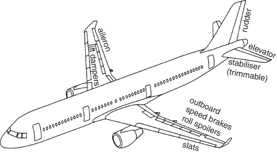
Figure 6.18 Civil aircraft control surfaces.
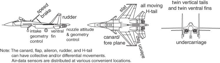
Figure 6.19 Military aircraft control surfaces.

Figure 6.20 Aircraft control surfaces. (a) Wing control and (b) empennage control.

Figure 6.21 Types of aerodynamic balancing of controls.
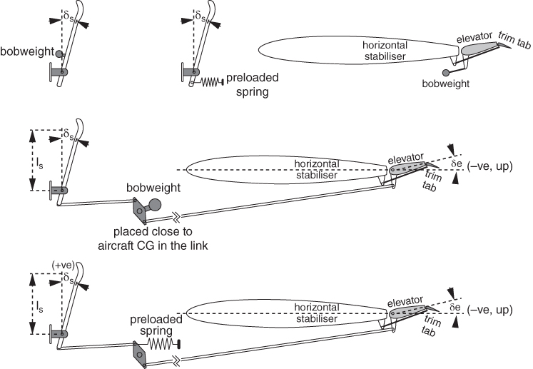
Figure 6.22 Bob‐weight and spring.
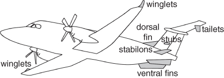
Figure 6.23 Dorsal and ventral fins.
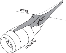
Figure 6.24 Pylon for nacelle.
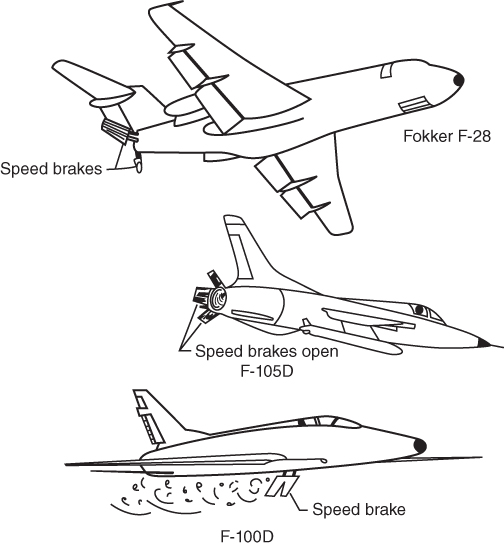
Figure 6.25 Speed brakes and dive brakes [13]. (
Source: Courtesy NASA).
Good examples incorporating ventral fins are the Learjet family, MIG21 and so on. Nowadays, incorporating FBW technology gives safety to keep aircraft within the safe flying envelope. All modern commercial transport has FBW technology. Advanced fifth generation combat aircraft have a vector thrust mechanism for both axes overcoming inadequacies that can arise in both pitch and yaw controls.
6.11.2 Dorsal Fins (LERX on the V‐tail)
Dorsal fins act in the same way as in the case of leading edge root extension (LERX)/strakes on wings. The dorsal fin is a triangular shaped planar surface (can be flat or contoured to fin the V‐tail aerofoil) installed on the fuselage in front the fin. In the case of a fin getting stalled at high angle of attack, β, making rudder ineffective and causing rudder lock (not mechanical seizure), a situation when the aircraft cannot respond to rudder deflection on account of airflow breaking away earlier at the fin surface; sometimes it may lead into a worse situation where the rudder acts in reverse. Like wing strakes (Section 4.11), the dorsal fin develops additional vortex lift covering a good part of the fin allowing an adequate part of the rudder to initiate aircraft to respond and obtain full authority eventually.
Beech 1900C presents a unique empennage design consideration. To keep cost down by retaining components commonality, the pressurised Beechcraft 1900 was derived from their earlier successful design, the Beechcraft Super King Air aircraft. In addition to having a dorsal fin and a pair of ventral fins, the Beech 1900C has another pair of stub like horizontal surfaces (known as stabilons – Figure 6.23) both in the middle of the aft fuselage plus a pair of stub like small horizontal planes in roughly the middle of the stabiliser. The T‐tail also has small vertical fin like plates (called tailets – Figure 6.23) on the lower surface close to the tip. Evidently, these are installed after analysing flight tests to enhance stability. The authors do not have the manufacturers' design philosophies but stabilons and small surfaces on the fin seem to increase the static stability margin to accommodate extended CG limits. Tailets can serve to improve an aircraft's lateral stability. This is a fine example of the complexities of empennage design; a topic that stands on its own and is beyond the scope of this book as mentioned earlier.
6.11.3 LERX on the H‐tail
Strakes (LERX) at the H‐tail play an important role just as they do on wing (see Section 4.6.1), to additional vortex lift at a high tail plane angle of attack, αht. This kind of strake comes as modification attachment in case flight tests show inadequacy in elevator authority (e.g. HAL Deepak, HPT32).
6.11.4 Pylons
Pylons are support structure and not intended to contribute aerodynamic forces other than their inherent drag. Pylons attached to the wing or fuselage carry a wide variety of loads, for example, engine nacelle pod, armament loads, electronic pods, drop tanks and so on. The case of a pylon carrying a nacelle pod is shown in Figure 6.24. To reduce interference drag between the nacelle and fuselage, sometimes it can be shaped into slight curvature (banana shape).
6.11.5 Speed Brakes and Dive Brakes
Speed brakes and dive brakes have the same definition. They are mounted specifically on the fuselage for military aircraft and as spoilers on the wings for civil aircraft. However, there are civil aircraft that use this type of device mounted on the fuselage. Speed brakes are specifically designed to reduce speed rapidly, typically on approach and in military combat manoeuvres. Care must be taken to minimise aircraft moment change when these brakes are deployed.
Speed and dive brakes are primarily drag‐producing devices positioned in those areas that will create the smallest changes in moments (i.e. kept symmetrical to the aircraft axis with the least moment arm from the CG). Figure 6.25 shows fuselage‐mounted devices.
The Boeing F22 does not have a separate dive brake. It uses the two rudders of the canted V‐tail deflected in opposite directions along with spoilers and flaps deflected upward and downward, respectively.
References
- 1. Campbell, J. P. (1945). Experimental verification of a simplified Vee‐tail theory and analysis of available data on complete models with Vee tails. NACA‐ACR‐L5A03.
- 2. Perkins, C.D. and Hege, R.E. (1988). Airplane Performance, Stability and Control. New York: Wiley.
- 3. Nelson, R.C. (1998). Flight Stability and Automatic Control, 2e. Illinois: McGraw‐Hill.
- 4. Etkin, B. (1972). Dynamics of Atmospheric Flight. Wiley.
- 5. Pamadi, B.N. (2015). Performance, Stability, Dynamics and Control of Airplanes, 3e. Reston, VA, USA: AIAA.
- 6. Anderson, J. (2011). Fundamentals of Aerodynamics SI. McGraw Hill.
- 7. Kuchemann, D. (2012). The Aerodynamic Design of Aircraft. AIAA.
- 8. Abzug, M.J. and Larrabee, E.E. (2002). Aircraft Stability and Control. Cambridge, UK: Cambridge Aerospace Press.
- 9. Seckel, E. (1964). Stability and Control of Airplanes and Helicopters. New York: Academic Press.
- 10. Fink, R. D. (1978). USAF Stability and Control, DATCOM. Report Number AFWAL‐TR‐83‐3048, Flight Dynamic Laboratory, Wright‐Patterson Air force Base, Ohio, April 1978.
- 11. Nicolosi, F., Vecchia, P.D., and Ciliberti, D. (2013). A New Vertical Tail Design Procedure for General Aviation and Turboprop Aircraft. Linkoping: University of Naples ‘Frederico II’, EWADE.
- 12. Engineering Sciences Data Unit (ESDU), IHS ESDU, 133 Houndsditch, London
- 13. Talay, T. A (1976). NASA SP‐367; Introduction to the Aerodynamics of Flight.