5
Bodies – Fuselages, Nacelle Pods, Intakes and the Associated Systems
5.1 Overview
The last chapter dealt with the pertinent aspects of the planar 3D geometries of wing design considerations. This chapter follows up with the design considerations of 3D geometries for bodies, for example, the fuselage, nacelle pods and items integral to them. The aim is to shape objects in a teardrop‐like streamlined geometry that will minimise drag generation. The purpose of such bodies is to accommodate payload, consumables, equipment and so on, and produce very little lift. Some of the bodies house engines as nacelle pods with integrated engine intake and exhaust ducts, hence they are included in this chapter. The aim is still the same; that is, to shape object in a teardrop streamlined geometry that will minimise drag generation. Bodies of revolution offer a destabilising moment. Care must be taken to keep it at an acceptable level. Making an aircraft streamlined also makes it look elegant. With engines inside the fuselage, combat aircraft have their air intake as part of the fuselage and this is dealt with in this chapter.
Some dominant geometries of fuselage, nacelles, and other bodies along with the design data are presented in order to suggest possible choices available to configure new aircraft designs and arrive at a concept definition. No analytical optimisation is carried out here as these are beyond the scope of this book. In industry, Cockpit/Flight Decks (CFDs) are used throughout to fine‐tune the external aircraft geometry. It is to be noted that, along with aerodynamic considerations to shape the component geometries, their structural considerations maintenance, repair, and overhaul (MRO) aspects will also have to be taken into account.
The chapter begins with standard definitions of the various parameters of bodies that will be used in this book. Civil and military missions differ and they are explained in detail separately. This chapter covers the following topics:
- Section 5.2: Introduction
- Section 5.3: Fuselage Geometry – Civil Aircraft
- Section 5.4: Fuselage Closures – Civil aircraft
- Section 5.5: Fuselage Fineness Ratio – Civil Aircraft
- Section 5.6: Fuselage Cross‐Section Geometry Civil Aircraft
- Section 5.7: Fuselage Abreast Seating
- Section 5.8: Fuselage Cabin Layout
- Section 5.9: Fuselage Structural Considerations
- Section 5.10: Fuselage Aerodynamics Considerations
- Section 5.11: Fuselage Pitching Moment
- Section 5.12: Nacelle Pod – Civil Aircraft
- Section 5.13: Exhaust Nozzle – Civil Aircraft
- Section 5.14: Fuselage Geometry – Military Aircraft
- Section 5.15: Pilot Cockpit/Flight Deck – Military Aircraft
- Section 5.16: Engine Installation – Military Aircraft
5.2 Introduction
The reason for making the fuselage streamlined is to minimise drag, which in turn gives a high aircraft lift to drag (lift/drag) ratio as the objective of the design. The aim is to maximise the aircraft lift‐to‐drag ratio for the mission role; for transport aircraft this is about, typically, 50% higher than fighter aircraft. It is possible to blend the wing and body where the fuselage is fused into the wing, known as Blended‐Wing‐Body (BWB) aircraft. Such aircraft have been constructed and are currently in operation, one such example is the B2 bomber (Spirit). It is meaningful to also make bodies in streamlined shape to minimise drag and if possible, extract as much lift as they can offer, no matter how small it may be. Rear‐loading fuselage shaping requires compromise to ensure that it does not adversely affect aircraft stability.
The body shapes are basically of two types; (i) fuselages and (ii) nacelles/pods/auxiliary attachments and so on. The design considerations for the fuselage are dealt with first followed by the considerations for nacelles and other bodies.
5.2.1 Generic Fuselages
The term ‘fuselage’ is derived from the French word fuselage meaning ‘spindle’ shape. All fuselages have a flight deck to serve as crew station. Fuselages of small utility, transport and military category aircraft differ according to their design specifications and mission roles. Typical differences between them are outlined in the following.
5.2.1.1 Civil Aircraft
Large transport aircraft have a long constant cross‐section, circular or close to circular in shape. However, small civil aircraft do not require a constant cross‐section. Single engine aircraft have an engine mounted at the extremities of the fuselage, jet engines are mounted at the rear. The dominant parameters in fuselage aerodynamic design are its maximum cross‐sectional area, and its front and aft‐end closure shapes. Since the cross‐section may not be exactly circular (Figure 5.1), for the main types of civil aircraft, the following definitions represent diameter (Figure 5.2 shows military fuselage cross‐sections for comparison).
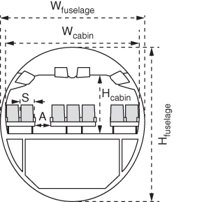
Figure 5.1 Transport aircraft fuselage cross‐section.
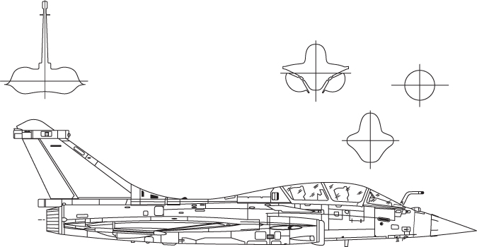
Figure 5.2 Military aircraft fuselage cross‐sections.
The equivalent cross‐sectional area of the fuselage is defined as follows.
For an elliptical cross‐section the effective diameter, Deff, is used that reduces Eq. 5.1 as follows.
Fuselages with close to circular constant cross‐sections can use the definition of average diameter, Dave‐fus, as given here.
The BWB aircraft configuration has a fuselage merged with the wing, yet it can be delineated to be dealt with as required.
5.2.1.2 Transport Category
All transport type aircraft fuselages have a circular or near circular cross‐section with a constant midsection to house the payload (passenger/cargo) and equipment. In some cases they may accommodate part of the fuel load. These fuselages have closures at both ends, for subsonic types the front end is blunter than the gradual closure at the aft, that is, a tear‐drop streamline shape (Figure 5.3a). Aft‐loading fuselages with loading ramps have a blunt aft end (Figure 5.3b).
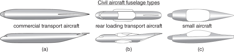
Figure 5.3 Generic fuselage shapes of civil aircraft. (a) Gradual closure. (b) Blunt end and high upsweep. (c) Varying cross‐section.
5.2.1.3 Small Aircraft Category up to Eight Seats
Small aircraft operating at low subsonic speeds do not have a long enough constant fuselage cross‐section (Figure 5.3c). They are contoured to accommodate 2–8 persons and the luggage they carry. However, the fuselage design process has the same approach as that of high subsonic aircraft to house the occupants, consumables and systems that may or may not include the engine, depending on whether there is a single or multi‐engine configuration.
5.2.1.4 Military Category Fuselage
The role of military aircraft fuselage is very different (Figures 5.2 and 5.4) and configurations differ from design to design. The supersonic aircraft front end has to have a necessarily sharp nose cone to minimise shock wave drag. This is a tightly packed housing for engines (located at the aft end), fuel and most of the aircraft systems hardware.
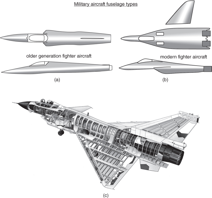
Figure 5.4 Military aircraft fuselage types. (a) Varying cross‐section (boat‐tail aft end). (b) Varying complex cross‐section. (c) Military aircraft fuselage interior Chengdu J‐10 (Source: https://www.sinodefenceforum.com).
5.2.1.5 Military Aircraft Fuselage Types
Shaping of military aircraft fuselages must have the freedom to generate variable cross‐sections to comply with the best aerodynamic contour, tightly hugging the arranged layout to house densely packed equipment (Figure 5.4). Fuel tanks and engines placed at the aft end, themselves, do not have constant cross‐sections. The their aft end closes in a boat‐tail shape with the engine nozzle exit plane at the end. In other words, military fuselages have variable crossing sections and are densely packed with power plants and their intake ducts, exhaust nozzles, electronic black boxes, radar, system equipment, undercarriage, fuel and so on. None of the definitions given in Eqs. 5.1–5.3 serve as useful other than as figures of merit for comparison.
5.2.2 Generic Nacelles Pods/Intakes/Auxiliary Bodies
Engines and their accessories/systems not buried inside fuselage need to be housed in specifically designed nacelle pods. The role of nacelle is solely meant to house the engine and its accessories and is dealt with separately. In this chapter only the external geometries are considered. The internal geometries depending on the aerodynamic considerations of air inhalation is discussed in Chapter 12 covering with aircraft propulsion.
This chapter deals with the various configuration options to consider for the choice of nacelle/intake. Military aircraft engines are fuselage mounted and hence do not have nacelles, unlike some in earlier bomber aircraft designs. Today's bomber designs, like the B2 Spirit, have engines buried into the BWB configuration.
There are other types of closed bodies of revolution, for example, drop tanks, armaments and so on that are not dealt with in this book. Their drag estimation is relatively simple. Enough information is given in the Chapter 11 on aircraft drag to evaluate auxiliary body drag.
CIVIL AIRCRAFT
5.3 Fuselage Geometry – Civil Aircraft
A civil aircraft fuselage is designed to carry revenue‐generating payloads, primarily passengers but the cargo version can also carry containers or suitably packaged cargo. It is symmetrical to a vertical plane and maintains a constant cross‐section with front and aft‐end closures in a streamlined shape. The aft fuselage is subjected to adverse pressure gradients and therefore is prone to separation. This requires a shallow closure of the aft end so that the low‐energy boundary layer adheres to the fuselage, minimising pressure drag. The fuselage can also produce a small amount of lift, but this is typically neglected in the conceptual stages of a configuration study. The following definitions are associated with fuselage geometry.
5.3.1 Aircraft Zero‐Reference Plane/Fuselage Axis
The aircraft zero‐reference and the fuselage axis are used to position and locate aircraft components to facilitate computation and manufacturing processes. They are orthogonal to each other. The aircraft zero‐reference plane is a near vertical plane, typically passes through the farthest point of the nose cone, as shown in Figures 5.5a and 5.6, but designers can choose any station for their convenience, within or outside of the fuselage.
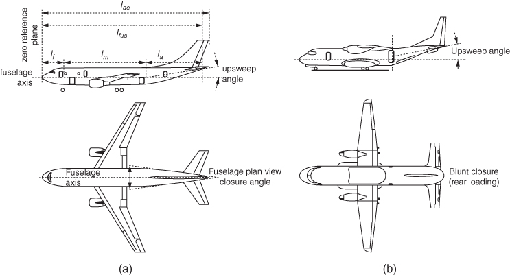
Figure 5.5 Fuselage geometrical parameters – Lengths associated with fuselages. (a) Conventional aft end. (b) Rear‐loading aft end – blunt closure.
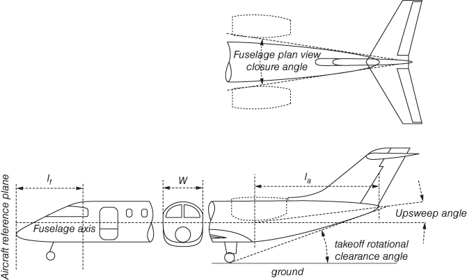
Figure 5.6 Front and aft‐end closure.
Given here are several ways to define fuselage axis as desired by the design bureau.
- Fuselage axis as a mean line of the constant cross‐sectional part of the mid‐fuselage (Figure 5.6).
- Fuselage axis passing through the nose cone if it is close to the line as defined before (Figure 5.5a).
- Fuselage axis is close to the principal inertia axis of the aircraft.
Fuselage axis may not pass through the aft‐end closure point. The fuselage axis may or may not be parallel to the ground (tail dragger aircraft is an example). If the fuselage axis is parallel to the ground then the zero‐reference plane is vertical.
The overall fuselage length, lfus consists of the (i) front‐fuselage nose cone (lf), (ii) constant cross‐section midsection barrel (lm), and (iii) aft‐end closure (la). The constant cross‐section mid‐fuselage length is established from the passenger seating capacity. The following geometrical definitions are extensively used in this book (see Figure 5.5).
5.3.2 Fuselage Length, lfus
Fuselage length, lfus, is the length along the fuselage axis, taken by measuring the length of the fuselage from the tip of the nose cone to the tip of the tail cone. This is not the same as the aircraft length, lac, as shown in Figure 5.5a. Aircraft length, lac, may not be equal to fuselage length, lfus, if any other part of the aircraft extends beyond the fuselage extremities (e.g. the tail sweep may go beyond the tail cone of the fuselage). Depending on the rated passenger capacity, the fuselage length changes in discrete steps of rows and width changes in increments of one seat pitch and width at a time.
5.3.3 Front‐Fuselage Closure Length, lf
This is the length of the front‐fuselage from the tip of the nose cone to the onset of the constant cross‐sectional barrel of the mid‐fuselage (Figure 5.5a). It encloses the pilot CFD and the windscreen, followed by the mid‐fuselage constant‐section barrel.
5.3.4 Aft‐Fuselage Closure Length, la
This starts from the end of the constant cross‐sectional barrel of the mid‐fuselage up to the tip of the tail cone (Figure 5.5a). It may enclose the last few rows of passenger seating, rear exit door, toilet, and – for a pressurised cabin – the aft pressure bulkhead, which is an important component from a structural design perspective (la > lf).
5.3.5 Mid‐Fuselage Constant Cross‐Section Length, lm
This is the constant cross‐sectional mid‐barrel of the fuselage, where passenger seating and other facilities are accommodated (including windows and emergency exit doors etc.).
5.4 Fuselage Closures – Civil Aircraft
The spindle‐shaped closure of the fuselage at both ends of the constant midsection keeps the nose cone blunter than the gradually tapered aft cone, as shown in Figure 5.6. It illustrates the front‐fuselage closure (i.e. nose cone) length, lf. Being in a favourable pressure gradient of flow, it is blunter than the aft closure. The aft‐fuselage closure (tail cone) length, la, encloses the rear pressure bulkhead with a gradual closure in an adverse pressure gradient and has some degree of upsweep. In the centre, the cross‐sectional view of the fuselage is shown.
The shaping of front and aft closures are carefully developed by analysing the pressure distribution pattern to make it as streamlined as possible for the full flight envelop. Front‐fuselage upper curvature provides pilot visibility needed to ensure that local shock formation at Mcrit is at its minimum. The aft gradual closure (as well plan view closure – Figure 5.6) needs to ensure minimum separation, having a flow energy of the thick boundary layer. The aft‐fuselage upsweep angle needs to clear the fuselage rotation angle at takeoff. Some aft fuselages may require curved upsweep.
In the past, empirical relations were used, but today's CFD analyses have made the empirical relations obsolete. For simplicity, this book uses the statistics of past designs as shown in Figure 5.7 and Tables 5.1 and 5.2.

Figure 5.7 Front (nose cone) and aft‐end closure (not to scale – various sources).
Table 5.1 Fuselage closure parameter (see Figure 4.16 – nomenclature at the bottom).
| Aircraft | L (m) | D (m) | H – (m) | W – (m) | H/W | Lf/D | La/D | UA | CA |
| A300‐600 (TA, TF, LW) | 53.62 | 5.64 | 5.64 | 5.64 | 1 | 1.6 | 3.103 | 5 | 9 |
| A310‐300 (TA, TF, LW) | 46.66 | 5.64 | 5.64 | 5.64 | 1 | 1.6 | 3.4 | 5 | 11 |
| A320‐200 (TA, TF, LW) | 37.57 | 3.96 | 3.96 | 3.96 | 1 | 1.5 | 3.4 | 4 | 8 |
| A330‐300 (TA, TF, LW) | 59 | 5.64 | 5.64 | 5.64 | 1 | 1.82 | 3.64 | 8 | 11 |
| A340‐600 (TA, TF, LW) | 59.39 | 5.64 | 5.64 | 5.64 | 1 | 1.6 | 3.32 | 8 | 9 |
| A380 (TA, TF, LW) | 70.4 | 7.78 | 8.41 | 7.14 | 1.5 | 3.91 | 5 | 11 | |
| Boeing737 (TA, TF, LW) | 31.28 | 3.95 | 4.11 | 3.79 | 1.10 | 2.80 | 7 | 15 | |
| Boeing747 (TA, TF, LW) | 68.63 | 7.3 | 8.1 | 6.5 | 1.35 | 3.31 | 5 | 11 | |
| Boeing757 (TA, TF, LW) | 45.96 | 4.05 | 4.0 | 4.10 | 1.64 | 2.91 | 6 | 13 | |
| Boeing767 (TA, TF, LW) | 47.24 | 5.03 | 5.03 | 5.03 | 1 | 1.17 | 2.67 | 7 | 15 |
| Boeing777 (TA, TF, LW) | 63.73 | 6.2 | 6.2 | 6.2 | 1 | 1.23 | 2.85 | 7 | 13 |
| MD11 (TA, TF, LW) | 58.65 | 6.02 | 6.02 | 6.02 | 1 | 1.45 | 2.82 | 5 | 13 |
| Tupolev 204 (TA, TF, LW) | 46.1 | 3.95 | 3.8 | 4.1 | 1.46 | 2.96 | 5 | 9 | |
| Fokker 100 (TA, TF, LW) | 32.5 | 3.3 | 3.05 | 3.49 | 1.42 | 3.42 | 2 | 10 | |
| Dornier 728 (TA, TF, LW) | 27.03 | 2.56 | 2.05 | 3.25 | 1.34 | 2.6 | 5 | 13 | |
| Dornier 328 (RA, TF, LW) | 20.92 | 2.42 | 2.425 | 2.415 | 1.27 | 2.64 | 5 | 10 | |
| Dash8 Q400 (RA, TP, HW) | 25.68 | 2.07 | 2.03 | 2.11 | 1.71 | 3.22 | 4 | 9 | |
| Bae RJ85 (RA, TP, HW) | 28.55 | 3.56 | 3.56 | 3.56 | 1 | 1.46 | 2.62 | 4 | 12 |
| Skyvan (RA, TP, HW) | 12.22 | square | 2.2 | 2.2 | 0.95 | 2.0 | 9 | 0 | |
| Cessna 560 (BJ, TF, LW) | 15.79 | 5.64 | 5.64 | 5.64 | 1 | 2.05 | 2.91 | 2 | 8 |
| Learjet 31A (BJ, TF, LW) | x | 5.64 | 1.63 | 1.63 | 2.17 | 3.64 | 2 | 5 | |
| Cessna 750 (BJ, TF, LW) | 21 | 1.8 | 1.8 | 1.8 | 1 | 2.00 | 3.00 | 7 | 15 |
| Cessna 525 (BJ, TF, LW) | 14 | 1.6 | 1.6 | 1.6 | 1 | 2.00 | 2.56 | 7 | 13 |
| Learjet 45 (BJ, TF, LW) | 5.64 | 1.75 | 1.72 | 1.91 | 2.86 | 8 | 4 | ||
| Learjet 60 (BJ, TF, LW) | 17.02 | 3.96 | 1.96 | 1.96 | 1 | 1.91 | 2.82 | 2 | 5 |
| CRJ 700 (RA, TF, LW) | 2.69 | 2.69 | 2.69 | 1 | 1.60 | 3.15 | 5 | 12 | |
| ERJ 140 (RA, TF, LW) | 26.58 | 2.00 | 2.89 | 3 | 14 | ||||
| ERJ 170 (RA, TF, LW) | 29.9 | 3.15 | 3.35 | 2.95 | 1.56 | 2.67 | 3 | 13 | |
| C17 (MT, TF, HW) | 49.5 | 6.85 | 6.85 | 6.85 | 1 | 0.85 | 3.41 | 10 | 12 |
| C130 (MT, TF, HW) | 34.37 | 4.33 | 4.34 | 4.32 | 0.95 | 2.56 | 9 | 12 |
TA – Transport Aircraft; LW – Low Wing; H – Fuselage Height; RA – Regional Aircraft; HW – High Wing; W – Fuselage Width; BJ – Business Jet; L – Fuselage Length; Lf – Front closure length; MT – Military Transport; D – Fuselage Diameter; Lf – Aft closure length; TF – Turbofan; UA – Upsweep angle, deg; TP – Turboprop; CA – Closure angle, degree.
Table 5.2 Fuselage front and aft closure ratios (no rear door).
| Seating abreast | Front‐fuselage closure ratio, Fcf | Aft‐fuselage closure ratio, Fca | Aft closure angle – degrees |
| ≤3 | ≈1.7–2 | ≈2.6–3.5 | ≈5–10 |
| 4–6 | ≈1.5–1.8 | ≈2.5–3.75 | ≈8–14 |
| ≥7 | ≈1.5–1.7 | ≈2.5–3.75 | ≈10–15 |
5.4.1 Front (Nose Cone) and Aft‐End Closure
The front‐end closure of bigger aircraft appears to be blunter than on smaller aircraft because the nose cone is sufficiently spacious to accommodate pilot positioning and instrumentation. A kink appears in the windscreen mouldlines of the fuselage to fit flat glasses on a curved fuselage body; flat surfaces permit wiper installation and are less costly to manufacture. Some small aircraft have curved windscreens that permit smooth fuselage mouldlines.
The aft‐end closure is shallower to minimise airflow separation when the boundary layer becomes thicker. All fuselages have some upsweep for aircraft rotational clearances at takeoff. Designers must configure a satisfactory geometry with attention to all operation and structural requirements (e.g. pilot vision polar, pressure‐bulkhead positions and various doors).
5.4.2 Fuselage Upsweep Angle
In general, the fuselage aft end incorporates an upsweep (Figure 5.6) for ground clearance at rotation on takeoff. The upsweep angle is measured from the fuselage axis to the mean line of aft‐fuselage height. It may not be a straight line if the upsweep is curved like a banana; in that case, it is segmented to smaller straight lines. The rotation clearance angle is kept to 12–16°; however, the slope of the bottom mouldline depends on the undercarriage position and height. Rear‐loading aircraft have a high wing with the undercarriage located close to the fuselage belly. Therefore, the upsweep angle for this type of design is high. The upsweep angle can be seen in the elevation plane of a three‐view drawing. There is significant variation in the upsweep angle among designs. A higher upsweep angle leads to more separation and, hence, more drag.
5.4.3 Fuselage Plan View Closure Angle
The closure angle is the aft‐fuselage closure seen in a plan view of the three‐view drawing and it varies among designs. The higher the closure angle, the greater the pressure drag component offered by the fuselage. In rear‐loading aircraft, the fuselage closes at a blunt angle; combined with a large upsweep, this leads to a high degree of separation and, hence, increased pressure drag. A finer aft closure angle is desired, but for larger aircraft the angle increases and attempts are made to keep length Lf to an acceptable level to save weight and cost.
A finer aft closure angle is desired; however, for larger aircraft, the angle increases to keep the length (Lf) to an acceptable level to reduce weight and cost.
Figure 5.7 shows several examples of current types of commercial transport aircraft designs [1]. Statistical values for the front‐ and aft‐fuselage closure are summarised in Table 5.1. There are special designs that may not fall in this generalised table. Designers may exercise their own judgement in making a suitable streamline shape to allow for an upsweep to clear for aircraft rotation at takeoff.
Table 5.1 lists the front and aft‐fuselage closure statistics. The front‐fuselage closure ratio is Fcf ≈ 1–2 and aft‐fuselage closure ratio is Fca ≈ 2–4.
Define:
Table 5.2 gives typical guidelines for the fuselage front and aft‐end closure ratios (Eq. 5.4) – the range represents the current statistical values.
5.5 Fuselage Fineness Ratio (FR)
Fuselage configuration is dictated by the aircraft mission specifications. Fuselage geometry is deterministic as its volume requirement is established from the aircraft mission (payload‐range) specification, as will be shown in Chapter 8. The aerodynamic task for fuselage shaping is to minimise drag and pitching moment for the volume required to accommodate the required items, depending whether it is a civil or military aircraft. A useful fuselage (also applied to a nacelle) design parameter is the FR (also known as the Slenderness Ratio) and is defined next.
Using Eq. 5.3, the fuselage FR is defined as,
From test data, empirical relations give aerodynamically optimum values for a realistic FR as above 16. Yet, no aircraft has been built with that long and slender a fuselage, so as to avoid adverse structural issues that may creep in. (Readers are recommended to refer to Section 2.5.1 on the role of optimisation that has to be understood for applying the process in fuselage design.) Statistics of existing designs give FR to be within 8–15 for subsonic transport aircraft (see Table 5.3 and Figure 5.8).
The high subsonic commercial transport aircraft fuselage section is basically a circular or near circular constant cross‐sectional tube with a blunt front end and tapered aft end closure. Table 5.3 lists fuselage FR values between ≈8 and ≈15. Making it shorter or longer is associated with problems arising from aerodynamic and structural issues. Aft‐loading blunt end fuselages invariably associate with some of these problems when ventral fins are installed to improve flow instability.
Table 5.3 Number of passenger versus number of abreast seating and fineness ratio.
| Baseline aircraft | Passenger capacity | Abreast seating | Fuselage Diaave (m) | Length (m) | Fineness | Cross‐section |
| Learjet 45 | 6 (4–8) | 2 | 1.75 | 17.2 | ≈10 | circular |
| Dornier 228 | 18 | 2 | ≈ | rectangular | ||
| Dornier 328 | 24 | 3 | 2.2 | 20.92 | ≈ | circular |
| ERJ135 | 37 | 3 | 2.28 | 24.39 | ≈10.7 | circular |
| ERJ145 | 50 | 3 | 2.28 | 27.93 | ≈12.25 | circular |
| Canadair CL600 | 19 | 4 | 2.69 | 18.77 | ≈7 | circular |
| Canadair RJ200 | 50 | 4 | 2.69 | 24.38 | ≈9.06 | circular |
| Canadair RJ900 | 86 | 4 | 2.69 | 36.16 | ≈13.44 | circular |
| Boeing717 | 117 | 5 | 3.34 | 35.34 | ≈10.28 | non‐circular |
| BAe145 (RJ100) | 100 | 5 | 3.56 | 30 | ≈8.43 | circular |
| Airbus318 | 107 | 6 | 3.96 | 30.5 | ≈7.7 | circular |
| Airbus321 | 185 | 6 | 3.96 | 44 | ≈11.1 | circular |
| Boeing737–100 | 200 | 6 | 3.66 | 28 | ≈7.65 | non‐circular |
| Boeing737–900 | 200 | 6 | 3.66 | 42.11 | ≈11.5 | non‐circular |
| Boeing757–300 | 230 | 6 | 3.66 | 54 | ≈14.7 | highest ratio |
| Boeing767–300 | 260 | 7 | 5.03 | 53.67 | ≈10.7 | circular |
| Airbus330–300 | 250 | 8 | 5.64 | 63 | ≈11.2 | circular |
| Airbus340–600 | 380 | 8 | 5.64 | 75.3 | ≈13.35 | circular |
| Boeing777–300 | 400 | 9 | 6.2 | 73.86 | ≈11.9 | circular |
| Boeing747–400 | 500 | 10 | ≈6.5 | 68.63 | ≈10.55 | partial double deck |
| Airbus380 | 600 | 10 | ≈6.7 | 72.75 | ≈10.8 | fully double deck |
It must be stressed that the transport aircraft product line should be offered in a family of variants to cover a wide market demand, at lower unit cost, by maintaining component commonalities. The fuselage length is extended or shortened to arrive at variant designs in the family, that is, having different FRs in the family of variants. The baseline aircraft FR may be kept around 10.
Supersonic commercial transport aircraft necessarily have high FR (above 20) to deal with supersonic wave drag. Supersonic fuselage aircraft weight per passenger is considerably higher compared to subsonic fuselage with the same passenger capacity.
Table 5.3 lists the FRs of some of the existing designs [1]. A good value for commercial transport aircraft design is 10 ± 2. The B757‐300 has the highest FR at 15.7.
Figure 5.8 summarises the statistics of fuselage FR for the abreast seating arrangement. It is to be noted that current International Civil Aviation Organization (ICAO) limit on fuselage length is 80 m. This limit is an artificial one based on current airport infrastructure size and handling limitations. To get better resolution, readers are recommended to plot a similar graph, collecting data for as many aircraft by category of aircraft in the project under study. This will serve to check aircraft configured in project work, as worked out in Chapter 8.

Figure 5.8 Abreast seating versus number of passengers (standard configuration) and fineness ratio.
5.6 Fuselage Cross‐Sectional Geometry – Civil Aircraft
Fuselage cross‐sectional geometry is not only concerned with aerodynamic considerations but also internal arrangement design considerations. This section only deals with the transport category of aircraft.
5.6.1 Fuselage Height, H
This is the maximum distance of the fuselage from its underside (not from the ground) to the top in the vertical plane (Figure 5.9).
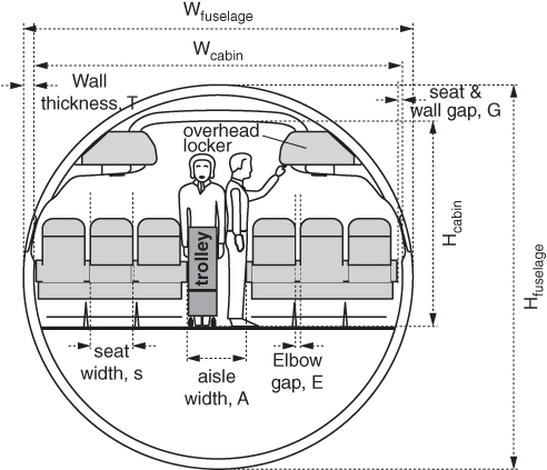
Figure 5.9 Fuselage cross‐section geometrical parameters.
5.6.2 Fuselage Width, W
This is the widest part of the fuselage in the horizontal plane. For a circular cross‐section, this is the diameter shown in Figure 5.9.
5.6.3 Average Diameter, Dave
For a non‐circular cross‐section, this is the average of the fuselage height and width at the constant cross‐section barrel part (Dave = (H + W)/2). Sometimes this is defined as Deffective = √(H*W); another suitable definition is Dequivalent = perimeter/2π. This book uses the first definition.
5.6.4 Cabin Height, Hcab
This is the internal cabin height from the floor, as shown in Figure 5.9.
5.6.5 Cabin Width, Wcab
This is a the internal cabin width, as shown in Figure 5.9.
5.6.6 Pilot Cockpit/Flight Deck
This is a term used for the enclosed space for the flight crew in the front‐fuselage. Chapter 15 describes the flight deck in more detail.
5.6.7 Cabin Interior Details
Details of cabin interior details, such as the seat details/pitch, passenger amenities and so on.
5.7 Fuselage Abreast Seating – Civil Aircraft
The minimum number of seats abreast is one row, which is not a practical design – one would have to crawl into the cabin space. There must be at least two‐abreast seating (e.g. Beech 200 and Learjet 45); the largest to‐date is the 10‐abreast seating arrangement with two aisles in the wide‐bodied Boeing747 and Airbus380. The two‐aisle arrangement is convenient for wider body six‐abreast seating.
Currently, transport aircraft abreast seating is of two kinds as follows. All fuselage cross‐sections are symmetrical to the vertical plane.
- Narrow body – up to six abreast seating with one aisle. The abreast seating is designated as an X‐X arrangement (Figure 5.10).
- Wide body – more than six abreast seating with two aisles. The abreast seating is designated as an X‐X‐X arrangement. BWB layout arrangement has the possibility of having more than two aisles (Figure 5.11).
The hyphens represent aisles and Xs are the clusters of seats. In general, aircraft with four‐abreast seating and more have space below the cabin floor for baggage and cargo.
As passenger capacity exceeds six hundred (if not in a double‐deck arrangement), the fuselage depth allows an attractive design with BWB when more than two aisles are possible. A BWB military combat aircraft has been successfully designed but its high‐capacity civil aircraft version awaits development, delayed primarily by the technology‐development and airport‐infrastructure limitations; the market has yet to evolve as well.
5.7.1 Narrow Body
Single‐aisle passenger seating arrangements are called narrow‐bodied transport aircraft. A ‘3–3’ arrangement indicates that it is a narrow‐bodied aircraft, has one aisle and has total of six seats in a cluster of three seats at each window. Figure 5.10 shows the various options for an aircraft fuselage cross‐section to accommodate different cabin seating arrangements from two‐ to six‐abreast seating in a row.

Figure 5.10 Typical narrow body single‐aisle civil aircraft fuselage cross‐sections (not to scale).
5.7.2 Wide Body
When the seating number is increased to more than six abreast, the number of aisles is increased to two to alleviate congestion in passenger movement. More than one aisle (currently two, but possible may grow to three) is regarded as wide‐bodied transport aircraft. For example a ‘3‐4‐3’ arrangement indicates that it is a wide‐bodied aircraft has a total of 10 seats with two aisles and a cluster of three seats at each window side with a cluster of four seats in the centre flanked by two aisles.
Because of the current fuselage‐length limitation of 80 m, larger‐capacity aircraft have a double‐deck arrangement (e.g. the B747 and the A380). Figure 5.11 shows options for typical wide‐body and double‐deck aircraft fuselage cross‐sections to accommodate different cabin seating arrangements from seven‐ to 10‐abreast seating in a row.
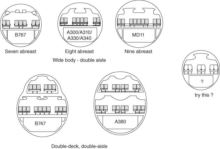
Figure 5.11 Typical wide‐body double‐aisle civil aircraft fuselage cross‐sections (not to scale).
It is interesting to study a six‐abreast wide‐body seating in 2‐2‐2 arrangement with only a 19 in. increase in fuselage diameter by having two 20 in. width aisles (Figure 5.11). This eliminates a centre seat, offering better comfort, easy movement, rapid evacuation and so on, possibly with a roughly 5% (not computed) increase in Direct Operating Cost (DOC): this should appeal to customers, both the operators and passengers.
5.7.3 More than Two Aisles ‐ Blended Wing Body
A three‐aisle arrangement with 10‐abreast seating would eliminate the cluster of four seats together. A BWB would have more than two aisles; there is no reason to not consider a triple‐deck arrangement. Figure 5.12 shows various options for futuristic aircraft fuselage cross‐sections to accommodate different cabin seating arrangements.
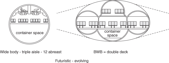
Figure 5.12 Various options for futuristic aircraft fuselage cross‐sections.
5.8 Cabin Seat Layout
There are two parameters of size: fuselage width W and fuselage length lf, which determine the constant‐section fuselage‐barrel length. In turn, this depends on the seat pitch and width for the desired passenger comfort level. Fuselage geometry is determined from the designed passenger capacity (see Figure 5.8 and Table 5.3). This is a typical relationship between the number of passengers and the number of abreast seating – a new design would be similar. The width and length of the fuselage must be determined simultaneously, bearing in mind that the maximum growth potential in the family of variants cannot be too long or short and keeping the FR at 7–14 (a good baseline value is around 10).
The first task is to determine the abreast seating for passenger capacity. The standard practice for seat dimensions is to cater to the 95th percentile of European men. Dimensions of seat pitch and width at various comfort level is given in Table 7.2. Elbowroom is needed on both sides of a seat; in the middle seats, it is shared. Typical elbowroom is from 1.5 to 2 in. for economy class and double that for first class. In addition, there is a small space between the window elbowrest and the fuselage wall, larger for more curved smaller aircraft – typically about an inch. A wider cabin provides more space for passenger comfort at an additional cost and drag. A longer seat pitch and wider seats offer better comfort, especially for oversized people. Fuselage width is the result of adding the thickness of the fuselage structural shell and soft wall furnishings to the cabin width. During Phase II (i.e. the project‐definition stage), when sufficient structural details emerge, the interior‐cabin geometric dimensions are defined with better resolution; the external geometry remains unaffected. The number of abreast seating and total passenger capacity determine the number of rows.
The first parameter to determine for the fuselage average diameter is the number of abreast seating for passenger capacity. There is an overlap on choice for the midrange capacity in the family of design; for example, an A330 with 240–280 passengers has seven‐abreast seating whereas the same passenger capacity in a B767 has eight‐abreast seating. When seating number is increased to more than six abreast, the number of aisles is increased to two to alleviate congestion in passenger movement. Because of the current fuselage‐length limitation of 80 m, larger‐capacity aircraft have a double‐deck arrangement (e.g. the B747 and the A380). It would be interesting to try a two‐aisle arrangement with six‐abreast seating that would eliminate a middle seat.
Typical geometric and interior details for aircraft with two‐ to 10‐abreast seating accommodating from 4 to 600 passengers with possible cabin width, fuselage length, and seating arrangements are described in this subsection and shown in Figures 5.13 and 5.14. The public domain has many statistics for seating and aisle dimensions relative to passenger number, cabin volume and so forth. The diagrams in this section reflect current trends. Figures 5.13 and 5.14 show the spaces for toilets, galleys, wardrobes, attendant seating and so forth, but these are not indicated as such. There are considerable internal dimensional adjustments required for the compromise between comfort and cost.
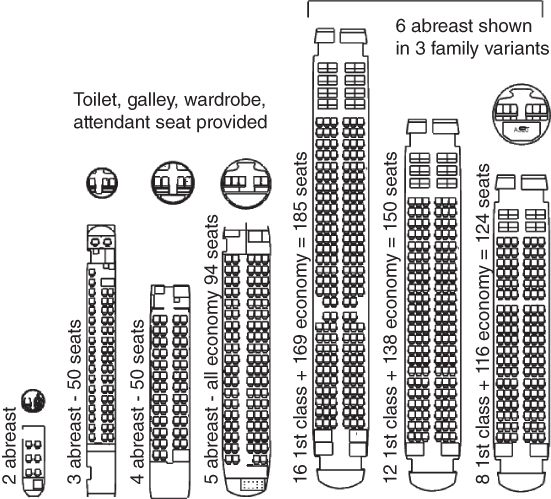
Figure 5.13 Narrow body, single‐aisle fuselage layout (not to scale).

Figure 5.14 Wide‐body, double‐aisle fuselage layout (not to scale).
Source: Reproduced with permission from Cambridge University Press.
Dimensions listed in Tables 5.4 and 5.5 are estimates for narrow‐ and wide‐body aircraft. The figures of seat pitch, seat width and aisle width are provided as examples of what exists on the market. The dimensions in the tables can vary to a small extent, depending on customer requirements.
Table 5.4 Fuselage seating dimensions – narrow body – all dimensions are in inches. Medium comfort level. Refer to Figure 5.10 for the symbols used.
| Two‐abreast | Three‐Abreast | Four‐abreast | Five‐abreast | Six‐abreast | |
| (1–1) | (1–2) | (2–2) | (2–3) | (3–3) | |
| Seat width, B (LHS) | 19 | 19 | 2 × 18 | 2 × 18 | 3 × 18 |
| Aisle width, A | 17 | 18 | 19 | 20 | 21 |
| Seat width, B (RHS) | 19 | 2 × 19 | 2 × 18 | 3 × 18 | 3 × 18 |
| Total elbow room | 4 × 1.5 | 5 × 1.5 | 6 × 1.5 | 7 × 2 | 8 × 2 |
| Gap between wall and seat, G | 2 × 1.5 | 2 × 1 | 2 × 1 | 2 × 0.5 | 2 × 0.5 |
| Total cabin width, Wcabin | 64 | 85 | 102 | 126 | 141 |
| Total wall thickness, T | 2 × 2.5 | 2 × 4 | 2 × 4.5 | 2 × 5 | 2 × 8.5 |
| Total fuselage width, Wfuselage | 69 | 93 | 111 | 136 | 151 |
| Cabin height, Hcabin | 60a | 72 a | 75 | 82 | 84 |
| Typical fuselage height, Hfus | 70 | 85 | 114 | 136 | 151 |
aRecessed floor.
Table 5.5 Fuselage seating dimensions – wide body. Medium comfort level. Refer to Figure 5.9 for the symbols used.
| Seven‐abreast | Eight‐abreast | Nine‐abreast | Ten‐abreast | |
| (2‐3‐2) | (2‐4‐2) | (2‐5‐2) | (3‐4‐3) | |
| Seat width, B (LHS) | 2 × 19 | 2 × 19 | 2 × 19 | 3 × 19 |
| Aisle width, A | 22 | 22 | 22 | 22 |
| Seat width, B (centre) | 3 × 19 | 4 × 19 | 5 × 19 | 4 × 19 |
| Aisle width, A (RHS) | 22 | 22 | 22 | 22 |
| Seat width, B (RHS) | 2 × 19 | 2 × 19 | 2 × 18 | 3 × 19 |
| Total elbow room | 9 × 1.5 | 10 × 1.5 | 11 × 1.5 | 12 × 1.5 |
| Gap between wall and seat, G | 2 × 0.5 | 2 × 0.5 | 2 × 0.5 | 2 × 0.5 |
| Total cabin width, Wcabin | 192 | 212 | 232 | 253 |
| Total wall thickness, T | 2 × 6 | 2 × 8.5 | 2 × 7 | 2 × 8.5 |
| Total fuselage width, Wfuselage | 204 | 225 | 246 | 268 |
| Cabin height, Hcabin | 84 | 84 | 84–86 | 84–86 |
| Typical fuselage height, Hfus | 204 | 225 | 246 | 268 |
5.8.1 Narrow‐Body, Single‐Aisle Aircraft
Figure 5.13 shows a typical seating arrangement for a single‐aisle, narrow‐body aircraft with two to six passengers abreast and seating carrying up to about 220 passengers (all economy class). Sections 5.4 and 5.5 give the general considerations of closure angles and FR. Table 5.4 provides typical dimensions for establishing narrow‐body fuselage widths. Details of seat, internal facilities and doors, and so on for each type are given subsequently.
5.8.1.1 Two Abreast (4–24 Passengers)
Two‐abreast seating is the lowest arrangement. The 10‐passenger capacity extends from 4 to 19 (e.g. Beech 1900D) and could expand to 24 passengers in an extreme derivative version. Current regulations do not require a cabin crew for up to 19 passengers, but some operators prefer to have one crew member, who uses a folding seat secured in a suitable location. An expanded variant of two‐abreast seating can exceed 19 passengers, but a new high‐capacity design should move into three‐abreast seating, described next. The baggage area is at the rear, which is the preferred location in smaller aircraft. Also, it is preferred to have a toilet at the rear.
5.8.1.1.1 Summary
Typical two‐abreast seating (1‐1 abreast seating arrangement) could be as follows:
- Cabin width. This consists of one seat on each side of the centre aisle. To avoid tightness of space in a smaller aircraft, seats could be slightly wider, sacrificing aisle width where there is little traffic. Typically, cabin width is between 64 and 70 in.
- Cross‐section. Fuselage cross‐section is typically circular or near circular (overall width > height). Designers will have to make compromise the choice to maximise sale. The bottom half could open up for better leg room. There is no payload space below the floor but it can be used for aircraft equipment/fuel storage. Luggage space is at the aft fuselage.
- Front/aft Closure. See Table 5.1 for the desirable range of dimensions.
- Fuselage length. This depends on the number of passengers and facilities provided.
- Seat pitch. See Table 7.2 gives the dimensions for comfort level. Medium comfort level is at 30 in. This determines the fuselage midsection length. Add front and aft closures to the midsection.
- Family variants. Addition/subtraction of fuselage plugs to a maximum of four rows conveniently distributed on each side of the wing is possible. The worked‐out example baseline version starts with 10 passengers (Section 8.9).
5.8.1.2 Three Abreast (24–50 Passengers)
A typical three‐abreast (2‐1) seating arrangement accommodates 24–45 passengers, but variant designs change that from 20 to 50 passengers (e.g. ERJ145). Full standing headroom is possible; for smaller designs, a floorboard recess may be required (see Figure 5.9). A floorboard recess could trip passengers when they are getting to their seat. Space below the floorboards is still not adequate for accommodating any type of payload. Generally, space for luggage in the fuselage is located in a separate compartment at the rear but in front of the aft pressure bulkhead (the luggage compartment door is sealed). A toilet is provided at the aft end.
Note: At least one cabin crew is required for up to 30 passengers. Above this number, two cabin crew members are required for up to 50 passengers. A new design with potential to grow to more than 50 passengers should start with four‐abreast seating described in the next section.
5.8.1.2.1 Summary
- Cabin width. This comprises of two in a cluster and one seat arrangement on each side of the aisle. The aisle width could also be increased to ease cabin crew access. Cabin width is kept within 82–88 in. depending upon customer demand for comfort level.
- Cross‐section. Fuselage cross‐section is typically circular but will follow cabin‐section contour with added wall thickness. There is no payload space below the floor but can be used for aircraft equipment/fuel storage.
- Front/aft Closure. See Table 5.1 for the desirable range of dimensions.
- Fuselage length. This depends on the number of passengers and facilities provided.
- Seat pitch. See Table 7.2 gives the dimensions for comfort level. Medium comfort level is at 30 in. This determines the fuselage midsection length. Add front and aft closures to the midsection.
- Family variants. Addition/subtraction of fuselage plugs to a maximum of five rows, conveniently distributed on each side of wing. The baseline version could start with 36 passengers with the least being 24 and the most 50 passengers.
5.8.1.3 Four Abreast (Around 44–80 Passengers)
A typical four abreast (2‐2) seating arrangement accommodates 44–80 passengers but variant designs could extend from 40 to 96 passengers (Canadair CRJ1000 and the Canadair CL‐600 is an executive version that can take 19 passengers – another example of a derivative). Cabin crew increases to at least three for higher passenger loads. Increase in fuselage diameter can offer below‐floor space for payload usage, but it is still on the tight side. To maximise below‐floor space, fuselage height could be in a slightly oval shape, the upper lobe kept semicircular and the bottom half elongated to suit smaller container sizes. Note the facilities and luggage compartment arrangement. As fuselage radius is increased, the gap between the elbowrest and fuselage wall can be reduced to 1 in. (2.54 cm) each side and seat width increased.
5.8.1.3.1 Summary
- Cabin width. Four abreast is arranged as two seats in a cluster on both the sides of centre aisle. Cabin width is kept within 100 to 106 in. depending upon customer demand for the comfort level. The aisle width could also be increased to ease cabin crew access and passenger traffic.
- Cross‐section. The fuselage cross‐section is typically circular but can be elongated. It follows the cabin‐section contour with added wall thickness (see Table 8.1). Full standing headroom is easily achievable. There is aft‐fuselage luggage space.
- Front/aft closure. See Table 5.1 for the range of dimensions.
- Fuselage length. This depends on number of passengers and facilities provided.
- Seat pitch. See Table 7.2 gives the dimensions for the comfort level. Medium comfort level is at 30 in. This determines the fuselage midsection length. Add front and aft closures to the midsection.
- Family variants. Addition or subtraction of fuselage plugs, to a maximum of seven rows, conveniently distributed on each side of the wing, is possible. The baseline version could start with 60 passengers and range from 40 to 96 passengers.
5.8.1.4 Five Abreast (80–150 Passengers)
A typical five‐abreast (3‐2) seating arrangement can accommodate 85–130 passengers, but variant designs could extend that number somewhat on both sides. The number of cabin crew increases with passenger capacity. There are not many aircraft with five‐abreast seating because the increase from four abreast to six abreast better suited market demand. A prominent five‐abreast design is the MD‐9 series (now the Boeing717).
The fuselage diameter widens to provide more generous space. Space below the floorboards is conspicuous to accommodate standard containers (see Section 7.7.6). The fuselage aft closure could affect seating – that is, the last row could be reduced to four abreast. To ease cabin access, the aisle width widens to at least 20 in. plus the armrest at each side. To maximise the below‐floor space, the fuselage could be slightly elongated, with the bottom half stretched to accommodate container sizes. A separate cargo space exists at the rear fuselage in the closure area.
5.8.1.4.1 Summary
- Cabin width. Five abreast is seating arranged as three in a cluster on one side of the single aisle and two in a cluster on the other side. Very little gap is required between the armrest and the cabin wall because the fuselage radius is adequate. Cabin width is from 122 to 130 in. depending on customer demand for comfort level. The aisle width could be increased to facilitate passenger and crew traffic.
- Cross‐section. The fuselage cross‐section is typically circular but can be elongated. It follows the cabin‐section contour with added wall thickness. Full standing headroom is easily achievable. There is potential for aft‐fuselage luggage space.
- Front/aft closure. See Table 5.1 for the range of dimensions.
- Fuselage length. This depends on number of passengers and facilities provided.
- Seat pitch. See Table 7.2 gives the dimensions for the comfort level. Medium comfort level is at 30 in. This determines the fuselage midsection length. Add front and aft closures to the midsection.
- Family variants. Addition or subtraction of fuselage plugs, to a maximum of eight rows, conveniently distributed on each side of the wing, is possible. The baseline version could start with 100 passengers and range from 85 to 150 passengers.
5.8.1.5 Six Abreast (120–230 Passengers)
A typical six‐abreast (3‐3) seating arrangement can accommodate 120–230 passengers, but variant designs could extend that number somewhat on both sides. This class of passenger capacity has the most commercial transport aircraft in operation (more than 8000), including the Airbus320 family and the Boeing737 and 757 families. The Boeing757–300 has the largest passenger capacity of 230 and the highest FR of 14.8. There is considerable flexibility in the seating arrangement to accommodate a wide range of customer demands.
Figure 5.13 shows an aircraft family of variant designs to accommodate three different passenger‐loading capacities in mixed classes. A typical six‐abreast seating arrangement accommodates 120–200 passengers, but variant designs could change that number from 100 to 230 passengers. The number of cabin crew increases accordingly. The fuselage diameter is wider to provide generous space. Space below the floorboard can accommodate standard containers (see Section 7.8.8). To maximise the below floorboard space, the fuselage height could be slightly elongated, with the bottom half suitable for container sizes. A separate cargo space is located at the rear fuselage.
5.8.1.5.1 Summary
- Cabin width. Six‐abreast seating is arranged as three in a cluster on both sides of the single centre aisle. Very little gap is required between the armrest and the cabin wall because the fuselage radius is adequate. Cabin width is from 138 to 145 in., depending on customer demand for comfort level. The aisle width is increased to facilitate passenger and crew traffic.
- Cross‐section. The fuselage cross‐section is typically circular but can be elongated. It follows the cabin‐section contour with added wall thickness (see Table 5.4). Full standing headroom is adequate. There is potential for aft‐fuselage luggage space.
- Front/aft closure. See Table 5.1 for the range of dimensions of seat pitch and width.
- Fuselage length. This depends on number of passengers and facilities provided.
- Seat pitch. See Table 7.2 gives the dimensions for the comfort level. Medium comfort level is at 30 in. This determines the fuselage midsection length. Add front and aft closures to the midsection.
- Family variants. Addition or subtraction of fuselage plugs, to a maximum of 10 rows, conveniently distributed on each side of the wing, is possible. The baseline version could start with 150 passengers and range from 85 to 210 passengers. The Boeing757 baseline starts with a higher passenger load, enabling the variant to reach 230 passengers.
The dimensions in the tables can vary to a small extent, depending on customer requirements. The seat arrangement is shown by numbers in clusters of seats, as a total for the full row with a dash for the aisle.
5.8.2 Wide‐Body, Double‐Aisle Aircraft
These aircraft are also known as wide‐bodied aircraft. Figure 5.14 shows a typical seating arrangement for a double‐aisle, wide‐body aircraft with 7–10 passengers abreast carrying up to 555 passengers; however, high‐density seating of all economy‐class passengers can exceed 800 (e.g. A380). These large passenger numbers require special attention to manage comfort, amenities and movement. Sections 5.4, and 5.5 give the general considerations for closure angles and FR. Table 5.5 provides typical dimensions for establishing wide‐body fuselage widths. Details of seats, internal facilities, doors and so on of each type are given subsequently.
5.8.2.1 Seven Abreast (160–260 Passengers)
A typical seven‐abreast fuselage (with better comfort) would have the following features:
the Boeing767 appears to be the only aircraft with seven‐abreast seating (with better comfort) and it can reconfigure to eight‐abreast seating. Typical seven‐abreast seating accommodates 160–260 passengers, but variant designs could change that number on either side. The number of cabin crew increases accordingly. The fuselage diameter is wider to provide generous space. Space below the floorboards can accommodate cargo containers. To maximise the below floorboard space, the fuselage height could be slightly elongated, with the bottom half suitable for container sizes. A separate cargo space is located at the rear fuselage.
5.8.2.1.1 Summary
- Cabin width. Seven‐abreast seating is arranged as 2‐3‐2 in a cluster of two at the window sides and a cluster of three at the centre between the two aisles. Very little gap is required between the armrest and the cabin wall because the fuselage radius is adequate. The cabin width is from 190 to 196 in., depending on customer demand for comfort level. The aisle width could be increased to facilitate cabin crew access and passenger movement.
- Cross‐section. The fuselage cross‐section is typically circular but can be oval.
- It follows the cabin‐section contour with added wall thickness (see Table 5.2). Full standing headroom is no longer an issue. There is potential for aft‐fuselage luggage space.
- Front/aft closure. See Table 5.1 for the range of dimensions.
- Fuselage length. This depends on the number of passengers and facilities provided.
- Seat pitch. See Table 7.2 gives the dimensions for comfort level. Medium comfort level is at 30 in. This determines the fuselage midsection length. Add front and aft closures to the midsection.
- Family variants. Addition or subtraction of fuselage plugs, to a maximum of 10 rows, conveniently distributed on each side of the wing, is possible. The baseline version could start with 200 passengers and range from 160 to 260 passengers.
5.8.2.2 Eight Abreast (250–380 Passengers, Wide‐Body Aircraft)
The Airbus300/310/330/340 series have all been configured for eight‐abreast seating. Figure 5.11 shows an example of an eight‐abreast seating arrangement for a total of 254 passengers (in mixed classes; for all economy‐class, 380 passengers in a variant design is possible). Space below the floorboards can accommodate larger containers. Seat width, pitch, and layout with two aisles result in considerable flexibility to cater to a wide range of customer demands. The cross‐section is typically circular, but to maximise below floorboard space it could be slightly elongated, with the bottom half suitable for cargo container sizes. There is potential for a separate cargo space at the rear of the fuselage.
5.8.2.2.1 Summary
- Cabin width. Eight‐abreast seating is arranged as 2‐4‐2 in a cluster of two at the window sides and a cluster of four in the centre between the two aisles. Very little gap is required between the armrest and the cabin wall because the fuselage radius is adequate. The cabin width is from 210 to 216 in., depending on customer demand for comfort level. The aisle width is nearly the same as for a wide‐bodied layout to facilitate cabin crew and passenger movement.
- Cross‐section. The fuselage cross‐section is typically circular but can be oval. It follows the cabin‐section contour with added wall thickness (see Table 5.2). Full standing headroom is adequate. There is potential for aft‐fuselage luggage space.
- Front/aft closure. See Table 5.1 for the range of dimensions.
- Fuselage length. This depends on number of passengers and facilities provided.
- Seat pitch. See Table 7.2 gives the dimensions for the comfort level. Medium comfort level is at 30 in. This determines the fuselage midsection length. Add front and aft closures to the midsection.
- Family variants. Addition or subtraction of fuselage plugs, to a maximum of 11 rows, conveniently distributed on each side of the wing, is possible. The baseline version could start with 300 passengers and range from 250 to 380 passengers.
5.8.2.3 Nine to Ten Abreast (350–480 Passengers, Wide‐Body Aircraft)
The current ICAO restriction for fuselage length is 80 m. The associated passenger capacity for a single‐deck aircraft is possibly the longest currently in production. It appears that only the Boeing777 has been configured to nine or ten‐abreast seating in a single deck. Figure 5.11 is an example of a nine‐abreast seating layout for a total of 450 passengers. Seat width, pitch and a layout with two aisles has a similar approach to the earlier seven‐abreast seating designs, which embeds considerable flexibility for catering to a wide range of customer demands. Cabin crew numbers can be as many as 12. Space below the floorboards can carry larger containers (i.e. LD3). The cross‐section is typically circular, but to maximise below floorboard space it could be slightly elongated, with the bottom half suitable for container sizes. There is potential for a separate cargo space at the rear fuselage.
5.8.2.3.1 Summary
- Cabin width. Nine‐abreast seating is arranged as 2‐5‐2 in a cluster of two at the window sides and a cluster of five in the centre between the two aisles. A 3‐3‐3 arrangement is also possible but not shown. Very little gap is required between the armrest and the cabin wall because the fuselage radius is adequate. The cabin width is from 230 to 236 in., depending on customer demand for comfort level. The aisle width is nearly the same as for the wide‐bodied layout to facilitate cabin crew access and passenger movement.
- Cross‐section. The fuselage cross‐section is typically circular but can be oval. It follows the cabin‐section contour with added wall thickness (see Table 8.2). Full standing headroom is no longer an issue. There is potential for an aft‐fuselage luggage space.
- Front/aft closure. See Table 5.1 for the range of dimensions.
- Fuselage length. This depends on number of passengers and facilities provided.
- Seat pitch. See Table 7.2 gives the dimensions for the comfort level. Medium comfort level is at 30 in. This determines the fuselage midsection length. Add front and aft closures to the midsection.
- Family variants. Addition or subtraction of fuselage plugs, to a maximum of 12 rows, conveniently distributed on each side of the wing, is possible. The baseline version could start with 400 passengers and range from 300 to 480 passengers.
5.8.2.4 Ten Abreast and More (More than 400–Almost 800 Passenger Capacity, Wide‐Body and Double‐Decked)
A more than 450‐passenger capacity provides the largest class of aircraft with variants exceeding an 800‐passenger capacity. This would invariably become a double‐decked configuration to keep fuselage length below the current ICAO restriction of 80 m. Double‐decking could be partial (e.g. Boeing747) or full (e.g. Airbus380), depending on the passenger capacity; currently, there are only two double‐decked aircraft in production.
With a double‐decked arrangement, there is significant departure from the routine adopted for a single‐decked arrangement. Passenger numbers of such large capacity would raise many issues (e.g. emergency escape compliances servicing and terminal handling), which could prove inadequate compared to current practice. Reference [2] may be consulted for a double‐decked aircraft design. The double‐decked arrangement produces a vertically elongated cross‐section. Possible and futuristic double‐decked arrangements are shown in Figure 5.12. The number of cabin crew increases accordingly. The space below the floorboards is sufficient to accommodate larger containers (i.e. LD3).
5.8.2.5 To summarise
Cabin width. The lower deck of a double‐decked aircraft has at most 10 abreast, arranged as 3‐4‐3 in a cluster of three at the window sides and a cluster of four in the centre between the two aisles. Very little gap is required between the armrest and the cabin wall because the fuselage radius is adequate. The cabin width is from 250 to 260 in., depending on the customer's demand for the comfort level. The aisle width is nearly the same as for a wide‐bodied layout to facilitate cabin crew and passenger movement.
- Cross‐section. A double‐decked fuselage cross‐section is elongated at this design stage. It follows the cabin‐section contour with added wall thickness (see Table 8.2). Full standing headroom is no longer an issue. There is potential for aft‐fuselage luggage space.
- Front/aft closure. Add front and aft closures to the fuselage midsection. See Table 5.1 for the range of dimensions.
- Fuselage length. This depends on number of passengers and facilities provided.
- Seat pitch. See Table 7.2 gives the dimensions for the comfort level. Medium comfort level is at 30 in. This determines the fuselage midsection length. Add front and aft closures to the midsection.
- Family variants. This depends on the number of passengers and facilities. Addition or subtraction of fuselage plugs, to a maximum of 10 rows, conveniently distributed on each side of the wing, is possible. Fuselage length is less than 80 m.
Table 5.5 provides typical dimensions to establish a wide‐body fuselage width. All dimensions are in inches, and decimals are rounded up. More fuselage‐interior details are given in Table 5.5. Designers are free to adjust the dimensions.
The dimensions in the tables can vary to a small extent, depending on customer requirements. The seat arrangement is shown by numbers in clusters of seats, as a total for the full row with a dash for the aisle.
5.9 Fuselage Layout
When the interior arrangement is determined, the constant cross‐section mid‐fuselage needs to be closed at the front and aft ends. The midsection fuselage could exhibit closure trends at both the front and aft ends, with diminishing interior arrangements at the extremities. The front‐end fuselage mouldlines have a favourable pressure gradient and are therefore blunter with large curvatures for rapid front‐end closure. Basically, a designer must consider the space for the flight crew at the front end and ensure that the pilot's view polar is adequate. Conversely, the aft end is immersed in an adverse pressure gradient with low energy and a thick boundary layer therefore, a gradual closure is required to minimise airflow separation (i.e. minimise pressure drag). The aft end also contains the rear pressure‐bulkhead structure. The longer aft‐end space could be used for payload (i.e. cargo) and has the scope to introduce artistic aesthetics without incurring cost and performance penalties.
An important current trend is a higher level of passenger comfort (with the exception of low cost airlines). Specifications vary among operators. Designers should conduct tradeoff studies on cost versus performance in consultation with the operators to satisfy as many potential buyers as possible and to maximise sales. This is implied at every stage of aircraft component sizing, especially for the fuselage.
Variants in the family of aircraft are configured by using a constant cross‐section fuselage plug in/out units of one row of pitch. For larger variant, fuselage plugs with seat row are inserted, distributed in front and aft of the wing. When in odd numbers, their distribution is dictated by the aircraft Centre of Gravity (CG) position. In most cases, the front of the wing has the extra row. Conversely, a decrease in passenger numbers is accomplished by removing the fuselage plug using the same logic. For example, a 50‐passenger increase at 10‐abreast seating of a wide‐body aircraft variant requires five seat rows to be inserted; plugs distributed with three rows subassembly in front of the wing and a subassembly of two rows aft of the wing. Conversely, a 50‐passenger decrease is accomplished by removing three rows from the rear and two from the front. For smaller aircraft with smaller reductions, unplugging may have to be entirely from the front of the wing.
5.9.1 Fuselage Configuration – Summary
Configuration for fuselage for civil aircraft is deterministic and does not rely on empirical relations. It is mainly decided by the number of passengers that has to be accommodated and at a specified comfort level (seat width and pitch – Section 7.5.2).
Given next is a generic step‐by‐step approach to configure a fuselage. It should be noted that for the same abreast seating there is about 5% variation fuselage width variation in different designs. Also, the cross‐section varies from a circle to a somewhat elongated height. Therefore, the readers may use their own discretion to make a design with difference that is better than the existing. This is a challenging task for all designers.
- Step 1. Decide the seat abreast arrangement for passenger capacity (Figure 5.8).
- Step 2. Determine fuselage width based on the abreast seating arrangement (Tables 5.4 and 5.5). Minimum aisle width is a certification requirement that is taken in account in the tables.
- Step 3. Develop a fuselage cross‐section based on fuselage width and under‐floor space provision (see Section 19.1.3). Container sizes are given in (Section 7.5.6).
- Step 4. Establish the constant cross‐section mid‐fuselage length, ‘lm’ (Figures 5.5, 5.13 and 5.14) by computing the number of seat rows required. In case of a wide‐body layout, the last few rows may use the space in the converging section of the aft fuselage (Figures 5.14–5.16).
- Step 5. Generate the front‐fuselage length, ‘lf’ and aft fuselage length, ‘la’ using the ratios given in Tables 5.1 and 5.2. Plan view closure angle is in line with the ratios used.
- Step 6. Fuselage upsweep angle has to clear the fuselage rotation angle at takeoff. At this stage, use the statistical values given in Table 5.1. Subsequently after configuring and positioning the undercarriage (Chapter 10), the upsweep angle may be revised.
- Step 7. Make sure that internal passenger/crew facilities (Section 7.5.4) are adequately catered for in Steps 4 and 5.
- Step 8. Finally, provide doors and windows as required, bearing in mind that the door requirements have to satisfy Federal Aviation Regulation (FAR) requirements (Section 7.5.3).
5.10 Fuselage Aerodynamic Considerations
Unlike planer surfaces (wings, empennage etc., required to generate forces and moments, the role of bodies of revolutions – Chapter 4), fuselages, nacelles and so on serve as containers meant primarily to house crew, payload, consumables and host of many types of system equipment; in the case of combat aircraft, to house the engine. This makes aerodynamic considerations to develop relevant geometries less complex.
The static stability of a spindle‐shaped body, for example the fuselage, is inherently destabilising. Therefore, their aerodynamic design must not only minimise parasitic drag and extract as much as lift possible as an added bonus, but also simultaneously reduce pitching moment. From a stress loading point of view, a pressurised fuselage with 192 circular cross‐section is the lightest. A circular cross‐section fuselage with streamlined front and aft closures offers minimum drag and is favoured by aerodynamicists. However, operational specifications to accommodate standard under floorboard space in cargo containers may force the fuselage cross‐section to elongate to a near circular shape. Double‐decker fuselage cross‐sections have a necessarily elongated shape to accommodate two decks (see Figure 5.11). The separation line between the wing and fuselage of BWB configurations is not clearly defined, but may conveniently be separated as shown in Figure 5.4b, typically along the wing assembly joining line with the fuselage assembly in production planning that gives a good delineation.
Some gliders and light aircraft operating at low Re with composite material construction have a bulbous front‐fuselage to accommodate occupants and the power plant. Aft of the cabin, volume the fuselage narrows to a near tube‐like aft end. This favours extension of laminar flow over a smooth composite surface giving a high L/D ratio, that is, increases the glide ratio. Although the fundament design principles are the same, these kinds of aircraft are not dealt with in this book.
5.10.1 Fuselage Drag
Spindle‐like 3D fuselage shapes generate very little or no induced drag, CDi. They mainly develop parasite drag, CDp (friction and pressure drag, see Chapter 9). Friction drag depends on surface skin friction (in coefficient form, CF, at the Re) and the wetted surface area Sfus and pressure drag depends on the aft‐end closure shape. The minimum surface area for a given volume is a sphere, an impracticable shape that associates with high pressure drag (Section 3.4) as compared to a teardrop streamline shape with lower pressure drag. The optimum streamline shape offering minimum parasite drag has FR around 3.0, which is also not practical for fuselage design. Fuselage aft end closure shape also plays a role in pitching moment contribution. CFD optimisation can offer some solution to configure fuselage aft end closure complying with constraints of upsweep angle permitting the required takeoff rotation. This is a good example of how and where to apply optimisation process (see Section 2.5.1), an aspect beyond the scope of this book. This book examines aft‐end shapes of existing design to make the choice. Various types of fuselage design considerations are given next to assist to make the choice.
The characteristic length of fuselage is its length, lfus. It should be long enough to have Re > Rcrit, hence separation occurs at the aft end of fuselage, its severity depends on the fuselage length and its aft end closure shape. Separation contributes to drag increase. In addition, if there is any lateral instability then the aircraft may enter into certain kinds of unsteady harmonic oscillations. The aerodynamic quest is to shape the fuselage to force separation as far aft as possible, if required, use vortex generators such as those in wing or ventral fins to reduce if not eliminate these undesirable characteristics.
For high subsonic transport aircraft flying above Mach 0.75, the front‐fuselage closure ratio, Fcf is kept around 2.0. At lower speed, it can get blunter, rarely goes below 1.5. Aft‐end closure ratio, Fca is kept between 2.5–3.75. To facilitate takeoff rotation, fuselage upsweep angle varies from 2 to 10° depending on the mission requirements/specifications. Table 5.1 lists the data for some existing designs that means the mission requirement can be compared to a particular aircraft in question.
5.10.2 Transonic Effects – Area Rule
For an aircraft configuration, it has been shown that the cross‐sectional area distribution along the body axis affects the wave drag associated with transonic flow. The bulk of this area distribution along the aircraft axis comes from the fuselage and the wing. The best cross‐sectional area distribution that minimises wave drag is a cigar‐like smooth distribution (i.e. uniform contour curvature; lowest wave drag) known as the Sears–Haack ideal body (Figure 5.15). The fuselage shape approximates it; however, when the wing is attached, there is a sudden jump in volume distribution (Figure 5.15). In the late 1950s, Whitcomb demonstrated through experiments that ‘waisting’ of the fuselage in a ‘coke‐bottle’ shape could accommodate wing volume, as shown in the last part of Figure 5.15b. This type of procedure for wing‐body shaping is known as the area rule. A smoother distribution of the cross‐sectional area reduces wave drag.
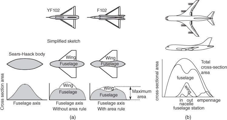
Figure 5.15 Area rule. (a) Transonic area rule. (b) Boeing transonic aircraft.
Whitcomb's finding was deployed on F102 Delta Dragger fighter aircraft (Figure 5.15a). The modified version with area ruling showed considerably reduced transonic drag. For current designs with wing‐body blending, it is less visible, but designers still study the volume distribution to make it as smooth as possible. Even the hump of a Boeing747 flying close to transonic speed helps with the area ruling. The following subsection considers wing (i.e. 3D body) aerodynamics.
In addition, the latest generation combat aircraft have leading edge root extension (LERX) (strakes), mostly above the engine intakes, where delineation between wings and body becomes difficult; normally taken at wing‐fuselage assembly joint line. These designs require developing fuselage mouldlines hugging the distributed internal contents, satisfying the CG location for a full flight envelope. Fuselage cross‐sections vary for the different types of combat aircraft configuration evolved by incorporating advanced technologies and mission requirement to encounter the potential adversaries with capabilities that can only be guessed. A BWB configuration like the B1 Spirit bomber aircraft design is seen as a flying wing, the fuselage merged and serves as part of the wing that also considers smooth changes in aircraft sectional area along its length.
5.10.3 Supersonic Effects
As a result of the presence of a shock wave, the flow physics of supersonic flow differs from subsonic flow. Nose cone of fuselage spearheads through air and develops a shock cone. Unlike thin aerofoils, the fuselage has conical angle of 2β (see Section 3.1) to displace air flow to produce a shock wave with and angle of shock β > μ.
5.11 Fuselage Pitching Moment
Fuselage pitching moment characterises contribute to the horizontal tail sizing (Chapter 6). Spindle‐shaped fuselage bodies are inherently unstable in the pitch plane.
Researchers and academics have proposed semi‐empirical relations, extracted from test data and backed‐up by theories, to obtain pitching moment coefficients, CM. The results can only give approximate values. Some of them are included in DATCOM, which progressed further to be unified and refined in an extensive manner for industry usage, serving many generations. DATCOM also shows the extent of discrepancies that can arise by comparing with test results. This evolved from Munk's original research [3] on dirigible like circular cross‐section bodies in inviscid flow. Such bodies do not produce lift, only pure moment. Therefore, the centre of pressure is considered in the limiting sense infinitely ahead of the body. Weight of the body is not an aerodynamic force, hence the position of CG has no role in developing an aerodynamic moment. He stated that the rate of change of moment developed with change in angle of attack is a function of body volume and the dynamic head ‘q’ (0.5ρV2) of the relative airflow over it as given next.
Later, Multhopp [4] refined with the generalisation to apply to non‐circular cross‐section spindle as in fuselage bodies. In real viscous flow fuselage lift generation is insignificantly small, hence it is neglected and hence the role of CG does not enter to have a lift contributed moment. Perkins and Hege [2] give the explanation of Multhopp's method. Nelson [5] and Pamadi [6] present DATCOM method [7] examples that can be used in academic courses.
Although the authors consider the DATCOM methods are complex and should be kept to minimum usage in undergraduate courses, two examples of the DATCOM method are presented in this section and in Section 6.7.3.
- Fuselage moment at zero incidence, CMf_0
Equation 5.6 gives the algebraic from of the relation to estimate fuselage moment coefficient, Cmf_0 (moment at zero angle of attack), for engineering computation.
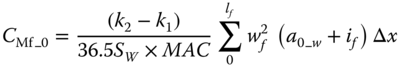
where
- SW is the wing reference area.
- MAC is the Mean Aerodynamic Chord of the wing
- Δx is the segment length
- (k2 − k1) is the correction factor for fuselage fineness ratio – use Figure 5.16a.
- wf is the average width of the fuselage cross‐sections
- a0_w wing zero lift line relative to fuselage reference line.
- if is the incidence of the fuselage camber line relative to fuselage reference line at the centre of the corresponding Δxi. Nose droop and aft‐sweep are each positive values.
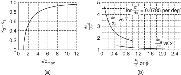
Figure 5.16 Fuselage moments factors. (a) Fuselage fineness correction factor. (b) Variation.
Figure 5.16a gives the values of (k2 − k1) and is reproduced from [7] (it is the same as given in NACA TM 1036, figure 2).
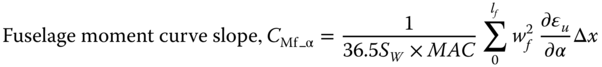
- Fuselage moment variation with angle of attack, CMf_α
Equation 5.7 shows the variation with angle of attack, α, given algebraic form for computational ease as shown in the worked‐out example that follows. The fuselage is inherently unstable, the front‐fuselage contributes much to the instability.
where ![]() is explained next. Other symbols are as before.
is explained next. Other symbols are as before.
Airflow ahead of the wing has upwash and downstream aft of the wing has downwash (Figure 5.17, Example 5.1). Local angle of attack, α, changes along the flow for the fuselage length. Therefore, each segment in the plan view has a different α. The term ![]() is the rate of upwash/downwash varying with α change, on account of contribution by the wing and the width of the fuselage contributes. The shaded fuselage section (darker shaded area by width, C) within the wing in the plan view does not contribute to Cmαf.
is the rate of upwash/downwash varying with α change, on account of contribution by the wing and the width of the fuselage contributes. The shaded fuselage section (darker shaded area by width, C) within the wing in the plan view does not contribute to Cmαf.
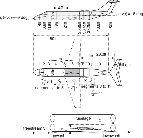
Figure 5.17 Fuselage moments estimation.
Front and with upwash deflected flow aft fuselage with downwash deflected flow ![]() values are computed differently.
values are computed differently.
For a considerably higher local α, the upwash ahead of wing contributes to the Cmαf more with ![]() > 1 than at the downstream, as can be seen directly from Figure 5.16b, Only one section next to the wing uses the top graph given in Figure 5.16b, all other ahead of it use the bottom graph: the strength attenuates to lowest value at the nose cone.
> 1 than at the downstream, as can be seen directly from Figure 5.16b, Only one section next to the wing uses the top graph given in Figure 5.16b, all other ahead of it use the bottom graph: the strength attenuates to lowest value at the nose cone.
Figure 5.16b for ![]() is taken from [7] (slightly modified). The top graph is used for one section just ahead for upwash values and all other sections use the bottom graph. These graphs are based on a wing AR = 8 with CLα_AR=8 = 4.5/rad (0.07 853/degree). For any other wing it has to adjusted by its CLα as follows.
is taken from [7] (slightly modified). The top graph is used for one section just ahead for upwash values and all other sections use the bottom graph. These graphs are based on a wing AR = 8 with CLα_AR=8 = 4.5/rad (0.07 853/degree). For any other wing it has to adjusted by its CLα as follows.

Downwash flow deflection gradually gets reduced as the downwash moves away from the wing to a value of 2w (not the downwash ‘w’ at the wing a.c.). Downwash deflection at the H‐tail = 2w and the deflected angle εdef (not the same ε to get the αeff but twice more).
Using Eq. (4.19), εdef = 2CL/(πAR).

![]() estimation for downwash flow deflection does not use the graphs. The following relation is used
estimation for downwash flow deflection does not use the graphs. The following relation is used
Together with Eqs. 5.6 and 5.7 the moment characteristics are obtained.
Example 5.1, given in a step‐by‐step manner, expands the procedure of computation in better details].
5.12 Nacelle Pod – Civil Aircraft
Nacelles are the structural housing for aircraft engine. The first commercial transport aircraft was the De Havilland Comet with four engines buried into the wing (Figure 5.18a). The configuration was found out to have high intake drag. The proven pod‐mounted nacelle, was there and the configuration with improved aerodynamic and structural features became the standard design (Figure 5.18b). Today, all multi‐engine civil aircraft nacelles are invariably externally pod‐mounted, either slung under or mounted over the wing or attached to the aft fuselage. The front part of the nacelle is the intake and the aft end is the nozzle for the hot engine exhaust flow, which should not impinge on any aircraft surface (hence fuselage mounted engines are positioned at the aft end).
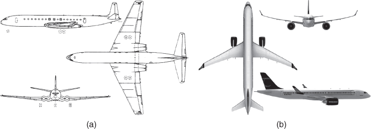
Figure 5.18 Aircraft nacelle. (a) De Havilland Comet. (b) Bombardier CS‐100. Credit Bombardier.
In a way, the external geometry of civil aircraft nacelle pod is a body of revolution with a near circular cross‐section varying along its length. Equation 5.1 is valid to obtain nacelle average diameter for a cross‐section. A pod casing may be seen as wrapped wing around an engine with aerofoil shaped casing sections facilitating a large diameter intake with short‐duct length for the air‐breathing engines. The crown‐cut section is thinner than the keel‐cut section as can be seen in Figure 12.5. The keel‐cut section is thicker to house accessories and its fuller lip contour helps to avoid separation at high angle of attack. In principle, it is desirable to have circular cross‐sectional areas for the intake throat area, but it may not always be possible, say for ground clearance. It may be noted that the Boeing737 nacelle has a flat keel line to gain some ground clearance. In this book, the intake areas would be considered circular.
Propeller driven aircraft generally operates at low subsonic speed. For the same power output, the air‐mass flow demand for turboprops is considerably lower as compared to turbofans. Their nacelle pod serves the same function to house the power plant but design consideration differs. They invariably have pilot intake but the internal airflow ducts are short and may have bends, still acting moderately as diffusers (Figure 5.19).
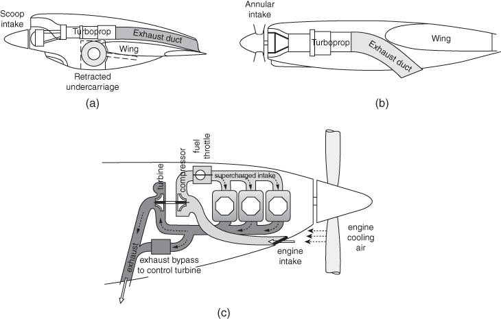
Figure 5.19 Sketch of a propeller driven engine nacelle pods. (a) Scoop intake TP nacelle. (b) annular intake TP nacelle. (c) Piston engine nacelle.
For subsonic turbofans, the intake acts as a diffuser with an acoustic lining to abate noise generation. The inhaled air‐mass flow demanded by an engine varies considerably: Intake design must also cater for flight at high incidence and yaw attitudes for the full flight envelope so that the flow distortion, separation and turbulence within the duct are at an acceptable level for engine to operate without compressor blade stall or engine flame out.
In principle, the external contour lines of good nacelle designs are not necessarily symmetrical to its vertical plane. But to keep cost down by maintaining commonality, some nacelle designs are made symmetrical to the vertical plane. This would allow manufacturing jigs to produce interchangeable nacelles between port and starboard sides and be able to minimise the essential difference at the finishing end.
5.12.1 Nacelle/Intake External Flow Aerodynamic Considerations
Nacelle pod is also like the fuselage 3D bodies of revolution as it has air flowing over it, but it differs as it also has internal airflow flowing through its intake duct facilitating air‐breathing into the engine. Nacelle aerodynamics need to be considered for both the external and internal flow characteristics. This section gives a brief introductory description of nacelle external aerodynamic considerations. Nacelle external flow aerodynamics have similar considerations as those discussed in Section 5.10.
In addition to housing the engine, the main purpose of the nacelle is to facilitate the internal airflow reaching the engine face (or the fan of gas turbines) with minimum distortion over a wide range of aircraft speeds and attitudes. Aircraft designers need to position the nacelle at an orientation to receive the incoming free stream tube into the intake duct with minimum distortion for the full flight envelope (see Section 5.8.1).
The nacelle aerodynamic design (external mouldline shaping and internal contouring) has progressed to a point of diminishing return on the efforts made and approaching to a generic shape. The characteristics length of nacelle is its length, lnac. It is long enough to have Re > Rcrit, hence separation can occur at the aft end of nacelle, its severity depends on its aft end closure shape. Separation contributes to drag increase. If required, vortex generators such as a few vanes are positioned at the critical positions. The entrainment effects of high energy engine exhaust flow helps to minimise separation of external flow over the aft end of fuselage. Nacelle pods are isolated bodies attached to aircraft with a pylon and have much lower length to diameter ratio (FR) compared to the fuselage.
Military aircraft with engines buried into the fuselage do not have nacelle pods; here, airflow to engine passes through a long intake duct. These are dealt with in better detail in Chapter 12.
5.12.2 Positioning Aircraft Nacelle Pod
In the vicinity of wing and/or fuselage, airflow past nacelle pod will be interfered with and that will give rise to interference drag. Positioning the nacelle pod with respect to the aircraft is an important design consideration.
The best position to place a nacelle pod is on the wing. The engine weight relieves some of the wing bending moment developed from wing lift force in flight. This also favours the aircraft CG to stay forward. However, low‐wing smaller aircraft do not have enough ground clearance for under‐slung nacelles, therefore they have to be mounted on the fuselage, always at the aft of it. Interestingly, Hondajet has defied the convention and positioned the nacelles over the wing. The authors believe that lessons from Hondajet's operational experiences will see more aircraft designs with over wing‐nacelle configuration. The considerations for a wing‐mounted nacelle (e.g. A320) and fuselage mounted nacelle (e.g. B727) differ as described in the following sub‐sections.
To minimise yaw moment at one‐engine inoperative situations, the engine thrust line should be as near to fuselage centre line as possible but at the same time not too close to cause high interference drag. As a compromise, typically, wing‐mounted nacelle pods are placed at about twice the maximum nacelle diameter ≈[±(2 × Dnac_max)] away from fuselage and aft‐fuselage nacelles placed at ≈[±(1.5 × Dnac_max)].
The closest an inboard engine should be kept to is at least 30° away from the nose wheel spray angle as shown in Figure 5.20 (B747 is a little widely spaced). It is found that the most inboard engines placed 30° from the nose wheel give the wing‐mounted nacelle position >[(2 × Dnac_max)].

Figure 5.20 Typical nacelle positions. (a) Nose wheel spray. (b) Position of nacelle with respect to the wing [8].
Aerodynamic, structural and CG locations influence the position of the nacelle with respect to the aircraft. This section discusses location of nacelle positions based on past experiences; those that are extracted from existing designs and those that are used during the conceptual design phase. Subsequently, in the next project design phase, the configuration is refined through CFD analyses.
5.12.3 Wing‐Mounted Nacelle Position
Structurally, outboard nacelle locations are desirable to reduce wing bending moments in flight but flutter requirements are complex and may show more inboard locations to be more favourable. The latter also favours directional control after engine failure. Finally, the lateral position of the engines affects ground clearance, an issue of special importance for large, four‐engine aircraft. Given next are some guidelines that may be used in classroom exercises. The following should be considered when positioning nacelles.
5.12.3.1 Summary – Lateral Nacelle Position
Table 5.5 Wing‐mounted lateral nacelle position
- To keep nacelle positioned >[±(2 × Dnac_max)].
- To stay clear of nose wheel spray during takeoff (Figure 5.20a).
- To keep exhaust flow not to impinge on flaps.
- To keep engine at a position to satisfy CG position with respect to the aircraft.
As a guide, aircraft designers will have to make the best compromises for where to position engine on wing. In the classroom, the following may be adopted to position wing‐mounted nacelles.
- two engines 0.3–0.32 of semi‐wing span from the aircraft centre line.
- three engines same as above – the third one at aircraft centre line.
- four engines inboard at 0.29–0.32 and outboard at 0.62–0.66 of the wing semi‐span.
Ideally, nacelles at either side should be identical to keep product commonality as a measure of cost reduction. However, they are not identical. A mirror image of slightly banana‐shaped nacelles gives the best flow alignment on account of being affected by the presence of the fuselage and wing.
5.12.3.2 Vertical Position
Typically, wing‐mounted nacelles are under slung below the wing supported by a pylon. The dominating design consideration is to minimise wing‐nacelle interference drag. All nacelles are hung well over (Figure 5.20b) and ahead of the wing to keep interference drag low, almost to zero. Most high bypass ratio turbofans have short‐duct nacelles (Section 12.7.1), the cold secondary fan exhaust flow ejects over the primary duct case. The nacelle pod should be forward enough with a short fan cowl exit plane that stays ahead of the wing leading edge. A typical gap between the nacelle and wing may be taken as ≈15% of the local wing chord length.
The current design practice is to keep the nacelle position as far ahead of the wing with an orientation to capture the three stream tube diffused through a short intake duct length, normal to the fan face. A forward nacelle position favours adjusting the aircraft CG position in the conceptual design stage. There is no quick answer for the degree of incidence (Figure 5.20b), which is design specific and varies for the type of installation. It depends on the engine position with respect to the wing, for example, how much inboard on the wing, the flexure of the wing during flight and so on. However, the considerations for fuselage mounted nacelles, as given next, offer some idea of wing‐mounted nacelle positions. Post conceptual design studies using CFD, wind tunnel and flight tests would fine‐tune nacelle geometry and positional geometry to production standards.
Three typical relative positions of the nacelle with respect to wing are shown in Figure 5.21 [1] in detail: the top wing represents a B747, the middle represents an A300 and the bottom wing represents a DC10.
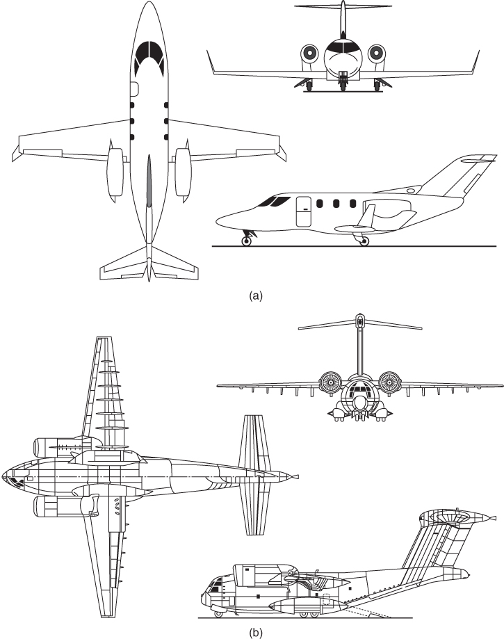
Figure 5.21 Typical position of nacelle with respect to the wing. (a) Hondajet. (b) BoeingYC‐12.
Other considerations are to keep adequate clearance for 15° roll during takeoff and landing (Figure 5.23).
5.12.3.3 Summary – Vertical Nacelle Position
- Short fan cowl exit plane stays ahead of the wing leading edge.
- Take the gap between nacelle and the wing as ≈15% of the local wing chord length.
- Keep adequate clearance for 15° roll during takeoff and landing.
5.12.3.4 Over‐Wing Nacelle
One of the earliest over‐wing podded jet engine nacelles was the experimental VWF‐Fokker 614 and now is the Hondajet. Over‐wing nacelle design (Figure 5.21) has not caught up yet. The authors believe that over‐wing nacelle design shows good potential. During the 1970s, the BoeingYC‐14 experimental STOL aircraft was built. Later, the Antanov 72 and 74, using a similar design concept, were produced.
5.12.4 Fuselage‐Mounted Nacelle Position
The wing‐mounted nacelle position, as discussed in Section 5.12.3, also offers some ideas for considerations of fuselage mounted nacelle positions (Figures 5.22). Fuselage mounted nacelle contours have similarity in design, but because there are no constraints of the wing, the interference drag is lower and can be brought closer to the fuselage, thus clearing the thicker boundary growth at the aft fuselage. A gap of roughly at least half the nacelle diameter may be left between fuselage and the nacelle. The vertical position is where it offers the least pitching moment developed by engine thrust about the CG for the whole aircraft, taking into account of contribution by the H‐tail. The position can be anywhere close to the fuselage centreline to high up on fuselage.
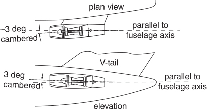
Figure 5.22 Fuselage mounted nacelle position.
With an aft engine installations, the nacelles must be placed to be free of interference from wing wakes. The DC‐9 was investigated thoroughly for wing and spoiler wakes and the effects of yaw angles, which might cause the fuselage boundary layer to be ingested. Here, efficiency is not the concern because little flight time is spent yawed, with spoilers deflected or at a high angle of attack. However, the engine cannot tolerate excessive fan face flow distortion.
An aft fuselage mounted nacelle has many special problems. The pylons should be as short as possible to minimise drag but long enough to avoid aerodynamic interference between fuselage, pylon and nacelle. To minimise this interference without excessive pylon length, the nacelle cowl should be designed to minimise local velocities on the inboard size of the nacelle. On a DC‐9 a wind tunnel study compared cambered and symmetrical, long and short cowls and found the short banana shaped cambered cowl to be best and lightest in weight. The nacelles are cambered in both the plan and elevation views to compensate for the angle of attack at the nacelle (Figure 5.22).
5.12.4.1 Summary – Fuselage Mounted Nacelle Position
Aircraft designers will have to make the best compromises for where to position an engine on a wing. For a classroom exercise, the following may be considered when positioning a nacelle on a fuselage.
- To stay clear of wing wake.
- To keep nacelle positioned >[±(1.5 × Dnac_max)], clear of fuselage boundary layer ingestion.
- To ensure exhaust flow does not interfere with empennage.
- To keep the engine forward enough to satisfy CG position with respect to the aircraft.
- Attitude with respect to the fuselage centre line may have a 3° offset as shown in Figure 5.22.
5.12.5 Trijet Centre Engine
A trijet aircraft configuration has its odd engine at the centreline placed at the aft of the aircraft fuselage (Figure 5.23). The dominant choices are to have an S‐duct (B727) with the engine at the tail cone of the fuselage or straight through a duct (DC10) clear above the aft fuselage with a V‐tail on its top. This large nacelle pod over the fuselage also serves as part of a fin stabiliser for the aircraft.
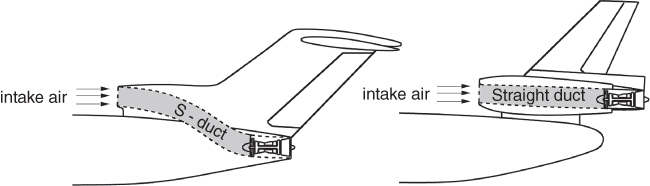
Figure 5.23 Trijet centre engine.
The S‐duct configuration is lighter in construction but has lower recovery factor (RF – Section 13.2.1) with intake duct loss. The straight duct configuration is heavier but has a high RF in the order of a conventional nacelle pod. A tradeoff study (DOC comparison) is required to make the choice.
The S‐bend has a lower engine location and uses the engine exhaust to replace part of the fuselage boat‐tail (saves drag). It has more inlet loss, a distortion risk and higher inlet drag from the S‐duct bend. The straight‐through inlet with the engine mounted on the fin has an ideal aerodynamic inlet free of distortion, but does have a small inlet loss due to the length of the inlet and an increase in fin structural weight to support the engine.
5.12.6 Some Structural Considerations
Structurally, outboard nacelle locations are desirable to reduce wing bending moments in flight but flutter requirements are complex and may show more inboard locations to be more favourable. The latter also favours directional control after engine failure. Finally, the lateral position of the engines affects ground clearance, an issue of special importance for large, four‐engine aircraft.
Nacelle pod clearance from ground must ensure avoidance of debris ingestion. Also, crashworthiness of the pod in case of nose wheel collapse has to be catered for as shown in Figure 5.24.
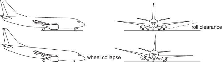
Figure 5.24 Nacelle pod clearance from ground.
Source: Reproduced with permission from Cambridge University Press.
Although rare, high heavy turbine discs at high rpm have disintegrated under high stress of centrifugal force operating at elevated temperature. The fragments have enough energy to cut through the fuselage shell causing catastrophic accidents. To contain fragments, the inner cowls around the rotor are reinforced by Kevlar, a material is also used as tank armour plates.
Another influence of wing‐mounted nacelles is the effect on flaps. The high temperature, high ‘q’ exhaust impinging on the flap increases flap loads and weight and may require a titanium structure (more expensive). The impingement also increases drag, a significant factor in takeoff climb performance after engine failure. Eliminating the flap behind the engine reduces CLmax.
In principle, the external contour lines of good nacelle designs are not necessarily symmetrical to its vertical plane. But to keep cost down by maintaining commonality, most nacelle designs are made symmetrical to the vertical plane. This would allow manufacturing jigs to produce interchangeable nacelles between port and starboard sides and be able to minimise the essential difference at the finishing end. The nacelle aerodynamic design (external mould‐line shaping and internal contouring) has progressed to a point of diminishing return on the efforts made and approaching to a generic shape.
Post‐conceptual design studies using CFD, wind tunnel and flight tests would fine‐tune the nacelle geometry and its positional geometry to production standards.
5.13 Exhaust Nozzles – Civil Aircraft
Civil aircraft nozzles are conical in which a thrust reverser (TR) is integrated. Small turbofan aircraft may not need a TR but aircraft of the RJ size and above use a TR. Inclusion of a TR may slightly elongate nozzle length – this will be ignored in this book.
In general, nozzle exit area is sized as a perfectly expanded nozzle (pe = p∞) at long range cruise (LRC) conditions. At higher engine ratings, pe > p∞. The exit nozzle of a long duct turbofan does not run choked at cruise ratings. At takeoff ratings, the back pressure is high at lower altitude, therefore a long duct turbofan could escape from running choked (low pressure secondary flow mixes within the exhaust duct. The exhaust nozzle runs in a favourable pressure gradient, hence its shaping is relatively simple to establish geometrical dimensions. However, it is not a simple engineering task to suppress noise level and withstand elevated temperature.
Nozzle exit plane is at the end of engine. Its length from the turbine exit plane is about 0.8–1.5 of the fan face diameter. Nozzle exit area diameter may be taken coarsely as half to three‐quarters of intake throat diameter in this study.
Each possibility entails compromises of weight, inlet loss, inlet distortion, drag, reverser effectiveness and maintenance accessibility.
5.13.1 Civil Aircraft Thrust Reverser (TR)
TRs are not required by the regulatory authorities (Federal Aviation Administration , FAA/Civil Aviation Authority, CAA). They are expensive components, heavy and only applied on ground, yet their impact on aircraft operation is significant on account of having additional safety through better control, reduced time to stop and so on, especially at aborted takeoffs and other related emergencies. Airlines want to have TRs even at the cost of increased DOC.
Broadly speaking, there are two types of TRs: (i) those operating on a mixed fan and core flow and (ii) those operating on fan flow only. Their choice depends on BPR, nacelle location and customer specification.
The first type operating on the total flow (both fan and core) is shown the top of Figure 5.25. There are two types: (i) sliding port aft door type when the doors slides to the aft end as it opens up to deflect the exhaust flow and (ii) fixed pivot type when the doors rotates to position to deflect the exhaust flow.
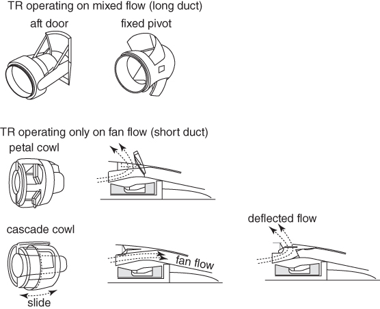
Figure 5.25 Type of thrust reversers.
The second type of TR operates on the fan flow only. There are two types: (i) the petal cowl type – its mechanism is the middle of Figure 5.25 – and (ii) the cascade cowl type shown at the bottom of Figure 5.25. There are two cascade types: the conventional type and the natural blockage type. Bombardier CRJ700/900 aircraft use their own patented cascade TR of the natural blockage type. The external cowls translate back blocking the fan flow when it escapes through fixed cascades that reverse the flow. This is an attractive design with low parts count, scalable, easier to maintain and offers relatively higher retarding energy. The petal type operating on fan flow is suitable to short‐duct nacelles as shown in the figure. The petal doors open on a hinge to block the secondary flow of the fan when it deflects to develop reverse thrust.
TRs are applied below 150 kts and are retracted back at around 50 kts when wheel brakes are effective. The choice for the type would depend on designer's comprise from the available technology at his/her disposal. Aircraft designers must ensure TR efflux is well controlled – there should be no adverse impingement of on aircraft surface nor there be re‐ingestion in the engine. Figure 5.26 gives a typical satisfactory TR efflux pattern.
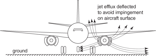
Figure 5.26 TR efflux pattern (from [9]).
MILITARY AIRCRAFT
5.14 Fuselage Geometry – Military Aircraft
Unlike the transport aircraft fuselage geometries, military have varied cross‐sections as shown in Figure 5.27. The military geometries are generated based on mission depended design specifications stemming from the technology level adopted. Military mission roles are listed in Section 5.2. Choices of military aircraft fuselages are also given subsequently in Chapter 7. The following geometrical definitions of civil aircraft design are extensively used in this book.
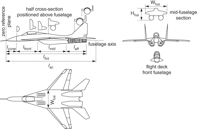
Figure 5.27 MIG29 type of combat aircraft (extracted from various sources – not to scale).
Source: Reproduced with permission from Cambridge University Press.
A combat aircraft with a blunt engine exit plane does not have a pointed aft fuselage closure. A single engine configuration may have boat‐tail like aft end (Figure 5.4a) closure but twin side‐by‐side engine configurations do not require boat tailing (Figure 5.4b). With a shorter wheel base and longer wheel strut there is little or no fuselage upsweep for the takeoff rotation clearance.
The mission requirements for combat aircraft are different from civil aircraft requirements (Section 1.9.1). In a way, there is no payload except to carry ammunitions for internal mounted gun as consumables. The avionics pods, drop fuel tanks and expendable armaments are carried externally (except for bombers). Combat aircraft have their engine installed at the aft end of fuselage, facilitating the hot exhaust to flow out. These factors act as driver to have combat aircraft with varied cross‐sections along the fuselage as shown Figure 5.27.
5.14.1 Fuselage Axis/Zero‐Reference Plane – Military Aircraft
Fuselage axis is a line parallel to the centreline of the constant cross‐section part of the fuselage barrel. It typically passes through the farthest point of the nose cone, facilitating the start of reference planes normal to it. The fuselage axis may or may not be parallel to the ground. The principal inertia axis of the aircraft can be close to the fuselage axis. In general, the zero‐reference plane is at the nose cone, but designers can choose any station for their convenience, within or outside of the fuselage. This book considers the fuselage zero‐reference plane to be at the nose cone, as shown in Figure 5.27.
5.14.2 Fuselage Length, lfus
This is along the fuselage axis, measuring the length of the fuselage from the tip of the nose cone to engine exit plane. Fuselages are further sectioned at the joints of the fabricated subassembly sections built in their dedicated jigs. As the manufacturing philosophies may differ, the fuselage sections subassemblies differ from design to design. Figure 5.27 gives a typical example.
5.14.3 Fuselage Nose Cone, lcone
The pointed nose cone is the front closure is the aerodynamic requirement for supersonic flight and also serves as the housing for the radar, which is mounted at the front of the fuselage front section, lfront, bulkhead.
5.14.4 Front‐Fuselage Length, lfront
Following the nose cone is the front‐fuselage sub‐assembly with the length, lfront. This is the dedicated section to house the flight deck (crew station) for the crew, mostly single seated but can be dual (as required for the role), either in tandem or side‐by‐side arrangement. A canopy with streamlined windscreen mould lines covers pilot CFD.
5.14.5 Mid‐Fuselage Length, lmid
The mid‐fuselage length, lmid, of the subassembly follows the lfront up to the engine face carrying the intake ducts, cables, linkages and, depending on the design the fuel tanks, filling up the section cavity.
5.14.6 Aft‐Fuselage Closure Length, laft
Aft‐fuselage closure length, laft, is the last subassembly section following the lmid housing the power plants. As mentioned earlier, combat aircraft with a blunt engine exhaust plane have no transport aircraft like pointed closure. Typically, this does not require an upsweep angle.
5.14.7 Fuselage Height, Hfus
Fuselage height, Hfus, is the maximum distance of the fuselage from its underside (not from the ground) to the top in the vertical plane (Figure 5.27). Combat aircraft fuselage cross‐section varies along the fuselage length, hence each cross‐section along the fuselage length has to be considered separately.
5.14.8 Fuselage Width, Wfus
Fuselage width, Wfus, is the widest part of the fuselage in the horizontal plane. Combat aircraft fuselage cross‐section varies along the fuselage length, hence each cross‐section along the fuselage length has to be considered separately.
5.14.9 Fuselage Cross‐Sectional Area, Afus
Combat aircraft cross‐section area along fuselage stations is an important parameter to establish fuselage volume distribution required to estimate aircraft supersonic drag (Section 11.18). Being non‐circular, the concept of average or equivalent cross‐section diameter is not relevant. The term effective diameter, Deff, as given in Eq. 5.2, exists for a non‐circular cross‐section as a reference value. It is not used in this book.
Because of complex and varying fuselage cross‐sections along the length, there is difficulty in interpreting military aircraft FR. The definition of FR with average or equivalent diameter serves little purpose, except as a reference number.
5.15 Pilot Cockpit/Flight Deck – Military Aircraft
The ‘crew station’ for the operator, in most design a single pilot but in some designs there may be second crew as weapons operator to alleviate pilot work‐load. The operator can have a side‐by‐side or tandem seating arrangement. This is the space allocated in the front‐fuselage to accommodate pilot/crew. A canopy seals the space not only as protection but also facilitates environmental control. Current canopy design has moved away from raised flat‐shield design to bubble canopy offering generous vision polar. The older practice of raised canopy are now applied to bomber like bigger aircraft.
A single‐piece bird‐proof polycarbonate bubble canopy give the pilot 360° all‐round unobstructed vision, greatly improved vision over the side and to the rear. The upward vision is unrestricted, the side vision typically is 40° look‐down and forward vision is typically 15° looking down over the nose cone.
Flight deck design is an integral part of fuselage layout as shown in Figure 5.28. A raised bubble canopy offers unrestricted view for the pilot in the upper hemisphere. The nose cone cavity houses the forward‐looking radar and other black boxes.

Figure 5.28 Flight deck (cockpit) layout – military aircraft.
Source: Reproduced with permission from Cambridge University Press.
The reclining angle pilot seat is also moved away from the rather upright older angle of around 12° to tilting backward at 30°. A more inclined position of pilot seating reduces the height of the carotid artery to the brain, giving an additional margin on high‐g manoeuvres to avoid causing black out.
5.15.1 Flight Deck Height, Hfd
This is the internal cabin height from the flight deck floorboard to canopy top, as shown in Figure 5.28.
5.15.2 Flight Deck Width, Wfd
Flight deck width, Wfd (Figure 5.28), should be generous for accommodate the 99% percentile crew size. The Wfd should be more than 38 in. width. Fuselage width at the canopy interface should be adequate for ejection seat egress with its width close to 38 in. (trainer aircraft = 0.35–0.37 in.). Details of ejection process is given in Chapter 17.
5.15.3 Egress
See Section 22.8.1.
5.16 Engine Installation – Military Aircraft
Combat aircraft have engines integral with the fuselage buried inside. Therefore, pods do not feature unless there is a requirement for more than two engines on a large aircraft.
Figure 5.29 shows a turbofan installed onto a supersonic combat aircraft. Power plants are placed at the aft end, hence they have a longer duct acting as a diffuser incurring higher flow energy loss. The external contour of the engine housing is integral to fuselage mouldlines. More details are given in Section 5.8.2; internal flow through the intake duct is discussed in Chapter 9. Military aircraft internal contours design of the intake and exit nozzle are the obligation of aircraft designers done in consultation with the engine manufacturer.
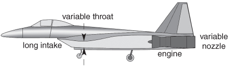
Figure 5.29 Installed engine in a combat aircraft.
5.16.1 Military Aircraft Intake
While military aircraft do not have pods, their intake geometries have many configuration possibilities. Chart 5.1 gives the dominant types of military aircraft intake configurations: all have an engine buried in the fuselage.

Figures 5.30 and 5.31 give examples of the intake configurations given in the Chart 5.1. Earlier designs had an intake at the nose of aircraft for both subsonic (e.g. F86 with pitot intake) and supersonic (e.g. MIG21 with a movable centre body) operations. A centre body is required for aircraft speed capability above Mach 1.8, otherwise it can be pitot intake. The intake ducts were long and had bends to go below the pilot and then up again to the engine face, incurring flow energy loss resulting in low RF.
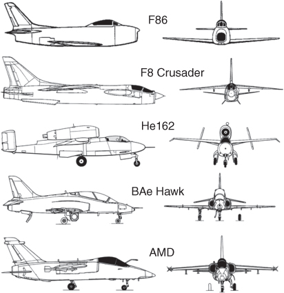
Figure 5.30 Subsonic combat aircraft intakes (various sources).

Figure 5.31 Supersonic combat aircraft intakes (various sources).
Later, with side intakes, bifurcated to both sides of fuselage considerably improved the RF by shortening the duct length. The loss from the bends on account of bifurcation of the intake duct is minimised through careful contouring, nowadays with CFD analyses. Other possibilities with a short intake duct is to have chin intake (e.g. F16) under the fuselage or intake over the fuselage (e.g. F107). Shorter intake ducts have the benefits of weight saving.
Intake design must also cater for flight at high incidence and yaw attitudes for the full flight envelope, so the flow distortion, separation, turbulence within the duct are at acceptable levels for engine to operate with compressor blade stall or engine flame outs.
Unlike the aircraft front intake, the side intakes are subjected to a breath of air flowing past the front section of the fuselage with the consequence of having boundary layer adhered to the fuselage surface in a favourable pressure gradient of the increasing fuselage cross‐section. Ingestion of this boundary layer through the intake will degrade engine performance. This problem is overcome by installing a splitter plate (Figure 5.32) acting as diverter to bleed the boundary layer to spill out from both sides the splitter/diverter plate. An adjustable ramp (F5) on splitter plate acts as shock diffuser. Front‐fuselage mounted gun is to be positioned to avoid ingestion of hot gas efflux from firing rounds.
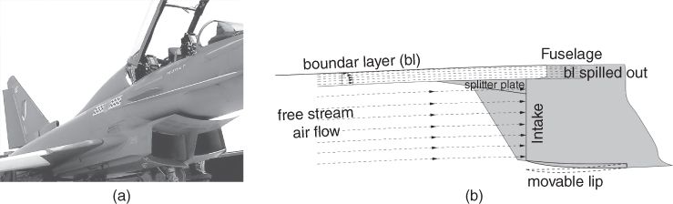
Figure 5.32 Splitter plate for boundary layer bleed (Eurofighter Typhoon). (a) Typhoon intake. (b) Splitter plate.
Subsequently, further advancement have been achieved by using Diverterless Supersonic Inlet (DSI) is a type of jet engine air intake used by some modern combat aircraft to control air flow into their engines. It consists of a ‘bump’ (Figure 5.33) and a forward‐swept inlet cowl, which work together to divert boundary layer airflow away from the aircraft's engine. This eliminates the need for a splitter plate, while compressing the air to slow it down from supersonic to subsonic speeds. The DSI can be used to replace conventional methods of controlling supersonic and boundary‐layer airflow. This is a good example of using CFD to design DSI intake. It is practically impossible to find the shape of the bump for the DSI without using CFD.
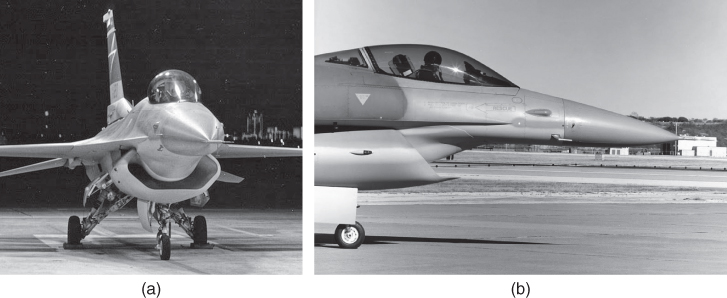
Figure 5.33 F16 modified with diverterless supersonic intake (DSI) for flight testing. (a) F16 Diverterless supersonic intake. (b) DSI side view. (
The DSI bump functions as a compression surface and creates a pressure distribution that prevents the majority of the boundary layer air from entering the inlet at speeds up to Mach 2. There is no need for variable geometry supersonic intake for shock diffusion. There are considerable advantages with the DSI, as follows. Diverterless inlets lighten the aircraft weight.
- Eliminates complex and heavy mechanical systems. There is a low part count.
- Eliminates drag producing splitter plate through the boundary layer bleed passage.
- No moving parts; for example, travelling centre body for shock diffusion.
Powerful gas turbine air intake at maximum power creates a strong suction vortex as shown in Figure 5.34a with ground water sucked in at the high‐wing mounted military transport aircraft. This is capable of ingesting solid debris damaging the engine that may lead in to engine failures. Foreign object debris (FOD) ingestion by engine is a real harmful issue and must be prevented. Airfields for civil operation keeps the metalled cleaned several times a day, also as and when required as observed from frequent inspections. Boeing737 pods are low slung too close to the ground, hence they have vortex dissipaters to reduce the airflow suction at the bottom part of the intake to reduce the chances of FOD ingestion. Personnel in front of operating engines is strictly forbidden – fatalities have occurred. Some turbofans do not have stationary fan guide vanes in the front of the engine.
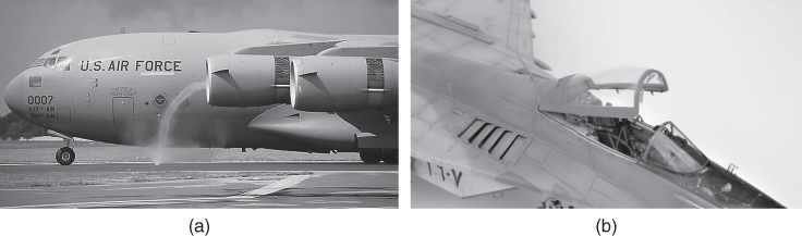
Figure 5.34 Intake vortex suction and protection. (a) Ground water suck. (b) MIG 29 auxiliary air intake.
High powered supersonic turbofan intakes in military aircraft are positioned much lower and may need to be operated from a rougher macadam airfield when gravel ingestion is certain to occur. As an adaptation to rough‐field operations, some designs, for example, the MIG 29 (Figure 5.34b), have the provision to close the front main air inlet, supported by properly sized louvre like the auxiliary air inlet on the upper side of the wing strakes under which the main inlet is positioned. The pilot operated auxiliary louvre intake is engaged during in field performance during takeoff and landing only. One of the other possibilities to prevent FOD ingestion is to have mesh screens in the main intake. For an S‐shaped duct, the side intake has a spring loaded flapped door suitably positioned at the end of the S‐bend so that the harmful heavier FOD failing to negotiate the bend hits a flap door to be thrown outside. S‐duct design incurs flow energy loss and is not desirable.
Last but not the least in nacelle/intake design considerations, is retaining engine accessibility for MRO activities.
References
- 1. Jane's All the World's Aircraft Manual (yearly publication). Jane's Information Group.
- 2. Perkins, C.D. and Hege, R.E. (1988). Airplane Performance, Stability and Control. New York: Wiley.
- 3. Munk, M. M., The Aerodynamic Forces on Airship Hull, NACA TR 184, 1924.
- 4. Multhopp, H. (1942). Aerodynamics of Fuselage, NACA TM 1036.
- 5. Nelson, R.C. (1989). Flight Stability and Automatic Control. New York: McGraw‐Hill.
- 6. Pamadi, B.N. (2015). Performance, Stability, Dynamics and Control of Airplanes, 3e. USA: AIAA, Reston, VI.
- 7. Fink, R. D. (1978). USAF Stability and Control, DATCOM. Report Number AFWAL‐TR‐83‐3048, Flight Dynamic Laboratory, Wright‐Patterson Air force Base, Ohio, April.
- 8. Cohen, R.H. and Saravamutto, H.I.H. (2001). Gas Turbine Theory, 5e. Harlow: Pearson.
- 9. Gunston, W. (2006). The Development of Jet and Turbine Aeroengines, 4e. Patrick Stephens Ltd.