
Chapter 2. Conversion and Reactor Sizing
Be more concerned with your character than with your reputation, because character is what you really are while reputation is merely what others think you are.
—John Wooden, coach, UCLA Bruins
2.1 Definition of Conversion
In defining conversion, we choose one of the reactants as the basis of calculation and then relate the other species involved in the reaction to this basis. In virtually all instances we must choose the limiting reactant as the basis of calculation. We develop the stoichiometric relationships and design equations by considering the general reaction
![]()
The uppercase letters represent chemical species, and the lowercase letters represent stoichiometric coefficients. We shall choose species A as our limiting reactant and, thus, our basis of calculation. The limiting reactant is the reactant that will be consumed first after the reactants have been mixed. Next, we divide the reaction expression through by the stoichiometric coefficient of species A, in order to arrange the reaction expression in the form
![]()
to put every quantity on a “per mole of A” basis, our limiting reactant.
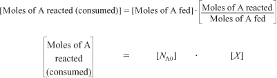
Now we ask such questions as “How can we quantify how far a reaction [e.g., Equation (2-2)] proceeds to the right?” or “How many moles of C are formed for every mole of A consumed?” A convenient way to answer these questions is to define a parameter called conversion. The conversion XA is the number of moles of A that have reacted per mole of A fed to the system:
![]()
Because we are defining conversion with respect to our basis of calculation [A in Equation (2-2)], we eliminate the subscript A for the sake of brevity and let X ≡ XA. For irreversible reactions, the maximum conversion is 1.0, i.e., complete conversion. For reversible reactions, the maximum conversion is the equilibrium conversion Xe (i.e., Xmax = Xe). We will take a closer look at equilibrium conversion in Chapter 4.
2.2 Batch Reactor Design Equations
In most batch reactors, the longer a reactant stays in the reactor, the more the reactant is converted to product until either equilibrium is reached or the reactant is exhausted. Consequently, in batch systems the conversion X is a function of the time the reactants spend in the reactor. If NA0 is the number of moles of A initially present in the reactor (i.e., t = 0), then the total number of moles of A that have reacted (i.e., have been consumed) after a time t is [NA0 X].
Now, the number of moles of A that remain in the reactor after a time t, NA, can be expressed in terms of NA0 and X:
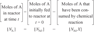
The number of moles of A in the reactor after a conversion X has been achieved is
![]()
When no spatial variations in reaction rate exist, the mole balance on species A for a batch system is given by the following equation [cf. Equation (1-5)]:
![]()
This equation is valid whether or not the reactor volume is constant. In the general reaction, Equation (2-2), reactant A is disappearing; therefore, we multiply both sides of Equation (2-5) by –1 to obtain the mole balance for the batch reactor in the form
![]()
The rate of disappearance of A, –rA, in this reaction might be given by a rate law similar to Equation (1-2), such as –rA = kCACB.
For batch reactors, we are interested in determining how long to leave the reactants in the reactor to achieve a certain conversion X. To determine this length of time, we write the mole balance, Equation (2-5), in terms of conversion by differentiating Equation (2-4) with respect to time, remembering that NA0 is the number of moles of A initially present in the reactor and is therefore a constant with respect to time.
Combining the above with Equation (2-5) yields
![]()
For a batch reactor, the design equation in differential form is
![]()
We call Equation (2-6) the differential form of the design equation for a batch reactor because we have written the mole balance in terms of conversion. The differential forms of the batch reactor mole balances, Equations (2-5) and (2-6), are often used in the interpretation of reaction rate data (Chapter 7) and for reactors with heat effects (Chapters 11–13), respectively. Batch reactors are frequently used in industry for both gas-phase and liquid-phase reactions. The laboratory bomb calorimeter reactor is widely used for obtaining reaction rate data. Liquid-phase reactions are frequently carried out in batch reactors when small-scale production is desired or operating difficulties rule out the use of continuous flow systems.
To determine the time to achieve a specified conversion X, we first separate the variables in Equation (2-6) as follows.
![]()
This equation is now integrated with the limits that the reaction begins at time equal zero where there is no conversion initially (when t = 0, X = 0) and ends at time t when a conversion X is achieved (i.e., when t = t, then X = X). Carrying out the integration, we obtain the time t necessary to achieve a conversion X in a batch reactor

The longer the reactants are left in the reactor, the greater will be the conversion. Equation (2-6) is the differential form of the design equation, and Equation (2-7) is the integral form of the design equation for a batch reactor.

2.3 Design Equations for Flow Reactors
For a batch reactor, we saw that conversion increases with time spent in the reactor. For continuous-flow systems, this time usually increases with increasing reactor volume, e.g., the bigger/longer the reactor, the more time it will take the reactants to flow completely through the reactor and thus, the more time to react. Consequently, the conversion X is a function of reactor volume V. If FA0 is the molar flow rate of species A fed to a system operated at steady state, the molar rate at which species A is reacting within the entire system will be FA0X.

The molar feed rate of A to the system minus the rate of reaction of A within the system equals the molar flow rate of A leaving the system FA. The preceding sentence can be expressed mathematically as

Rearranging gives
![]()
The entering molar flow rate of species A, FA0 (mol/s), is just the product of the entering concentration, CA0 (mol/dm3), and the entering volumetric flow rate, υ0 (dm3/s).
![]()
For liquid systems, CA0 is commonly given in terms of molarity, for example,
CA0 = 2 mol/dm3
For gas systems, CA0 can be calculated from the entering mole fraction, yA0, the temperature, T0, and pressure, P0, using the ideal gas law or some other gas law. For an ideal gas (see Appendix B):
![]()
Now that we have a relationship [Equation (2-8)] between the molar flow rate and conversion, it is possible to express the design equations (i.e., mole balances) in terms of conversion for the flow reactors examined in Chapter 1.