
5.5.4 Analytical Solution for Reaction with Pressure Drop
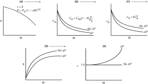
Let’s reason out how pressure drop affects our CRE algorithm. Figure 5-8 shows qualitatively the effects of pressure drop on reactor design. Starting with Figure 5-8(a) we see how the Ergun equation predicts the pressure decrease down the packed-bed reactor. The subsequent figures, (b) through (e), show this effect of pressure drop on concentration, reaction rate, conversion, and volumetric flow rate, respectively. Each of these figures compares the respective profiles when there is a pressure drop with those profiles for no pressure drop. We see that when there is pressure drop in the reactor, the reactant concentrations, and thus reaction rate for reaction (for reaction orders greater than 0 order), will always be smaller than the case with no pressure drop. As a result of this smaller reaction rate, the conversion will be less with pressure drop than without pressure drop.
Figure 5-8. Effect of pressure drop on P (a), CA (b), –rA (c), X (d), and υ (e).
Second-Order Reaction in a PBR
Now that we have expressed pressure as a function of catalyst weight [Equation (5-33) for ε = 0], we can return to the second-order isothermal reaction,
![]()
to relate conversion and catalyst weight. Recall our mole balance, rate law, and stoichiometry.
- Mole Balance:
- Rate Law:

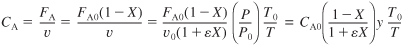
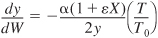
- Stoichiometry. Gas-phase isothermal reaction (T = T0) with ε = 0. From Equation (5-23), υ = υ0/y
Using Equation (5-33) to substitute for y in terms of the catalyst weight, we obtain
CA = CA0(1 – X)(1 – αW)1/2
- Combining:

- Separating Variables:
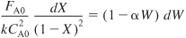
Integrating with limits X = 0 when W = 0 and substituting for FA0 = CA0υ0 yields

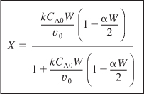
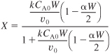
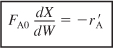
6.A Solving for conversion gives
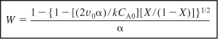
6.B Solving for the catalyst weight, we have
Example 5-5. Effect of Pressure Drop on the Conversion Profile
Reconsider the packed-bed reactor in Example 5-4 for the case where a second-order reaction
2A → B + C
is taking place in 20 meters of a 1½-inch schedule 40 pipe packed with catalyst. The flow and packed-bed conditions in the example remain the same except that they are converted to SI units; that is, P0 = 10 atm = 1013 kPa, and
Entering volumetric flow rate: υ0 = 7.15 m3/h (252 ft3/h)
Catalyst pellet size: Dp = 0.006 m(ca. ¼-inch)
Solid catalyst density: ρc = 1923 kg/m3 (120 lbm/ft3)
Cross-sectional area of 1½-inch schedule 40 pipe: AC = 0.0013 m2
Pressure drop parameter: β0 = 25.8 kPa/m
Reactor length: L = 20 m
We will change the particle size to learn its effect on the conversion profile. However, we will assume that the specific reaction rate, k, is unaffected by particle size, an assumption we know from Chapter DVD12 on the DVD-ROM is valid only for small particles.
a. First, calculate the conversion in the absence of pressure drop.
b. Next, calculate the conversion accounting for pressure drop.
The entering concentration of A is 0.1 kmol/m3 and the specific reaction rate is
![]()
Using Equation (5-38)
For the bulk catalyst density,
ρb = ρc(1 – φ) = (1923)(1 – 0.45) = 1058 kg/m3
The weight of catalyst in the 20 m of 1½-inch schedule 40 pipe is

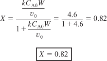
a. First calculate the conversion for ΔP = 0 (i.e., α = 0)
E5-5.1
b. Next, we calculate the conversion with pressure drop. Recalling Equation (5-29) and substituting the bulk density ρb = (1 – φ) ρc = 1058 kg/m3
E5-5.2
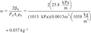
then
E5-5.3
![]()
E5-5.4
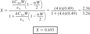
We see the predicted conversion dropped from 82.2% to 69.3% because of pressure drop. It would be not only embarrassing but also an economic disaster if we had neglected pressure drop and the actual conversion had turned out to be significantly smaller.
c. Robert the Worrier wonders: What if we increase the catalyst size by a factor of 2?

Let’s help Robert out! We see from Equation (E5-4.4) that the second term in the Ergun equation is dominant; that is,
E5-5.5
![]()
Therefore, from Equation (5-25)
![]()
we have
E5-5.6
![]()
We see for the conditions given by Equation (E5-5.6) that the pressure drop parameter varies inversely with the particle diameter
![]()
We will learn more about Robert the Worrier on DVD-ROM Chapter 11.
and thus
![]()
For Case 2, we double the particle diameter DP2 = 2DP1
E5-5.7
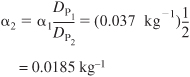
Substituting this new value of α in Equation (E5-5.4)
We see the conversion is greater for the larger particle because ΔP is smaller.
It is important to be able to carry out an engineering analysis using case 1 and case 2 and then taking ratios to estimate the effect of changing parameters on conversion and reactor operation.
Analysis: Because there is no change in the net number of moles during this isothermal gas phase reaction occurring in a PBR, one can obtain an analytical solution to our CRE algorithm instead of using the Polymath software. Now let’s look at what we could expect changing the particle diameter of the catalyst pellets.
By increasing the particle diameter, we decrease the pressure drop parameter and thus increase the reaction rate and the conversion. However, Chapter 10 and DVD-ROM Chapter 12 explain that when interparticle diffusion effects are important in the catalyst pellet, this increase in conversion with increasing particle size will not always be the case. For larger particles, it takes a longer time for a given number of reactant and product molecules to diffuse in and out of the catalyst particle where they undergo reaction (see Figure 10-5). Consequently, the specific reaction rate decreases with increasing particle size k ~ 1/DP [see DVD-ROM Chapter 12, Equation (12-35)], which in turn decreases the conversion (see Figure 10-9). At small particle diameters, the rate constant, k, is large, and at its maximum value, but the pressure drop is also large, resulting in a low rate of reaction. At large particle diameters, the pressure drop is small, but so is the rate constant, k, and the rate of reaction, resulting in low conversion. Thus, we see a low conversion at both large and small particle diameters with an optimum in between. This optimum is shown in Figure E5-5.1.
Figure E5-5.1. Finding the optimum particle diameter.

The variation ![]() is discussed in detail in DVD-ROM Chapter 12. Also, see Chapter 5 Summary Notes.
is discussed in detail in DVD-ROM Chapter 12. Also, see Chapter 5 Summary Notes.

If pressure drop is to be minimized, why not pack the catalyst into a larger diameter tube to decrease the superficial velocity, G, thereby reducing ΔP? There are two reasons for not increasing the tube diameter: (1) There is an increased chance the gas could channel and bypass most of the catalyst, resulting in little conversion; (2) the ratio of the heat-transfer surface area to reactor volume (catalyst weight) will be decreased, thereby making heat transfer more difficult for highly exothermic and endothermic reactions.
We now proceed in Example 5-6 to combine pressure drop with reaction in a packed bed when we have volume change with reaction and therefore cannot obtain an analytical solution.6
Example 5-6. Calculating X in a Reactor with Pressure Drop
Approximately 8.5 billion pounds of ethylene oxide were produced in the United States. The 2010 selling price was $0.53 a pound, amounting to a commercial value of $4.0 billion. Over 60% of the ethylene oxide produced is used to make ethylene glycol. The major end uses of ethylene oxide are antifreeze (30%), polyester (30%), surfactants (10%), and solvents (5%). We want to calculate the catalyst weight necessary to achieve 60% conversion when ethylene oxide is to be made by the vapor-phase catalytic oxidation of ethylene with air.
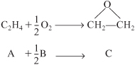
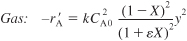
Ethylene and oxygen are fed in stoichiometric proportions to a packed-bed reactor operated isothermally at 260°C. Ethylene is fed at a rate of 136.21 mol/s at a pressure of 10 atm (1013 kPa). It is proposed to use 10 banks of 1½-inch-diameter schedule 40 tubes packed with catalyst with 100 tubes per bank. Consequently, the molar flow rate to each tube is to be 0.1362 mol/s. The properties of the reacting fluid are to be considered identical to those of air at this temperature and pressure. The density of the 1/4-inch-catalyst particles is 1925 kg/m3, the bed void fraction is 0.45, and the gas density is 16 kg/m3. The rate law is
![]()
with
![]()
The catalyst density, particle size, gas density, void fraction, pipe cross sectional area, entering pressure, and superficial velocity are the same as in Example E5-4. Consequently we are in luck. Why are we in luck? Because we don’t have to calculate the pressure drop parameters β0 and α because they are the same as those calculated in Example 5-4 and we will use these values, i.e., β0 = 25.8 atm/m and α = 0.0367 kg–1 in this example.
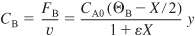
- Differential Mole Balance:

- Rate Law:


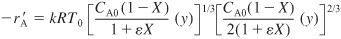
- Stoichiometry. Gas-phase, isothermal υ = υ0(1 + εX)(P0/P):

For stoichiometric feed


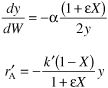
For isothermal operation, Equation (5-30) becomes

- Combining the rate law and concentrations:
We can evaluate the combine step either
- Analytically
- Graphically
- Numerically, or
- Using software
Factoring
 and recalling PA0 = CA0 RT0, we can simplify Equation (E5-6.7) to
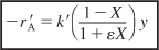
where

- Parameter evaluation per tube (i.e., divide feed rates by 1000):

where

As noted in the problem statement, β0 = 25.8 kPa/m and α = 0.0367kg–1
- Summary. Combining Equation (E5-6.1) and (E5-6.8) and summarizing


We will guess the final catalyst weight to achieve 60% conversion to be 27 kg.
Wf = 27 kg
We have the boundary conditions W = 0, X = 0, y = 1.0, and Wf = 27kg. Here we are guessing an upper limit of the integration to be 27 kg, with the expectation that 60% conversion will be achieved within this catalyst weight. If 60% conversion is not achieved, we will guess a higher weight and redo the calculation.
A large number of ordinary differential equation solver software packages (i.e., ODE solvers), which are extremely user friendly, have become available. We shall use Polymath7 to solve the examples in this book. With Polymath, one simply enters Equations (E5-6.9) and (E5-6.10) and the corresponding parameter values [Equations (5-6.11) through (5-6.14)] into the computer with the boundary conditions and they are solved and displayed as shown in Figures E5-6.1 and E5-6.2. Equations (E5-6.9) and (E5-6.10) are entered as differential equations and the parameter values are set using explicit equations. The rate law may be entered as an explicit equation in order to generate a plot of reaction rate as it changes down the length of the reactor, using Polymath’s graphing function. The DVD-ROM contains all of the MATLAB and Polymath solution programs used to solve the example problems, as well as an example using AspenTech. Consequently, one can load the Polymath program directly from the DVD-ROM, which has programmed Equations (E5-6.9) through (E5-6.14), and run the program for different parameter values.
It is also interesting to learn what happens to the volumetric flow rate along the length of the reactor. Recalling Equation (4-23),
![]()
We let f be the ratio of the volumetric flow rate, υ, to the entering volumetric flow rate, υ0, at any point down the reactor. For isothermal operation Equation (4-23) becomes
![]()
The Polymath program and output are shown in Figures E5-6.1 and E5-6.2.
Table E5-6.1. Polymath Program
(Information on how to obtain and load the Polymath software can be found in Appendix E. Tutorials can be found on the DVD-ROM home page under Living Examples, Polymath.)
ODE REPORT (STIFF)
Figure E5-6.1. Polymath program.
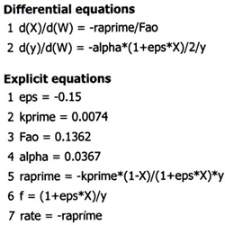
Figure E5-6.2. Numerical output.


![]()
For all Living Example Problems, Polymath and MATLAB can be loaded from the DVD-ROM (see the Introduction).
Figure E5-6.3(a) shows X, y (i.e., y = P/P0), and f down the length of the reactor. We see that both the conversion and the volumetric flow increase along the length of the reactor, while the pressure decreases. Figure 5-6.3(b) shows how the rate of reaction, ![]() , decreases as we move down the reactor. For gas-phase reactions with orders greater than zero, the decrease in pressure will cause the reaction rate to be less than in the case of no pressure drop.
, decreases as we move down the reactor. For gas-phase reactions with orders greater than zero, the decrease in pressure will cause the reaction rate to be less than in the case of no pressure drop.
Figure E5-6.3. Output in graphical form from Polymath.

From either the conversion profile (shown in Figure E5-6.3) or the Polymath table of results (not shown in the text, but available on the DVD-ROM), we find 60% conversion is achieved with 20 kg catalyst in each tube.
We note from Figure E5-6.3. that the catalyst weight necessary to raise the conversion the last 1% from 65% to 66% (0.9 kg) is 8.5 times more than that required to raise the conversion 1% at the reactor’s entrance. Also, during the last 5% increase in conversion, the pressure decreases from 3.8 atm to 2.3 atm.
This catalyst weight of 20 kg/tube corresponds to a pressure drop of approximately 5 atm. If we had erroneously neglected pressure drop, the catalyst weight would have been found by integrating equation (E5-6.9) with y = 1 to give
![]()

Neglecting pressure drop results in poor design (here 53% vs. 60% conversion)
Analysis: If we had used this 16 kg per tube catalyst weight in our reactor, we would have had insufficient catalyst to achieve the desired conversion. For this 16 kg catalyst weight, Figure E5-6.3(a) shows that for the case of pressure drop, only 53% conversion would have been achieved and this would have been embarrassing. In arriving at this job-saving conclusion we applied the CRE algorithm to a gas phase reactions with a change in the total number of moles carried out in a PBR. The only small change from the previous example is that we had to use the ODE solver Polymath to combine and solve all the steps to obtain the profiles of the reaction rate (–rA), conversion (X), pressure ratio (P/P0) and volumetric flow rate ratio (f) as a function of catalyst weight down the length of the PBR.
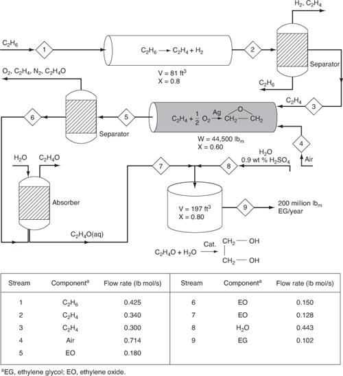
5.6 Synthesizing the Design of a Chemical Plant

Careful study of the various reactions, reactors, and molar flows of the reactants and products used in the example problems in this chapter reveals that they can be arranged to form a chemical plant to produce 200 million pounds of ethylene glycol from a feedstock of 402 million pounds per year of ethane. The flowsheet for the arrangement of the reactors, together with the molar flow rates, is shown in Figure 5-9. Here 0.425 lb mol/s of ethane is fed to 100 tubular plug-flow reactors connected in parallel; the total volume is 81 ft3 to produce 0.34 lb mol/s of ethylene (see Example 5-3). The reaction mixture is then fed to a separation unit where 0.04 lb mol/s of ethylene is lost in the separation process in the ethane and hydrogen streams that exit the separator. This process provides a molar flow rate of ethylene of 0.3 lb mol/s, which enters the packed-bed catalytic reactor together with 0.15 lb mol/s of O2 and 0.564 lb mol/s of N2. There are 0.18 lb mol/s of ethylene oxide (see Example 5-6) produced in the 1000 pipes arranged in parallel and packed with silver-coated catalyst pellets. There is 60% conversion achieved in each pipe and the total catalyst weight in all the pipes is 44,500 lbm. The effluent stream is passed to a separator where 0.03 lb mol/s of ethylene oxide is lost. The ethylene oxide stream is then contacted with water in a gas absorber to produce a 1-lb mol/ft3 solution of ethylene oxide in water. In the absorption process, 0.022 lb mol/s of ethylene oxide is lost. The ethylene oxide solution is fed to a 197-ft3 CSTR, together with a stream of 0.9 wt % H2SO4 solution, to produce ethylene glycol at a rate of 0.102 lb mol/s (see Example 5-2). This rate is equivalent to approximately 200 million pounds of ethylene glycol per year.
Figure 5-9. Production of ethylene glycol.
The profit from a chemical plant will be the difference between income from sales and the cost to produce the chemicals. An approximate formula might be
Profit =Value of products – Cost of reactants – Operating costs – Separation costs
The operating costs include such costs as energy, labor, overhead, and depreciation of equipment. You will learn more about these costs in your senior design course. While most, if not all, of the streams from the separators could be recycled, let’s consider what the profit might be if the streams were to go unrecovered. Also, let’s conservatively estimate the operating and other expenses to be $12 million per year and calculate the profit. Your design instructor might give you a better number. The 2006 prices of ethane, sulfuric acid, and ethylene glycol are $0.17, $0.15, and $0.69 per pound, respectively. See www.chemweek.com for current prices.
For an ethane feed of 400 million pounds per year and a production rate of 200 million pounds of ethylene glycol per year. The profit is shown in Table 5-4.
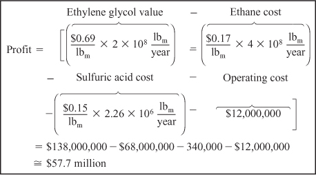
You will learn more economics of chemical processing in your senior design class.
Using $58 million a year as a rough estimate of the profit, you can now make different approximations about the conversion, separations, recycle streams, and operating costs to learn how they affect the profit.
Closure. This chapter presents the heart of chemical reaction engineering for isothermal reactors. After completing this chapter, the reader should be able to apply the algorithm building blocks

to any of the reactors discussed in this chapter: batch reactor, CSTR, PFR, and PBR. The reader should be able to account for pressure drop and describe the effects of the system variables such as catalyst particle size on the PBR conversion and explain why there is an optimum in the conversion when the catalyst particle size is varied. The reader should be able to use conversion to solve chemical reaction engineering problems. Finally, after completing this chapter, the reader should be able to work the California Professional Engineers’ Exam Problems in approximately 30 minutes [cf. P5-11B through P5-15B] and to diagnose and troubleshoot malfunctioning reactors [cf. P5-8B].
Summary
- Solution algorithm
a. Mole Balances (CSTR, PFR, PBR):
S5-1

b. Rate law: For example,
S5-2

c. Stoichiometry:
- Liquid phase: υ = υ0
S5-3
- Gas phase:
S5-4

S5-5
For a PBR
S5-6

Variable density with ε = 0 or
 and isothermal operation:
S5-7
d. Combining the rate law and stoichiometry for isothermal operation in a PBR

e. Solution techniques:
- Numerical integration—Simpson’s rule
- Table of integrals
- Software packages
a. Polymath
An ODE solver (e.g., Polymath) will combine all the equations for you.
- Liquid phase: υ = υ0
ODE Solver Algorithm
When using an ordinary differential equation (ODE) solver such as Polymath or MATLAB, it is usually easier to leave the mole balances, rate laws, and concentrations as separate equations, rather than combining them into a single equation as we did to obtain an analytical solution. Writing the equations separately leaves it to the computer to combine them and produce a solution. The formulations for a packed-bed reactor with pressure drop are given below for an elementary reversible reaction carried out isothermally.

Polymath will combine and solve the above equations and then allow you to plot the variables (e.g., y, –rA, CA) as a function of W or each other. The Polymath solution to the above equation is given on the DVD-ROM in the Chapter 5 Summary Notes.
DVD-ROM Material

• Learning Resources
- Summary Notes
- Web Modules
A. Wetlands
B. Membrane Reactors
C. Reactive Distillation
- Interactive Computer Games
A. Murder Mystery

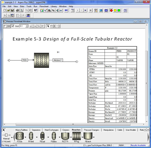
B. AspenTech solution to Problem 5-3.
C. Reactor Lab Modules
The following reactor Lab Modules on the DVD-ROM have been developed by Professor Richard Herz in the Chemical Engineering Department at the University of California, San Diego. They are copyrighted by UCSD and Professor Hertz and are used here with their permission.

- Solved Problems
A. A sinister-looking gentlemen is interested in producing methyl perchlorate in a batch reactor. The reactor has a strange and unsettling rate law. [ECRE, 2nd Ed. P4-28]
B. Solution to California Professional Engineers’ Exam Problem
C. Ten Types of Home Problems: 20 Solved Problems
- Analogy of CRE Algorithms to a Menu in a Fine French Restaurant
- Algorithm for Gas Phase Reaction
• Living Example Problems
- Example 5-6 Calculating Conversion in a Reactor with Pressure Drop
- AspenTech solution to Example Problem 5-3.
• Professional Reference Shelf
R5.1.
Spherical Packed-Bed Reactors
When small catalyst pellets are required, the pressure drop can be significant. One type of reactor that minimizes pressure drop and is also inexpensive to build is the spherical reactor, shown here. In this reactor, called an ultraformer, dehydrogenation reactions such as
![]()
are carried out.
Recycle Reactors
Recycle reactors are used (1) when conversion of unwanted (toxic) products is required and they are recycled to extinction, (2) the reaction is autocatalytic or (3) it is necessary to maintain isothermal operation. To design recycle reactors, one simply follows the procedure developed in this chapter and then adds a little additional bookkeeping.
Questions and Problems
The subscript to each of the problem numbers indicates the level of difficulty: A, least difficult; D, most difficult.
![]()

In each of the following questions and problems, rather than just drawing a box around your answer, write a sentence or two describing how you solved the problem, the assumptions you made, the reasonableness of your answer, what you learned, and any other facts that you want to include. You may wish to refer to W. Strunk and E. B. White, The Elements of Style, 4th ed. (New York: Macmillan, 2000) and Joseph M. Williams, Style: Ten Lessons in Clarity & Grace, 6th ed. (Glenview, Ill.: Scott, Foresman, 1999) to enhance the quality of your sentences.
Read through all the problems at the end of this chapter. Make up and solve an original problem based on the material in this chapter. (a) Use real data and reactions from the literature. (b) Make up a reaction and data. (c) Use an example from everyday life (e.g., making toast or cooking spaghetti). In preparing your original problem, first list the principles you want to get across and why the problem is important. Ask yourself how your example will be different from those in the text or lecture. Other things for you to consider when choosing a problem are relevance, interest, impact of the solution, time required to obtain a solution, and degree of difficulty. Look through some of the journals for data or to get some ideas for industrially important reactions or for novel applications of reaction engineering principles (the environment, food processing, etc.). At the end of the problem and solution, describe the creative process used to generate the idea for the problem. (d) Write a question based on the material in this chapter that requires critical thinking. Explain why your question requires critical thinking. [Hint: See Preface, Section B.2] (e) Listen to the audios on the DVD-ROM ![]() Lecture Notes, pick one, and describe how you might explain it differently.
Lecture Notes, pick one, and describe how you might explain it differently.
What if... you were asked to explore the example problems in this chapter to learn the effects of varying the different parameters? This sensitivity analysis can be carried out by either downloading the examples from the Web or by loading the programs from the DVD-ROM supplied with the text. For each of the example problems you investigate, write a paragraph describing your findings.
a. Example 5-1. What would be the error in k if the batch reactor were only 80% filled with the same concentrations of reactants, instead of being completely filled as in the example? What generalizations can you draw from this example?
b. Example 5-2. (1) What conversion would be achieved if three 800-gallon CSTRs were placed in series? In parallel with the feed equally divided? (2) What are the advantages and disadvantages of adding this third reactor? (3) Show that for n equal sized CSTRs, Vi, placed in parallel with equal feed to each, FAi0 = FA0/n, that conversion achieved in any one of the reactors will be identical to what would be achieved if the reactor were fed in one stream, FA0 = nFAi0, to one large reactor of volume V = nVi.
c. Example 5-3. How would your reactor volume and number of reactors change if you only needed 50% conversion to produce the 200 million pounds per year required? What generalizations can you draw from this example?
d. Example 5-4. How would the pressure drop and pressure drop parameters, α and β0 change if the particle diameter were reduced by 25%? Plot α as a function of φ, keeping constant the other parameters in the example. What generalizations can you draw from this example?
e. Example 5-5. What would be the reactor volume for X = 0.8 if the pressure were increased by a factor of 10, assuming everything else remains the same? Plot and analyze –rA as a function of V. What generalizations can you draw from this example?
f. Example 5-6. Load the Living Example Problem 5-6 from the DVD-ROM. How much would the catalyst weight change if the pressure was increased by a factor of 5 and the particle size decreased by a factor of 5 (recall α is also a function of P0)? Use plots and figures to describe what you find.
g. AspenTech Example 5-3. (1) Using FA0 = 0.425 lbm mol/s, run the AspenTech simulation at 1000 K and at 1200 K and compare with the specified temperature a 1100 K. (2) Explore what a small change in activation energy can make in your results by changing E from 82 kcal/mol to 74 kcal/mol and then to 90 kcal/mol and compare your results with the base case of 82 kcal/mol. (3) Double both the flow rate of A and the pressure and describe what you find.
h. How would your profit/numbers change in Table 5-4 if you used the following 2010 prices? Ethylene glycol $0.54/kg, ethylene $0.76/kg, ethylene oxide $1.17/kg, ethane $0.31/kg, sulfuric acid $0.10/kg (98 wgt %), and propylene glycol $1.70/kg. What pops out at you?
i. Learn a New Dance. View the YouTube video (www.youtube.com) made by the chemical reaction engineering students at the University of Alabama, entitled CSTR to the tune of YMCA. Type in “chemicalreactor” to narrow your search. You can also access it directly from a link in Chapter 5 Summary Notes on the Web site (www.umich.edu/~essen), scroll down until you find the YouTube “CSTR.”
j. Load reactor lab on to your computer and call up D1 Isothermal Reactors. Detailed instructions with screen shots are given in Chapter 4 Summary Notes. (1) For L1 Nth Order Reactions, vary the parameters n, E, T for a batch, CSTR, and PFR. Write a paragraph discussing the trends (e.g., first order versus second order) and describe what you find. (2) Next choose the “Quiz” on the membrane at the top of the screen, and find the reaction order (3) and turn in your performance number.
Performance number: __________________
Load the Interactive Computer Games (ICG) from the DVD-ROM. Run the games and then record your performance number, which indicates your mastery of the material. Your instructor has the key to decode your performance number.
a. ICG—Mystery Theater—A real “who done it?,” see Pulp and Paper, 25 (January 1993) and also Pulp and Paper, 9 (July 1993). The outcome of the murder trial is summarized in the December 1995 issue of Paper-maker, page 12. You will use fundamental chemical engineering from Sections 5.1 to 5.3 to identify the victim and the murderer.
If it takes 11 minutes to cook spaghetti in Ann Arbor, Michigan, and 14 minutes in Boulder, Colorado, how long would it take in Cuzco, Peru? Discuss ways to make the spaghetti more tasty. If you prefer to make a creative spaghetti dinner for family or friends rather than answering this question, that’s OK, too; you’ll get full credit—but only if you turn in your recipe and bring your instructor a taste. (Ans. t = 21 min)
Troubleshooting
a. A liquid-phase isomerization ![]() is carried out in a 1000-gal CSTR that has a single impeller located halfway down the reactor. The liquid enters at the top of the reactor and exits at the bottom. The reaction is second order. Experimental data taken in a batch reactor predicted the CSTR conversion should be 50%. However, the conversion measured in the actual CSTR was 57%. Suggest reasons for the discrepancy and suggest something that would give closer agreement between the predicted and measured conversions. Back your suggestions with calculations. P.S. It was raining that day.
is carried out in a 1000-gal CSTR that has a single impeller located halfway down the reactor. The liquid enters at the top of the reactor and exits at the bottom. The reaction is second order. Experimental data taken in a batch reactor predicted the CSTR conversion should be 50%. However, the conversion measured in the actual CSTR was 57%. Suggest reasons for the discrepancy and suggest something that would give closer agreement between the predicted and measured conversions. Back your suggestions with calculations. P.S. It was raining that day.

b. The first-order gas-phase isomerization reaction
![]()
is to be carried out in a tubular reactor. For a feed of pure A of 5 dm3/min, the expected conversion in a PFR is 63.2%. However, when the reactor was put in operation, the conversion was only 61.8%. We should note that the straight tubular reactor would not fit in the available space. One engineer suggested that the reactor be cut in half and the two reactors be put side by side with equal feed to each. However, the chief engineer overrode this suggestion, saying the tubular reactor had to be one piece, so he bent the reactor in a W-like shape, i.e., ![]() . The one bend was not a good one. Brainstorm and make a list of things that could cause this off-design specification. Choose the most logical explanation/model, and carry out a calculation to show quantitatively that with your model the conversion is 61.8%. [An Ans: 30% of the total]
. The one bend was not a good one. Brainstorm and make a list of things that could cause this off-design specification. Choose the most logical explanation/model, and carry out a calculation to show quantitatively that with your model the conversion is 61.8%. [An Ans: 30% of the total]

c. The liquid-phase reaction
![]()
was carried out in a CSTR. For an entering concentration of 2 mol/dm3, the conversion was 40%. For the same reactor volume and entering conditions as the CSTR, the expected PFR conversion is 48.6%. However, the PFR conversion was, amazingly, 52.6% exactly. Brainstorm reasons for the disparity. Quantitatively show how these conversions came about (i.e., the expected conversion and the actual conversion).
d. The gas-phase reaction
![]()
Multiple Choice. In each case you will need to explain the reason you chose the answer you did.
a. An irreversible, liquid-phase, second-order reaction, A → Product(s), proceeds to 50% conversion in a PFR operating isothermally, isobarically, and at steady state. What conversion would be obtained if the PFR operated at half the original pressure (with all else unchanged)?
- > 50%
- < 50%
- 50%
b. An irreversible, gas-phase, second order reaction, A → Product(s), proceeds to 50% conversion in a PFR operating isothermally, isobarically, and at steady state. What conversion would be obtained if the PFR operated at half the original pressure (with all else unchanged)?
- > 50%
- < 50%
- 50%
- insufficient information to answer definitively
c. The rate constant for an irreversible, heterogeneously catalyzed, gas-phase, second-order reaction, A → Product(s), was determined to be 0.234 from experimental data in a packed-bed reactor. The person analyzing the experimental data failed to include the large pressure drop in the reactor in his analysis. If the pressure drop were properly accounted for, the rate constant would be
- >0.234
- <0.234
- 0.234
- insufficient information to answer definitively
Multiple Choice. In each of the cases below, (a) through (e), you will need to explain why you chose the answer you did.
The elementary isomerization exothermic reaction
![]()
is carried out isothermally at 400K in a PBR in which pressure drop plays a role, with α = 0.001 kg–1. Currently 50% conversion is achieved. The equilibrium constant at this temperature is 3.0.
a. For a fixed mass flow rate ![]() . If the reactor diameter is increased by a factor of 4, the conversion will
. If the reactor diameter is increased by a factor of 4, the conversion will
- X > 0.5
- X < 0.5
- X = 0.5
b. For a fixed mass flow rate ![]() . The equilibrium conversion is
. The equilibrium conversion is
- Xe = 0.5
- Xe = 0.667
- Xe = 0.75
- insufficient information to tell
c. For a fixed mass flow rate ![]() , if the reactor diameter is increased by a factor of 2, the equilibrium conversion Xe will
, if the reactor diameter is increased by a factor of 2, the equilibrium conversion Xe will
- increase
- decrease
- remain the same
- insufficient information to tell
d. For a fixed mass flow rate ![]() , if the particle size is increased, the equilibrium conversion will
, if the particle size is increased, the equilibrium conversion will
- increase
- decrease
- remain the same
- insufficient information to tell
e. For a fixed mass flow rate ![]() , if the particle size is increased, the conversion will
, if the particle size is increased, the conversion will
- increase
- decrease
- remain the same
- insufficient information to tell
The liquid-phase reaction
![]()

follows an elementary rate law and is carried out isothermally in a flow system. The concentrations of the A and B feed streams are 2 M before mixing. The volumetric flow rate of each stream is 5 dm3/min, and the entering temperature is 300 K. The streams are mixed immediately before entering. Two reactors are available. One is a gray 200.0-dm3 CSTR that can be heated to 77°C or cooled to 0°C, and the other is a white 800.0-dm3 PFR operated at 300 K that cannot be heated or cooled but can be painted red or black. Note that k = 0.07 dm3/mol·min at 300 K and E = 20 kcal/mol.
a. Which reactor and what conditions do you recommend? Explain the reason for your choice (e.g., color, cost, space available, weather conditions). Back up your reasoning with the appropriate calculations.
b. How long would it take to achieve 90% conversion in a 200-dm3 batch reactor with CA0 CB0 = 1 M after mixing at a temperature of 77°C?
c. What would your answer to part (b) be if the reactor were cooled to 0°C? (Ans. 2.5 days)
d. What conversion would be obtained if the CSTR and PFR were operated at 300 K and connected in series? In parallel with 5 mol/min to each?
e. Keeping Table 4-3 in mind, what batch reactor volume would be necessary to process the same amount of species A per day as the flow reactors, while achieving 90% conversion? Referring to Table 1-1, estimate the cost of the batch reactor.
f. Write a couple of sentences describing what you learned from the problem and what you believe to be the point of the problem.
The gas phase reaction
A → B + C
follows an elementary rate law and is to be carried out first in a PFR and then in a separate experiment in a CSTR. When Pure A is fed to a 10 dm3 PFR at 300K and a volumetric flow rate of 5 dm3/s, the conversion is 80%. When a mixture of 50% A and 50% inert (I) is fed to a 10 dm3 CSTR at 320K and a volumetric flow rate of 5 dm3/s the conversion is also 80%. What is the activation energy in cal/mol?
The gas phase irreversible first-order reaction
A → 3B
is carried out first in a PFR, where the feed is equal molar in A and inerts. The conversion under these circumstances is 50%. The exit from the PFR is fed to a CSTR of the same volume and carried out under identical conditions (i.e., temperature, pressure) in a CSTR of the same volume. What is the conversion exiting the CSTR?
The dehydration butanol of alumina is carried out over a silica alumina catalyst at 680 K.
![]()
The rate law is

with k = 0.054 mol/gcat•h•atm and KBu = 0.32 atm–1. Pure butanol enters a thin tubed packed-bed reactor at a molar flow rate 50 kmol/hr and a pressure of 10 atm (1013•kPa).
a. What PBR catalyst weight is necessary to achieve 80% conversion in the absence of pressure drop? Plot and analyze X, y, f (i.e., (υ/υ0)) and reaction rate, ![]() , as a function of catalyst weight.
, as a function of catalyst weight.
b. What “fluidized CSTR” catalyst weight is necessary to achieve 80% conversion?
c. Repeat (a) when there is pressure drop, with the pressure drop parameter α = 0.0006 kg–1. Do you observe a maximum in the rate of reaction, and if so, why? What catalyst weight is necessary to achieve 70% conversion? Compare this weight with that for no pressure drop to achieve the same conversion.
d. What generalizations can you make about this problem?
The elementary gas-phase reaction
(CH3)3COOC(CH3)3 → C2H6 + 2CH3COCH3
is carried out isothermally in a flow reactor with no pressure drop. The specific reaction rate at 50°C is 10–4 min–1 (from pericosity data) and the activation energy is 85 kJ/mol. Pure di-tert-butyl peroxide enters the reactor at 10 atm and 127°C and a molar flow rate of 2.5 mol/min. Calculate the reactor volume and space time to achieve 90% conversion in:
a. a PFR [Ans.: 967 dm3]
b. a CSTR [Ans.: 4700 dm3]
c. Pressure drop. Plot and analyze X, y, as a function of the PFR volume when α = 0.001 dm–3. What are X and y at V = 500 dm3?
d. Apply one or more of the six ideas in Table P-3, page xiii to this problem.
e. If this reaction is to be carried out isothermally at 127°C and an initial pressure of 10 atm in a constant-volume batch mode with 90% conversion, what reactor size and cost would be required to process (2.5 mol/min × 60 min/h × 24 h/day) 3600 mol of di-tert-butyl peroxide per day? [Hint: Recall Table 4-1.]
A reversible liquid-phase isomerization ![]() is carried out isothermally in a 1000-gal CSTR. The reaction is second order in both the forward and reverse directions. The liquid enters at the top of the reactor and exits at the bottom. Experimental data taken in a batch reactor shows the CSTR conversion to be 40%. The reaction is reversible with KC = 3.0 at 300 K, and
is carried out isothermally in a 1000-gal CSTR. The reaction is second order in both the forward and reverse directions. The liquid enters at the top of the reactor and exits at the bottom. Experimental data taken in a batch reactor shows the CSTR conversion to be 40%. The reaction is reversible with KC = 3.0 at 300 K, and ![]() cal/mol. Assuming that the batch data taken at 300 K are accurate and that E = 15,000 cal/mol, what CSTR temperature do you recommend to obtain maximum conversion? [Hint: Read Appendix C and assume ΔCP = 0 in the appendix Equation (C-9)]:
cal/mol. Assuming that the batch data taken at 300 K are accurate and that E = 15,000 cal/mol, what CSTR temperature do you recommend to obtain maximum conversion? [Hint: Read Appendix C and assume ΔCP = 0 in the appendix Equation (C-9)]:
![]()
Use Polymath to make a plot of X versus T. Does it go through a maximum? If so, explain why.
The liquid phase hydrolysis of acetic anhydride to form acetic acid is
(CH3CO)2O + H2O → 2CH3COOH
to be carried out in a 1 liter CSTR and in a 0.311 liter PFR. The volumetric flow rate to in each case is 3.3 × 10⁻³ dm3/s. The reaction follows an elementary rate law with a specific reaction rate of 1.95 × 10⁴ dm3/mol · s. The concentrations of acetic anhydride and water in the feed to the reactors are 1M and 51.2M respectively. Find the conversion in (a) the CSTR and (b), the PFR.
Try to work the California Professional Engineers’ Exam problems in 30 minutes, which is the time normally allotted.
The gaseous reaction ![]() has a unimolecular reaction rate constant of 0.0015 min–1 at 80°F. This reaction is to be carried out in parallel tubes 10 ft long and 1 in. inside diameter, under a pressure of 132 psig at 260°F. A production rate of 1000 lb/h of B is required. Assuming an activation energy of 25,000 cal/mol, how many tubes are needed if the conversion of A is to be 90%? Assume perfect gas laws. A and B each have molecular weights of 58. [From California Professional Engineers’ Exam.]
has a unimolecular reaction rate constant of 0.0015 min–1 at 80°F. This reaction is to be carried out in parallel tubes 10 ft long and 1 in. inside diameter, under a pressure of 132 psig at 260°F. A production rate of 1000 lb/h of B is required. Assuming an activation energy of 25,000 cal/mol, how many tubes are needed if the conversion of A is to be 90%? Assume perfect gas laws. A and B each have molecular weights of 58. [From California Professional Engineers’ Exam.]
![]()
a. The irreversible elementary reaction 2![]() takes place in the gas phase in an isothermal tubular (plug-flow) reactor. Reactant A and a diluent C are fed in equimolar ratio, and conversion of A is 80%. If the molar feed rate of A is cut in half, what is the conversion of A assuming that the feed rate of C is left unchanged? Assume ideal behavior and that the reactor temperature remains unchanged. What was the point of this problem? [From California Professional Engineers’ Exam.]
takes place in the gas phase in an isothermal tubular (plug-flow) reactor. Reactant A and a diluent C are fed in equimolar ratio, and conversion of A is 80%. If the molar feed rate of A is cut in half, what is the conversion of A assuming that the feed rate of C is left unchanged? Assume ideal behavior and that the reactor temperature remains unchanged. What was the point of this problem? [From California Professional Engineers’ Exam.]
![]()
Compound A undergoes a reversible isomerization reaction, ![]() , over a supported metal catalyst. Under pertinent conditions, A and B are liquid, miscible, and of nearly identical density; the equilibrium constant for the reaction (in concentration units) is 5.8. In a fixed-bed isothermal flow reactor in which backmixing is negligible (i.e., plug flow), a feed of pure A undergoes a net conversion to B of 55%. The reaction is elementary. If a second, identical flow reactor at the same temperature is placed downstream from the first, what overall conversion of A would you expect if:
, over a supported metal catalyst. Under pertinent conditions, A and B are liquid, miscible, and of nearly identical density; the equilibrium constant for the reaction (in concentration units) is 5.8. In a fixed-bed isothermal flow reactor in which backmixing is negligible (i.e., plug flow), a feed of pure A undergoes a net conversion to B of 55%. The reaction is elementary. If a second, identical flow reactor at the same temperature is placed downstream from the first, what overall conversion of A would you expect if:
a. The reactors are directly connected in series? [Ans.: X = 0.74.]
b. The products from the first reactor are separated by appropriate processing and only the unconverted A is fed to the second reactor?
![]()
A total of 2500 gal/h of metaxylene is being isomerized to a mixture of orthoxylene, metaxylene, and paraxylene in a reactor containing 1000 ft3 of catalyst. The reaction is being carried out at 750°F and 300 psig. Under these conditions, 37% of the metaxylene fed to the reactor is isomerized. At a flow rate of 1667 gal/h, 50% of the metaxylene is isomerized at the same temperature and pressure. Energy changes are negligible.
![]()
It is now proposed that a second plant be built to process 5500 gal/h of metaxylene at the same temperature and pressure as described earlier. What size reactor (i.e., what volume of catalyst) is required if conversion in the new plant is to be 46% instead of 37%? Justify any assumptions made for the scale-up calculation. [Ans.: 2931 ft3 of catalyst.] [From California Professional Engineers’ Exam.] Make a list of the things you learned from this problem.
It is desired to carry out the gaseous reaction ![]() in an existing tubular reactor consisting of 50 parallel tubes 40 ft long with a 0.75-in. inside diameter. Bench-scale experiments have given the reaction rate constant for this first-order reaction as 0.00152 s–1 at 200°F and 0.0740 s–1 at 300°F. At what temperature should the reactor be operated to give a conversion of A of 80% with a feed rate of 500 lbm/h of pure A and an operating pressure of 100 psig? A has a molecular weight of 73. Departures from perfect gas behavior may be neglected, and the reverse reaction is insignificant at these conditions. [Ans.: T = 275°F.] [From California Professional Engineers’ Exam.]
in an existing tubular reactor consisting of 50 parallel tubes 40 ft long with a 0.75-in. inside diameter. Bench-scale experiments have given the reaction rate constant for this first-order reaction as 0.00152 s–1 at 200°F and 0.0740 s–1 at 300°F. At what temperature should the reactor be operated to give a conversion of A of 80% with a feed rate of 500 lbm/h of pure A and an operating pressure of 100 psig? A has a molecular weight of 73. Departures from perfect gas behavior may be neglected, and the reverse reaction is insignificant at these conditions. [Ans.: T = 275°F.] [From California Professional Engineers’ Exam.]
![]()
A bimolecular elementary second-order reaction, A + B → C + D, takes place in a homogeneous liquid system. Reactants and products are mutually soluble, and the volume change as a result of reaction is negligible. Feed to a tubular (plug-flow) reactor that operates essentially isothermally at 260°F consists of 210 lbm/h of A and 260 lbm/h of B. Total volume of the reactor is 5.33 ft3, and, with this feed rate, 50% of compound A in the feed is converted. It is proposed that to increase conversion, a stirred reactor of 100-gal capacity be installed in series with, and immediately upstream of, the tubular reactor. If the stirred reactor operates at the same temperature, estimate the conversion of A that can be expected in the revised system; neglect the reverse reaction. Other available data include:
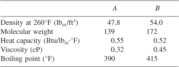
![]()
[Ans.: X = 0.68.] [From California Professional Engineers’ Exam.]
What five things are wrong with this solution? The reaction in P5-10B is carried out in a variable volume, constant-pressure batch reactor with pure A initially. If it takes 2 hours for the volume to decrease by a factor of 2 (i.e., from 2 dm3 to 1 dm3) when the initial concentration A is 1.0 mol/dm3, what is the specific reaction rate constant?
Solution
![]()
Integrating
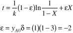
For the volume to decease by a factor of 2 then X = 0.5 at t = 2h. Rearranging (P5-21.2) and solving for k

The reversible isomerization
![]()
follows an elementary rate law. If Xe is the equilibrium conversion,
a. Show for a batch and a PFR: ![]()
b. Show for a CSTR: ![]()
c. Show that the volume efficiency is
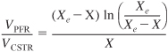
and then plot the volume efficiency as a function of the ratio (X/Xe) from 0 to 1.
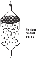
The irreversible first-order (wrt partial pressure of A) gas-phase reaction
A → B
is carried out isothermally in a “fluidized” catalytic CSTR containing 50 kg of catalyst (see margin figure).
Currently, 50% conversion is realized for pure A entering at a pressure of 20 atm. There is virtually no pressure drop in the CSTR. It is proposed to put a PBR containing the same catalyst weight in series with the CSTR. The pressure drop parameter for the PBR, α, given by Equation (5-29) is α = 0.018 kg–1. The particle size is 0.2 mm, the bed porosity is 40%, and the viscosity is the same as that of air at 200°C.
a. Should the PBR be placed upstream or downstream of the CSTR in order to achieve the highest conversion? Explain qualitatively using concepts you learned in Chapter 2.
b. What is the conversion exiting the last reactor?
c. What is the pressure at the exit of the packed bed?
A microreactor similar to the one shown in Figure P5-24B from the MIT group is used to produce phosgene in the gas phase.
CO + Cl2 → COCl2
A + B → C
Figure . Figure P5-24B Microreactor.
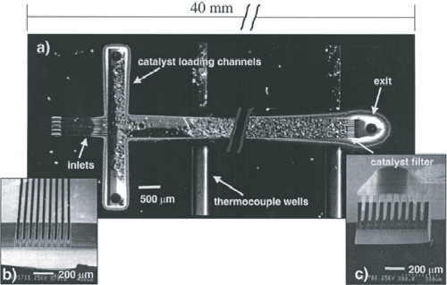
Courtesy of S. K. Ajmera, M. W. Losey, K. F. Jensen, and M. A. Schmidt, AIChE J. 47, 1639 (2001). (Article titled “Microfabricated cross-flow chemical reactor for catalyst testing.”)
The microreactor is 20 mm long, 500 μm in diameter, and packed with catalyst particles 35 μm in diameter. The entering partial pressure of A is 231 kPa (2.29 atm), and the entering flow to each microreactor is equimolar. The molar flow rate of CO is 2 × 10⁻⁵ mol/s and the volumetric flow is 2.83 × 10⁻⁷ m3/s. The weight of catalyst in one microreactor: W = 3.5 × 10⁻⁶ kg. The reactor is kept isothermal at 120°C. Because the catalyst is also slightly different than the one in Figure P4-24B, the rate law is different as well:
![]()
Additional information:
α = 3.55 × 10⁵/kg catalyst (based on properties of air and φ = 0.4)
k = 0.004 m6/(mol · s · kg catalyst) at 120°C
υ0 = 2.83 · 10–7 m3/s, ρ = 7 kg/m3, μ = 1.94 · 10–5 kg/m · s
Ac = 1.96 · 10–7 m2, G = 10.1 kg/m2 · s
a. Plot the molar flow rates FA, FB, and FC, the conversion X, and pressure ratio y along the length (i.e., catalyst weight, W) of the reactor.
b. Calculate the number of microreactors in parallel needed to produce 10,000 kg/year phosgene.
c. Repeat part (a) for the case when the catalyst weight remains the same but the particle diameter is cut in half. If possible, compare your answer with part (a) and describe what you find, noting anything unusual. [Hint: Recall Example E5-5 part (c).]
d. How would your answers to part (a) change if the reaction were reversible with KC = 0.4 dm3/mol? Describe what you find.
e. What are the advantages and disadvantages of using an array of microreactors over using one conventional packed-bed reactor that provides the same yield and conversion?
f. Write a question that involves critical thinking, and explain why it involves critical thinking. [See Preface, Tables P-1 and P-2.]
A very proprietary industrial waste reaction, which we’ll code as A → B + S is to be carried out in a 10-dm3 CSTR followed by a 10-dm3 PFR. The reaction is elementary, but A, which enters at a concentration of 0.001 mol/dm3 and a molar flow rate of 20 mol/min, has trouble decomposing. The specific reaction rate at 42°C (i.e., room temperature in the Mojave desert) is 0.0001 s–1. However, we don’t know the activation energy; therefore, we cannot carry out this reaction in the winter in Michigan. Consequently this reaction, while important, is not worth your time to study. Therefore, perhaps you want to take a break and go watch a movie such as Dances with Wolves (favorite of the author), Namesake, Julie and Julia or Avatar (3D).
Ethyl acetate is an extensively used solvent and can be formed by the vapor-phase esterification of acetic acid and ethanol.

The reaction was studied using a micro-porous resin as a catalyst in a packed-bed micro reactor [Ind. Eng. Chem. Res., 26(2), 198(1987)]. The reaction is first-order in ethanol and pseudo-zero-order in acetic acid. The total volumetric feed rate is 25 dm3/min, the initial pressure is 10 atm, the temperature is 223°C, and the pressure drop parameter, α, equals 0.01 kg–1. For an equal molar feed rate of acetic acid and ethanol, the specific reaction rate is about 1.3 dm3/kg cat -min.
a. Calculate the maximum weight of catalyst that one could use and maintain an exit pressure above 1 atm. [Ans.: W = 99 kg]
b. Write out the CRE algorithm and then solve these equations analytically to determine the catalyst weight necessary to achieve 90% conversion.
c. Write a Polymath program to plot and analyze X, y, and f = υ/υ0 as a function of catalyst weight down the packed-bed reactor. You can either use your analytical equations for x, y, and f or you can plot these quantities using the Polymath program.
The gas phase reaction
A + B → C + D
takes place isothermally at 300 K in a packed-bed reactor in which the feed is equal molar in A and B with CA0 = 0.1 mol/dm3. The reaction is second order in A and zero order in B. Currently, 50% conversion is achieved in a reactor with 100 kg of catalysts for a volumetric flow rate 100 dm3/min. The pressure drop parameter, α, is α = 0.0099 kg–1. If the activation energy is 10,000 cal/mol, what is the specific reaction rate constant at 400 K?
The gas phase reaction
A → B + C
follows an elementary rate law and is to be carried out first in a PFR and then in a separate experiment in a CSTR. When Pure A is fed to a 10 dm3 PFR at 300K and a volumetric flow rate of 5 dm3/s, the conversion is 80%. When a mixture of 50% A and 50% inert (I) is fed to a 10 dm3 CSTR at 320K and a volumetric flow rate of 5 dm3/s, the conversion is 80%. What is the activation energy in cal/mol?
Pressure Drop. The gas phase reaction
![]()
is carried out isothermally at 227°C in a packed-bed reactor with 100 kg of catalyst. The reaction is first order in A and first order in B. The entering pressure was 20 atm and the exit pressure is 1 atm. The feed is equal molar in A and B and the flow is in the turbulent regime with FA0 = 10 mol/min and CA0 = 0.244 mol/dm3. Currently 80% conversion is achieved. Intra particle diffusion effects in the catalyst particles can be neglected. What would be the conversion if the particle size were doubled?
Go to Professor Herz’s Reactor Lab on the DVD-ROM or on the Web at www.SimzLab.com. Load Division 2, Lab 2 of The Reactor Lab concerning a packed-bed reactor (labeled PFR) in which a gas with the physical properties of air flows over spherical catalyst pellets. Perform experiments here to get a feeling for how pressure drop varies with input parameters such as reactor diameter, pellet diameter, gas flow rate, and temperature. In order to get significant pressure drop, you may need to change some of the input values substantially from those shown when you enter the lab. If you get a notice that you can’t get the desired flow, then you need to increase the inlet pressure. In Chapter 10, you will learn how to analyze the conversion results in such a reactor.
• Additional Homework Problems
A number of homework problems that can be used for exams or supplementary problems or examples are found on the DVD-ROM and on the CRE Web site, http://www.engin.umich.edu/~cre.

Bioreactors and Reactions
CDP5-BC
(Ecological Engineering) A much more complicated version of Problem 4-17 uses actual pond (CSTR) sizes and flow rates in modeling the site with CSTRs for the Des Plaines River experimental wetlands site (EW3) in order to degrade atrazine. [See Web Module on the DVD-ROM or the Web.]
CDP5-CB
The rate of binding ligands to receptors is studied in this application of reaction kinetics to bioengineering. The time to bind 50% of the ligands to the receptors is required. [ECRE, 2nd Ed. P4-34] J. Lindeman, University of Michigan.
New Problems on the Web

Green Engineering
CDP-New
From time to time new problems relating Chapter 4 material to everyday interests or emerging technologies will be placed on the Web. Solutions to these problems can be obtained by e-mailing the author. Also, one can go on the Web site, www.rowan.edu/greenengineering, and work the home problem specific to this chapter.
Supplementary Reading
BUTT, JOHN B. Reaction Kinetics and Reactor Design, Second Edition, Revised and Expanded. New York: Marcel Dekker, Inc., 1999.
KEILLOR, GARRISON, Pretty Good Joke Book, A Prairie Home Companion. St. Paul, MN: Highbridge Co., 2000.
LEVENSPIEL, O., Chemical Reaction Engineering, 3rd ed. New York: Wiley, 1998, Chaps. 4 and 5.
Recent information on reactor design can usually be found in the following journals: Chemical Engineering Science, Chemical Engineering Communications, Industrial and Engineering Chemistry Research, Canadian Journal of Chemical Engineering, AIChE Journal, Chemical Engineering Progress.