
2.5.1 CSTRs in Series
The first scheme to be considered is the two CSTRs in series shown in Figure 2-4.
Figure 2-4. Two CSTRs in series.

For the first reactor, the rate of disappearance of A is –rA1 at conversion X1.
A mole balance on reactor 1 gives
In – Out + Generation = 0
![]()
The molar flow rate of A at point 1 is
![]()
Combining Equations (2-19) and (2-20), or rearranging

In the second reactor, the rate of disappearance of A, –rA2, is evaluated at the conversion of the exit stream of reactor 2, X2. A steady state mole balance on the second reactor is
In – Out + Generation = 0
![]()
The molar flow rate of A at point 2 is
![]()
Combining and rearranging
![]()
![]()
For the second CSTR, recall that –rA2 is evaluated at X2 and then use (X2–X1) to calculate V2.
In the examples that follow, we shall again use the molar flow rate of A used in Example 2-1 (i.e., FA0 = 0.4 mol A/s) and the reaction conditions given in Table 2-3.
Example 2-4. Comparing Volumes for CSTRs in Series
For the two CSTRs in series, 40% conversion is achieved in the first reactor. What is the volume of each of the two reactors necessary to achieve 80% overall conversion of the entering species A? (See Table 2-3.)

For reactor 1, we observe from either Table 2-3 or Figure 2-2B that when X = 0.4, then
![]()
Then, using Equation (2-13)
![]()
For reactor 2, when X2 = 0.8, then ![]()
using Equation (2-24)

The shaded areas in Figure E2-4.1 can also be used to determine volumes of a CSTR 1 and CSTR 2.
Figure E2-4.1. Two CSTRs in series.
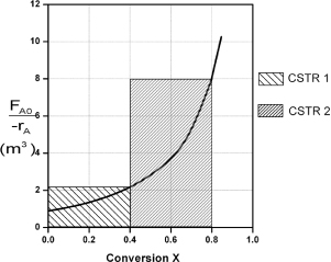
Note again that for CSTRs in series, the rate –rA1 is evaluated at a conversion of 0.4 and rate –rA2 is evaluated at a conversion of 0.8. The total volume for these two reactors in series is
V = V1 + V2 = 0.82 m3 + 3.2 m3 = 4.02 m3 = 4020 dm3
To achieve the same overall conversion, the total volume for two CSTRs in series is less than that required for one CSTR.
By comparison, the volume necessary to achieve 80% conversion in one CSTR is
![]()
Notice in Example 2-5 that the sum of the two CSTR reactor volumes (4.02 m3) in series is less than the volume of one CSTR (6.4 m3) to achieve the same overall conversion.
Analysis: When we have reactors in series, we can speed our analysis and calculations by defining an overall conversion at a point in the series, rather than the conversion of each individual reactor. In this example, we saw that 40% was achieved at point 1, the exit to the first reactor, and that a total of 80% conversion was achieved by the time we exit the second reactor.
Approximating a PFR by a large number of CSTRs in series
Consider approximating a PFR with a number of small, equal-volume CSTRs of Vi in series (Figure 2-5). We want to compare the total volume of all the CSTRs with the volume of one plug-flow reactor for the same conversion, say 80%.
Figure 2-5. Modeling a PFR with CSTRs in series.

From Figure 2-6, we note a very important observation! The total volume to achieve 80% conversion for five CSTRs of equal volume in series is “roughly” the same as the volume of a PFR. As we make the volume of each CSTR smaller and increase the number of CSTRs, the total volume of the CSTRs in series and the volume of the PFR will become identical. That is, we can model a PFR with a large number of CSTRs in series. This concept of using many CSTRs in series to model a PFR will be used later in a number of situations, such as modeling catalyst decay in packed-bed reactors or transient heat effects in PFRs.
Figure 2-6. Levenspiel plot showing comparison of CSTRs in series with one PFR.
