2.3 DERIVATION OF THE TRANSMISSION LOSS FORMULA
This section presents an easier method for derivation of the transmission loss formula. Fig. 2.1 represents two generating units 1 and 2 feeding a number of loads, totaling to IL through a large transmission network. Out of the many branches within the network, consider a branch (any three-phase transmission line) designated as b.
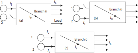
Fig 2.1 Network with two generators feeding a large number of loads, and any one branch b of network
Let the switch in Fig.2.1(a) be open. Then the total load current IL is supplied by generator 1 only. With generator 1 acting alone, the current in the line b is Ib1 whereas the generator current is I1.
Now define current distribution factor ab1 as:
Similarly, let the switch in Fig.2.1(b) be open and the total load current IL be supplied by generator 2 only. With generator 2 acting alone, the current in the line b is Ib2 whereas the generator current is I2.
Now define current distribution factor ab2 as:
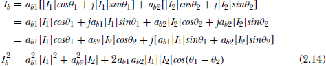
When both the generators are connected to supply the load current, the current through the branch b i.e. Ib can be obtained by applying the principle of superposition as:
The current distribution factors are taken as real numbers owing to the following assumptions:
- The phase angle of all load currents are the same.
- The ratio X/R for all transmission lines in the transmission network is the same.
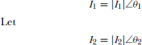
Where θ1, θ2 are the phase angles with respect to a common reference.
From Fq.(2.12).
Now, let
P1, P2 = 3-Phase real power outputs by generators 1 and 2 respectively.
I1 = (P1/![]() × V1cosθ1); I2 = (P2/
× V1cosθ1); I2 = (P2/![]() × V2cosθ2)
× V2cosθ2)
cosθ1, cosθ2 = power factors at generator ends 1 and 2 respectively
V1, V2 = bus voltages at generator ends 1 and 2 respectively
Rb is the resistance of branch b
Let k be the number of branches in the transmission network.
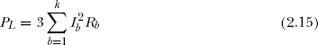
Now, the total transmission loss in the entire network is given by
Substitute I2b from Eq. (2.14) in Eq.(2.15)
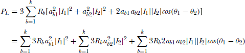
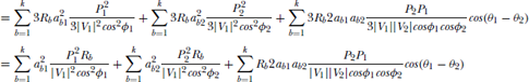
Substituting I1 and I2
The above loss equation in terms of B-coefficients can be written as:
where,
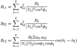
The terms B11, B12 and B22 are called loss coefficients or B-Coefficients. The units of B-coefficients are in MW–1 when the voltages are in KV and branch resistances in ohms.
B-coefficients for multi-machine power systems.
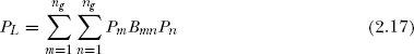
Let Eq. (2.16) be extended for a power system with ng number of generators. Total transmission losses in the system are:
Where Bmn are elements of the S-Matrix.
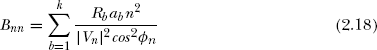
Diagonal terms in the B-Matrix:
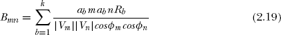
Off-Diagonal terms in B-Matrix:
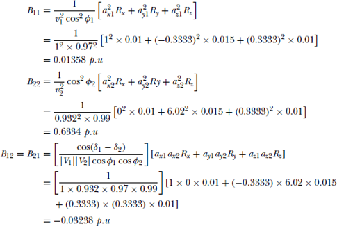
Expanding Eq.(2.17).
In the matrix form of Eq.(2.20),
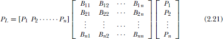
In the condensed form, Eq.(2.21) can be written as
Example 2.1
A four-bus power system network is shown in Fig 2.2(a).
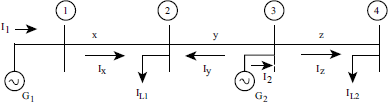
Fig 2.2(a)
Currents flowing in the lines are marked and are given as:
The branch impedances are:
Take voltage at bus 1 as ![]() p.u and base MVA as 100. Compute B-coefficients of the network.
p.u and base MVA as 100. Compute B-coefficients of the network.
Solution:
The load currents at bus 2 and bus 4 are:
Determination of current distribution factors:
Step-1: Let us assume that the total load be supplied by generator G1 alone.
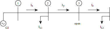
Fig 2.2(b)
IL = Total load current = IL1 + IL2 = 9 – j 2.25 p.u referring to Fig.2.2(b), the current distribution factors can be determined as below.
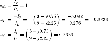
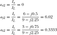
Step-2: Let the total load be supplied by generator G2 alone.
Referring to Fig 2.2(c), the current distribution factors are computed as shown below:
With the help of Fig. 2.1(a), the bus voltages can be determined as follows:
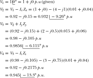
The generator currents and voltages are:
The phase angle at the Generator-1 terminal Φ1 = 0° – (–14.03°) = 14.03°
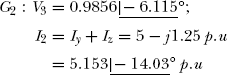
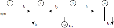
Fig 2.2(c)
The phase angle at the Generator-2 terminal Φ2 = –6.115 – (–14.03°) = 7.915°
The plant on generator power factors are:
The current phase angles at G1 and G2 terminals are:
Therefore, cos(δ1 – δ2) = cos 0° = 1 (i.e. I1 and I2 are in phase)
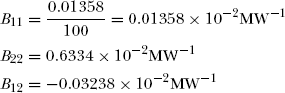
On a 100MVA base the loss coefficients can be obtained by dividing the p.u values by 100
Note:
The following assumptions are made for simplifying the procedure of computing B-coefficients.
- All load currents have the same phase angle with respect to a common reference. It can be seen in Example 2.1, that
IL1 = 6 – j 1.5 = 6.18
 p.u and
IL2 = 3–j0.75 = 3.092
p.u. The phase angle of both the load currents is the same i.e., 14°. - The X/R ratio for all branches of the network are the same. It can be seen in Example 2.1 that the X/R ratio of the branches x, y and z are the same and its value is 4.
The above two assumptions are essential to make the current distribution factor as real numbers, rather than complex numbers.
- Voltage magnitudes at the generator buses remain constant.
- The phase angles between generator bus voltages and currents for all the generating units are the same. In other words, power factor at each plant remains constant.
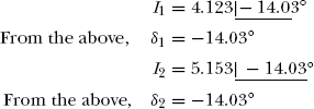
It can be seen in Example 2.1 that the Generator-1 current I1 = 4.123
 and Generator-2 current I2 = 5.153
  That is, δ1 = δ2 = – 14.03°.
Example 2.2
Consider the power system shown in Fig.2.3.
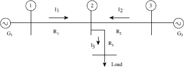
Fig 2.3 A Two Generator Power System
The power loss equation is represented as PL = B11P21 + 2B12P1P2 + B22P22. All the terms in the equation for PL are standard notations. The resistances of lines are marked in the figure. Compute the B-coefficients in terms of resistances.
Solution:
From the figure,
where,
The total power loss in the system is:
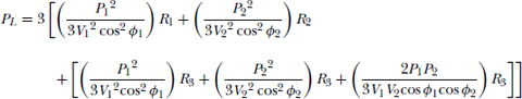
Simplying the above,
Representing the above in the standard form,
where
and
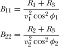
Example 2.3
The power system in Example 2.2 is modified as shown in the Fig. 2.4. Compute the B-coefficients
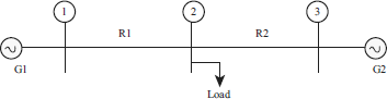
Fig 2.4 Power system with two generators
Comparing Fig.2.3 and Fig.2.4, it can be understood that R3 = 0 in this case. Substituting R3 = 0,
The modified loss equation is
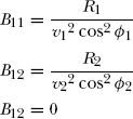
Example 2.4
The power system in the Example 2.2 is modified as shown in the Fig 2.5. Compute the B-coefficients.
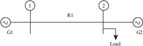
Fig 2.5 Load is connected near Generator-2
Solution:
In this case, the load is connected near Generator-2.
By substituting R2 = R3 = 0, the B-coefficients are:
The modified loss equation is:
Any amount of power supplied by G2 will not produce losses.