4.7 SYNCHRONOUS MACHINES
In transient stability studies, particularly those involving short periods of analysis in the order of a second or less, a synchronous machine can be represented by a voltage source at the back of transient reactance that is constant in magnitude but changing its angular position, neglecting the effect of saliency, and assuming constant flux linkage and a small change in speed.(Refer Fig 4.7)
Where Et = machine terminal voltage.
E′ = voltage back of transient reactance.
It = machine terminal current.
ra = armature resistance.
X ′d = transient reactance.
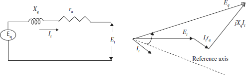
When saliency and changes in field flux linkage are taken into account, the three-phase ac quantities of synchronous machines can be divided into direct axis and quadrature axis components (Refer Fig. 4.8).
The voltage behind the quadrature axis synchronous reactance is given by
Where Eq = oltage back of quadrature axis
xq = quadrature axis synchronous reactance
The sinusoidal flux produced by the field current acts along the direct axis. The voltage induced by field current lags this flux by 90° and therefore is on the quadrature axis. This voltage is given by
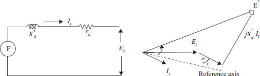
Fig 4.7 Equivalent circuit
where
EI – voltage proportional to the field axis
xd – direct axis synchronous reactance
xq – quadrature axis synchronous reactance
Id – direct-axis component of machine terminal current
Iq – quadrature axis component of machine terminal current.
The phasor diagram for E1 can be shown in Fig. 4.9.
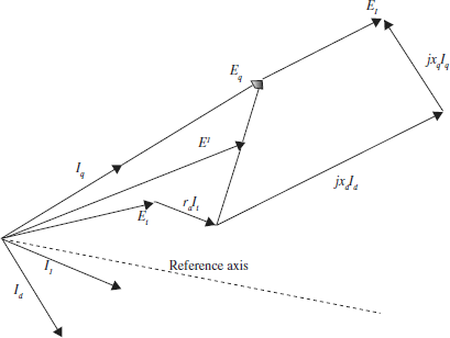
Fig 4.9 Phasor diagram for determining the quadrature-axis component of voltage behind transient reactance