5.1 INTRODUCTION
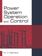
Load demand changes constantly in a power system, and in accordance with the change, power input also varies. If the input–output balance is not maintained, a change in frequency occur. Hence, the frequency of control is achieved through a speed governor mechanism. The role of the governor is to control the relation between speed and load. If the load on the turbine increases, the speed of the governor decreases. The frequency may normally vary by 5 percent between light load and full load conditions. Consider two machines running under parallel operation as shown in Fig 5.1. Load sharing between the two machines is as follows. If there is a change in load either at E1 or E2, the generation of E2 alone is regulated to adjust this change so as to have constant frequency. This method of regulation is known as parallel frequency regulation. If the change in load at a particular area is taken care of by the generator in that area the tie-line loading remains constant. This is known as flat tie-line loading control. In a large inter-connected power system, manual regulation is not feasible. Important control loops in power system are
- Frequency control
- Automatic voltage control
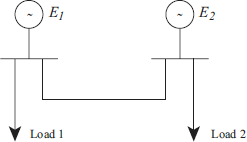
Fig 5.1 Parallel operation of two generators
In this chapter the frequency control will be discussed. The reasons for keeping frequency constant are as follows:
- In a large interconnected power system network the real and reactive power are constantly changing with tailing and rising loads that never remain constant,
- Frequency and voltage of a system are maintained at their normal values by monitoring load variations and using suitable control actions to match the real and reactive power generations with the load demand and the losses in the system at a given time.
- System frequency is closely related to real power balance in the power system network; the system frequency is mainly controlled by real power balance in the system.
- As load increases on a generating unit, more amount of real power is to be supplied to it. This is immediately received by the unit kinetic energy in the rotating part, thereby reducing the kinetic energy and hence the angular velocity or speed of the machine.
- Voltage is controlled by reactive power control in the system.
Load frequency and excitation voltage regulators of turbo generators are shown in Fig 5.2. These controllers are set for a particular operating condition and take care of small changes in load that do not exceed prescribed values. If the change in load becomes large, the controllers must be reset either manually or automatically.
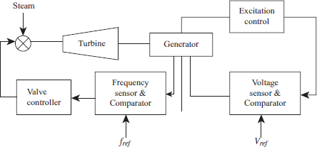
Fig 5.2 Load frequency control with voltage regulators