7.3 LOAD FREQUENCY CONTROL AND ECONOMIC DISPATCH CONTROL
As mentioned earlier, the presence of an integral controller aids us to attain better dynamic response with zero steady state deviation in frequency whenever there is a variation in load. This variation in load also disturbs the an economic dispatch of load. Hence, in addition to an integral controller, an economic dispatch controller should also be provided for satisfactory operation of the power system. The block diagram of a load frequency control with economic dispatch control is shown in Fig 7.3.
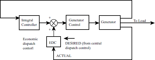
As shown in the block diagram, if there is any variation in load, the load frequency controller, which is fast-acting (within zero seconds) responds and actualises the speed changer (generator control) accordingly. The economic dispatch controller, which is slow acting (one minute), responds to the load change together with the input from the central dispatch control and an error signal is generated. This error signal together with the error signal generated by integral controller actualises the speed changer.
Since the load frequency controller is fast acting and economic dispatch controller is slow acting, the power system may operate with EDC error only for few seconds before the EDC generates a command signal.
Example 7.1
Consider an isolated power system as shown is Fig 7.1 with the following parameters Tp=12sec, KP=80 Hz/p.u MW, R=2 Hz/p.u MW, Ki=0.2, for a load change of 0.2 p.u MW. Obtain the time error in seconds and cycles. Assume Tg = Tt = 0 and system frequency is 50 Hz.
Solution:
From equation (7.3)
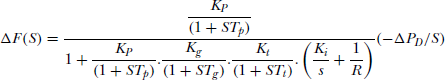
From the given data Tg = Tt = 0, Tp = 12, KP = 80, R = 2, Ki = 0.2, ∆PD = 0.2 also KgKt = 1.
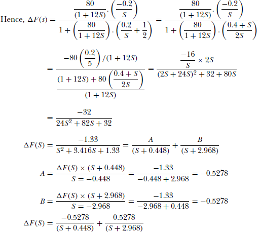
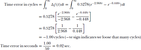
Taking inverse Laplace transform
Example 7.2
For an isolated, integral controlled power system find the value of Ki,critical. The system parameters are given below
Total capacity=1000 MW
Load=600 MW
Inertia constant=5.0 sec
Regulation R=4 %
The nominal operating frequency is 50 Hz and the system load increases by 1 percent if the system frequency increases by 1 percent.
Solution:
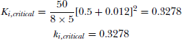
We know from Eqn (7.14)
![]()
R = 0.04 × 50 = 2 Hz/p.u MW
f o = 50 Hz and H = 5 sec from given data. Hence,