8.5 REACTIVE POWER FLOW IN AN UNCOMPENSATED TRANSMISSION LINE
Let us consider a transmission line connecting two busses (a simple model) as shown in Fig 8.5. Let the R value of the transmission line be zero. Hence the losses in the line is zero. Let the load be such that it draws | I | amps at a terminal voltage of | I | volts. Now, the reactive power absorbed by the line will be
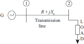
Fig 8.5 Uncompensated transmission line
We know that a transmission line consists of series inductance and shunt capacitance.
Case I: If the reactive power generated by the line given by ![]() equals the reactive power absorbed, then
equals the reactive power absorbed, then
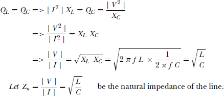
Therefore, the natural power transmitted in the line is given by
The above expression indicates that the reactive power generated is equal to the reactive power absorbed, this occurs when the line is terminated by a resistance equal to its loading surge inpedance. This condition introduces a flat voltage profile over the complete distance of the transmission line as shown in Fig. 8.5(a)
Case II: If the reactive power generated in the line is more than the reactive power absorbed i.e., QC > QL then,
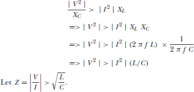
This implies that Z > Zn, where Zn is the natural inpedance of the line. This condition introduces a voltage rise over the complete distance of the transmission line as shown in Fig. 8.6(b)
Case III: If the reactive power absored by the line is more than the reactive power generated (i.e) QL > QC then
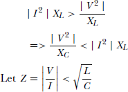
Which implies that Z < Zn, where Zn is the natural inpedance of the line. This condition introduces a voltage, say over the complete distance of the transmission line as shown in Fig. 8.6(c)