
4
DC and AC Electricity
OBJECTIVES: After studying this chapter, you will be able to
- Differentiate between two main types of electricity
- Define direct current electricity
- Define alternative current electricity
- Explain what an electric circuit is
- Draw a schematic representation of an electric circuit
- Understand the basic components in any electric device or circuit
- Describe what a resistor in an electric circuit is and what effect it has on the circuit
- Describe what an inductor is and what it does
- Describe what a capacitor is and its role in electricity
- Describe resistance
- Explain what inductance is and how it is determined
- Explain what capacitance means and how it is calculated
- Understand two important properties of electricity, current and voltage
- Define electric current and electric voltage and make an analogy between electricity and water flow in a pipeline
- Name some of the units used to measure electricity and electric components
New terms: AC circuit, alternating current, alternative current, ampere, capacitance, capacitor, circuit, coil, cycle, cyclic waveforms, DC circuit, direct current, electromotive force, Farad, ferromagnetic, frequency, Henries, Hertz, inductance, inductor, ohm, omega, potential difference, resistance, resistor, sinusoidal, specific resistance, volt, voltage, waveform
4.1 Introduction
Even if you do not know much about electricity yet, you use it every day. Unless you live in remote locations, or in undeveloped places, electrical networks can be seen and are in use. Even in those remote places, electricity can exist in other forms. You are familiar with batteries and know that they come in different sizes. Also, you are familiar with electricity that you have at home because you have lights, a refrigerator, a kitchen range (if electric), and so on. In all these devices, there is a switch to turn the device on and off, and there are wires between the device and the source of electricity. We are going to study what the source of electricity is and what is inside these devices, what happens when the switch is turned on, and how we can illustrate all of these in paper drawings. Furthermore, you learn what the difference is between the electricity from a battery and the one that is used for home lights.
4.2 Electricity Basics
We learned in Chapter 3 that in metals there are between 1 and 3 valence electrons and also that these electrons can be excited with heat (their level of energy increases). Electricity is the flow of electrons in any conductor. There are billions of these electrons even in a tiny piece of metal. When the electrons move together in one direction (even if for short periods of time), they form an electric current. Thus, electric flow implies simultaneous motions of billions of electrons.
Obviously, there must be a force to move all electrons in one direction; otherwise, there is no reason why they move in a particular direction, instead of moving in their orbits or in the case of free electrons (valence electrons with little bonding force that can easily travel from the orbit of one atom to another) moving randomly in all directions. Any source of electricity (such as a battery or a generator) provides the force to create this motion of electrons with a defined pattern.
An analogy can be made between electricity and water flow in a pipeline. This often helps to better understand the rules and facts of electric flow, because water flow can be observed and pictured in mind, whereas electricity and electric flow are obscure. You can imagine each drop of water as an electron. First, there has to be a force moving all the water in one direction. In the absence of such a force, the water stands still. Nevertheless, the following three points must be always kept in mind:
- Even if the water is not flowing, drops of water can have local motion, like in waves generated by wind.
- Not all the water drops have the same uniform motion (parallel with each other and with the same speed).
- The path of water as a whole is defined by the waterway or the pipeline.
In electricity, the force behind the motion of electrons is called electro-motive force. This force pulls or pushes the electrons through a path along which they can move (e.g., through a conductor).
Electromotive force: Electrical potential difference causing electrical current between two points. A battery or an electric generator is a source of electromotive force, measured in volts.
Electricity is the flow of electrons. Motivation force causing their motion is called electromotive force.
In the flow of water in a pipe, or a stream, the current is defined in gallons per minute (or other units, such as liters per second in the metric system). This implies that if at some point the pipe is smaller in size, the water speed increases to maintain the flow rate. You can imagine the same thing for the flow of electrons. However, this analogy is not always true or perfect, and it will be combined with other facts.
If you consider the flow of electricity in a lightbulb (an electric device), you notice that flow of electrons is the same in the wire connecting the device (the lightbulb) to the electric source. While the device gets hot, the wire does not. The reason is that the electrons spend more energy in passing though the device. This becomes clearer for you in the following sections.
4.3 Electricity Effects and Electrical Devices
You have noticed the home electricity that is used for lighting, cooking, warming (heater), cooling (refrigerator), and motion (motors in home and garden devices). But, if you want to list the effect of electricity, you should not list the above. These devices use electricity as the source of energy to do their function, which depends on the device, its components, and the media used in them.
Electricity has three effects, and all we can do with electricity is based on one or more of these effects. These are thermal, magnetic, and chemical effects. The light in an incandescent lightbulb is due to thermal effect. The light in a fluorescent lightbulb is a result of thermal and chemical effects. All the motors work because of the magnetic effect of electricity.
The main effects of electricity are thermal, magnetic, and chemical effects. All electric devices function based on one or more of these effects.
All the thermal devices (e.g., heaters and stove) use the thermal effect of the electricity. All the incandescent lightbulbs also work based on the thermal effect, which heats the element to a high temperature and results in emitting visible light.
The magnetic effect of electricity is the basis of the function of all the electric motors and generators. Electric motors and generators have wire windings in them that enhance the magnetic effect, as we will discuss in later chapters. Also, electric magnets (called electromagnets) are commonly used in many domestic and industrial applications.
In electric motors and generators, some electricity is converted to heat. Although this is unwanted because it is intrinsic to the use of electricity one cannot avoid this heat, which is a waste of energy. In other words, when using one effect of electricity, we may not be able to block the other effects.
You may have heard of using electricity to convert water into hydrogen and oxygen or for decomposing other compound materials, too. This is based on the chemical effect of electricity. This effect is frequently used in chemical and other industries. One good example is electroplating, which is covering the surface of a metal with another metal for protection or cosmetic reasons.
In a refrigerator (and other cooling devices), electricity is used in the compressor to compress the refrigerant, but the rest of the system is not electric and does not use electricity.
4.4 Main Electric Components
All the apparatuses that you can name as electric devices can be composed of one or more of the main electric components. An electric device is connected to electricity by means of a switch and some wires; it may have a fuse as well, and if it uses electricity from the wall outlet, it has a plug. Nevertheless, by main components we mean the following three basic elements: resistor, inductor, and capacitor.
We need to learn these components very well and understand their functions, before moving forward. Basically, these three elements have three different functions and their names when addressed imply that each one purely functions as expected, without crossing the border to functions of the other two. Any electric circuit can be composed of one or more devices and some wires. But, ultimately, it can be decomposed into a combination of these basic elements. Not every device should necessarily contain all three of these basic elements. For instance, a lightbulb has only a filament; that is, it consists of a resistor only. On the other hand, whenever we have a wire winding (like in a motor or an electromagnet), it can be considered a coil. A coil consists of a resistor and an inductor. A capacitor, however, is a storage device for electricity. It can come in various sizes. Fluorescent lights and flashes in cameras use capacitors. Capacitors are used in many other devices or circuits, such as in motor circuits.
Coil: Any wire wound in circles to form a helix, usually with a core to enhance the inductance.
In this section these basic components are introduced, but we will discuss more about them in the following sections and we will discuss direct current and alternating current electricity.
There are three main basic electric elements: resistor, inductor, and capacitor.
4.4.1 Resistor
A resistor or a purely resistive device consumes electric power and converts it into heat. Examples of resistors are all electric lightbulbs filaments, electric kettle, heater, iron and stove elements, and any other heating element in a device such as electric water heater. Note that an incandescent lightbulb is not meant to convert electricity to heat like a heater, but to light up. However, in this process the filament is heated to a high temperature to emit light. Thus, the lightbulb gets hot, and it can be treated similar to an electric heater element.
Resistor: (a) An electric component that only exhibits resistance (and no other reaction) to the flow of electricity. (b) Any of the standard components, made in different physical sizes, that are used in electrical and electronic circuits to absorb electrical energy.
The way a resistor works is that it introduces resistance to electric flow. In passing through such an element, electrons must consume more energy. This energy appears as heat in the element.
Resistance: (in electricity) (a) The property of resisting (but not blocking) the flow of electric current, leading to limiting the flow and absorbing (consuming) electric energy. Resistance is measured in ohms (Ω). (b) One of the three basic components that any electric load (a device using electricity) can be assumed to be composed of.
A heater element or lightbulb filaments are made up of a wire usually made out of tungsten or a tungsten alloy. The primary role of such an element is converting electricity to heat. Nevertheless, in many (electronic) circuits, such as in radio and television, the primary role of a resistor can be something else, but in the process a resistor gets hot as well. In such a case the heat must be removed by cooling. Figure 4.1 shows a wire-wound resistor. For protection and portability, such a resistor can be encapsulated in a ceramic casing.
Resistors of the second category (for electronic circuits) are available in various standard sizes and forms. A more detailed description of the resistors used in electronic devices is given in Appendix E. Figure 4.2 shows some examples of these resistors that are made of other material than a metal and have a different structure than being wound. When used in an electric circuit, a special symbol is used to represent a resistor. Figure 4.3 shows the symbol for a resistor.
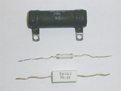
Figure 4.1
Wire-wound resistor.
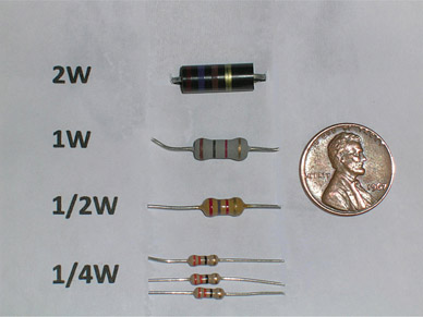
Figure 4.2
Examples of resistors used in electric and electronic devices.
Figure 4.3
Symbol for a resistor in an electric circuit.
4.4.2 Inductor
Inductor: A winding (a coiled wire) with only magnetizing property and without any electric resistance. Physically it is not possible to have a pure inductor, but at certain conditions, particularly high-frequency electric signals, the resistance of the coiled wire can be ignored in comparison with its inductance.
An inductor is a storage device that can store electric energy by turning it into magnetism. This storage act is not similar to storing energy in a battery. Rather, it is a short-duration storage for a very small amount of electricity. Practically, a winding as shown in Figure 4.4 can do this job and behaves as an inductor. That is, a coil made of a wire wound around a support can be regarded as an inductor. An inductor can have a core. The core can be of any form such as a cylinder or prism, and it can be made out of any material such as paper, wood, plastic, or metal. As we discuss later, for a metallic core to be useful (and not as a support) it must be a ferromagnetic (like iron and steel or certain special alloys) material.

Figure 4.4
A coil (winding of wire) is the basis of an inductor.
Ferromagnetic: Type of material from the iron family that is suitable for magnetization.
Theoretically, an inductor has only the storage capability without converting any electricity into heat. This is to say that a coil of metal should ideally have no resistance to electric flow. But, in practice, a coil is made of wire, and the wire behaves as a resistor. The physical size of a coil (length, diameter, number of turns of the winding) and other factors define the property of a coil as an inductor. In practice, a coil can be very well accepted as an inductor if the resistor part of it is small (see Section 4.10).
Figure 4.5 shows the symbols for a coil with or without a (ferromagnetic) core. A ferromagnetic core enhances the inductor property of a coil. Figure 4.6 shows the physical shape of a coil.
An inductor stores electric energy, but this storage action is in a small scale and with short duration.

Figure 4.5
Symbol for inductors. (a) Coil without core and (b) coil with core.
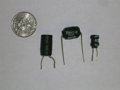
Figure 4.6
Examples of inductors.

Figure 4.7
Symbol for a capacitor. (a) Capacitor without polarity and (b) capacitor with polarity.
4.4.3 Capacitor
A capacitor is another electricity storage device but completely different and based on a different structure and property than an inductor. A capacitor stores energy in the form of electric field, like a battery. Attention has to be paid to the fact that, although we use the term storing electric energy in an inductor and a capacitor, this storage is very small relative to what a battery does. In particular, the difference is more meaningful in terms of the time this energy can be reused. We may charge a battery, leave it charged for a long time, and then use the stored electricity for say one month. This is much beyond the storage in a capacitor or an inductor. For instance, if instead of a (rechargeable) battery, we use a capacitor, it gets charged in a few seconds or less (can be in microseconds); after some time, if the stored energy is not leaked out, we may use it for a period around the same that it took for charging. Think of the duration of a flash in photography.
You may question what type of storage such a function is useful for. Well, one example is storing numbers in a calculator or a computer during its number processing. We will discuss about the other applications of a capacitor in the later chapters.
Figure 4.7 shows the symbol of a capacitor in a circuit. As shown, capacitors are either polarized (i.e., one terminal must be always connected to the positive side and the other terminal to the negative side of the circuit) or nonpolarized (i.e., it does not matter which side is connected to positive). The basic structure of a capacitor is two metallic plates separated by an insulator. In practice, the two plates and the insulator material between them are rolled to form a cylinder, as shown in Figure 4.8. In this way, a more compact and portable package is obtained. Very small capacitors are made differently, and come in a different shape than cylindrical form. Figure 4.9 shows some examples of capacitors.
Circuit: Any combination of electric and electronic components connected together by wires to be connected to an electric source.
A capacitor stores electric energy, like an inductor, but in a different way. This storage action is not on the same scale as in batteries.
4.5 Electric Circuit
To use electric energy in any device, one needs to connect the device to the electric supply by wires. An electric circuit represents the connection of a device to the electric source. In the simplest form a circuit must have a source to which one or more devices are connected through two wires. One may also include a switch and a fuse. A switch is a control device, and a fuse is a safety device.

Figure 4.8
Basic construction of a capacitor.
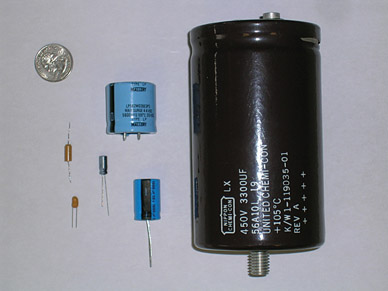
Figure 4.9
Capacitors with various sizes and shapes.
The role of the switch is to control energizing the load when desired. The role of the fuse is to protect the load and the source from damage. If something goes wrong, a fuse disconnects a device from electricity, thus saving the device from getting damaged; also, it can prevent a potential fire in case a heating element is involved. We discuss more about this protection in later chapters. For now, know that a fuse is an important part of any electric circuit. Figure 4.10 shows such a simple circuit.
A fuse is a necessary and important part of any electric circuit.
Figure 4.11 depicts a circuit for a light connected to electricity. This is the physical arrangement for the wires and the light, switch locations, and so on. Whereas this diagram is good for wiring purposes, it is not so suitable for analysis that is needed before a wiring diagram can be produced. For analysis purposes it is customary to simplify this diagram and show all the components inside a circuit by their respective symbols and connect them together in the logical way and order. More importantly, because all devices are made up of the three basic aforementioned elements, any device is represented by its equivalent basic elements. In this sense, the circuit in Figure 4.11 is represented as illustrated in Figure 4.12.
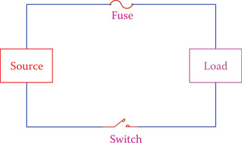
Figure 4.10
Simple electric circuit.
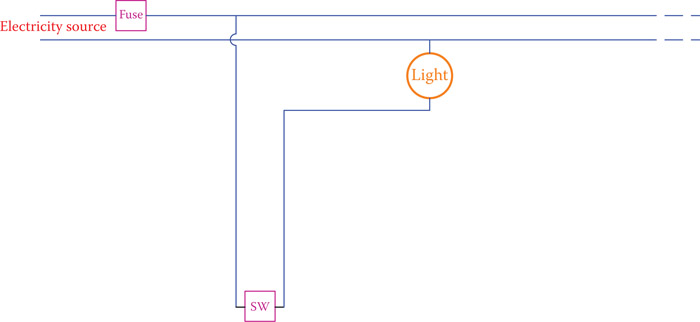
Figure 4.11
Sample of a circuit at home lighting.
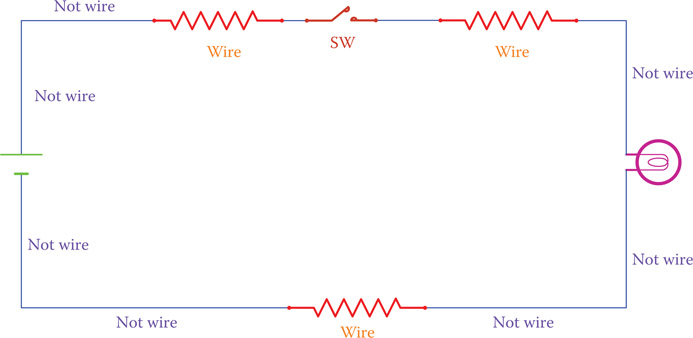
Figure 4.12
Representation of the electric circuit in Figure 4.11.
Note that in Figure 4.12 for each component a standard symbol is used. A pair of parallel short and long lines denote a battery. (Here we used a battery as the electricity source.) Moreover, all the wires are represented by a resistor denoting the value of the resistor (see Section 4.10), and the lines connecting various elements are just drawing lines (showing the order of connections) and they do not represent wires. This is very important, and you must pay attention to it all the time.
In Chapter 6 we discuss how to combine all the resistors in the circuit of Figure 4.12 and show them by only one resistor. When the particular function of a device is not of primary importance to the study of the circuit, a device is shown as a load to the electric source in the circuit. In this sense, the electric circuit consists of a load and a source. The source must be capable of driving (energizing) the load.
4.6 Electric Flow
Electricity is the flow of electrons in a circuit, as we learned earlier. The electric source provides the supply of electrons and makes them move in a circuit. In this sense, if a circuit has no source, then no electricity, and thus no electric flow, can exist. Also, if a circuit is open (it does not form a loop), there is no path for electrons to flow. Thus, for electric flow we need a power supply and a closed loop. But, how fast is the electric flow and how fast do the electrons move and in what direction?
For electric flow in a circuit, the circuit must be closed, forming a loop.
Electric flow in a circuit is very fast, almost as fast as the speed of light. But, electrons do not (and cannot) move that fast. Electrons move with a speed much slower, around a few inches per second (see Section 5.2). This implies that when we turn a light switch on, the transfer of electric energy to the light is immediate, and we do not need to wait until the electrons start moving and get to the light. That is to say, although electrons can only move a few inches per second, when they get energized, they transfer their energy to the neighboring electrons and this process continues in a chain reaction. As a result, the load receives energy immediately.
As it is universally accepted, electrons have negative charge. Also, as you know, a battery, as a power source, has two terminals, positive and negative. A power source pushes the electrons inside a circuit, and because the circuit must be closed, electrons must circulate. There are two conventions that are used to define the direction of the electric flow in a circuit. Both are valid and can be used in practice. Nevertheless, one should always follow one of them to avoid confusion. These two conventions are
- Electric flow is in the same direction as the flow of electrons; that is, from negative side toward the positive side.
- Electric flow is assumed to be from the positive side to the negative side. This latter is the conventional direction of electric flow.
In this book we employ the conventional electric flow. That is, electric flow is from positive toward negative.
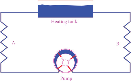
Figure 4.13
Analogy of a pump with an electric power source.
The role of a power supply in an electric circuit can be compared to the action of a water pump in a closed circuit (like in the hot water heating system that the pump is used for circulating water). A pump pushes water to flow. This analogy also can make understanding electric flow and its rules and relationships easier. Think about a pump. It pushes the water by pressurizing it. (So, there is a pressure difference between the two sides of the pump.) Also, there is a flow rate that depends on the pump pressure and the piping that water must flow through. See Figure 4.13.
4.7 DC and AC
We start making a distinction between the two types of electricity in use. If you have not already noticed the difference between the electricity you get from a battery and the electricity used at home, this is the starting point to realize their differences. There are two distinct types of electricity that they have similarities and differences. Their similarity is that they are both electricity, and certain definitions, rules, and formulations associated with their application are the same. Their difference is in the way they are generated, their effects, and most of the relationships associated with their use. The two categories are DC and AC.
DC stands for direct current and AC stands for alternating current or alternative current (both terms are used). In direct current, electrons move only in one direction, from the negative terminal of the power supply through the external circuit to the positive terminal of the power supply. That is, as long as the circuit is closed, there is a continuous motion of electrons all going in one direction. In alternative current, electrons have a back and forth motion. That is, they move in one direction, but after a short period they change direction and move in the opposite direction. They do this continuously as long as the circuit is closed.
Direct current: Type of electricity in which there are positive and negative poles (or sides) and electric current is always in the same direction between the two poles, as opposed to alternative current in which the current direction continuously changes (at a fixed frequency).
Alternating current: Type of electricity in which current continuously and regularly changes direction (i.e., electrons in the wires move back and forth, as opposed to direct current in which electrons move only in one direction).
Alternative current: Same as alternating current.
Note that it is the motion of electrons that delivers electric energy to a device; thus, for alternating current, as long as the electrons are in motion, the electricity flow continues and its effect can be observed.
In the analogy between a pump circulating a liquid and electricity, you can imagine that for direct current the pump always rotates in the same direction and sends the fluid inside the pipes in one direction, whereas for alternating current it alternately switches direction and sends the fluid into the pipes in two directions. For example, as shown in Figure 4.13, for one minute it circulates the fluid clockwise and in the following minute it circulates the fluid counterclockwise.
Normally, in a fluid circuit this is not done. However, to better understand the meaning of alternating current, this assumption is made. Note that the pump used in this circuit is a vane pump, which, in principle, can pump in both directions (other pumps can usually work in one direction). In the circuit illustrated in Figure 4.13, assume that water is heated in the tank and the purpose of circulation is to send hot water to the coils at A and B. We want to show that for the purpose of heating sites A and B, it does not matter in what direction the water circulates. It can also circulate first in the clockwise direction and after a while in the counterclockwise direction. As far as heating is concerned, the direction of circulation and its switching are immaterial. This is exactly what happens in the alternating current. For many (but not all) applications the direction of current does not matter, and more importantly, if the current continuously changes direction, as far as a current exists, we can benefit from the electric energy. For instance, in an electric heater or a lightbulb, the energy in the moving electrons changes to heat. The direction of the motion of the electrons does not play any role.
In the alternating current the interval between switching direction must be constant; otherwise, there will be a chaos. This interval is not long and is much smaller than a second. The number of switches of direction per second is a property of alternating current electricity and plays a significant role. The electric supply at home is alternating current. In North America the number of switching directions is 120 times per second. In European and many other countries it is 100 times per second.
4.8 Electric Potential and Electric Current
Potential difference: The difference in intensity in an electric field or various points in an electric circuit, also called voltage. The potential difference between the + and − terminals in a car battery is around 12 V.
Similar to a fluid flow, there are two parameters associated with electric flow in an electric circuit. These two parameters are of paramount importance and must be well understood. Figure 4.14 helps to better understand these two parameters. Four scenarios are shown in Figure 4.14 for a water stream. In these scenarios, water falls from a higher level to a lower level. This level difference is necessary; otherwise, there will be no flow. As can be seen, in two cases the level difference is large, and in the other two it is small. Also, the amount of water flowing in two cases is large and in the other two cases is small. For electricity we refer to the level difference as potential difference, and it is always this relative difference that causes an electric flow. As depicted in the four scenarios, water can have a large level difference but a small flow rate, or a small level difference but a large flow rate, and so on. The flow rate of electricity is called current intensity or just current. Current determines the rate of electric charge that moves in a circuit. Because electric charge is associated with electrons, current is proportional to the number of electrons that move in one second.
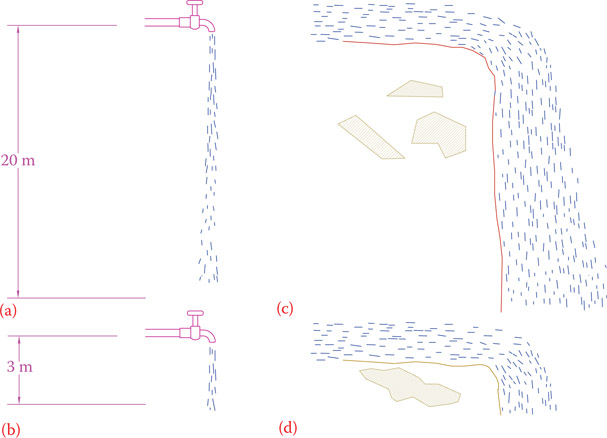
Figure 4.14
Analogy of water level and current with electric voltage and current. (a) High potential difference, low current. (b) Low potential difference, low current. (c) High potential difference, high current. (d) Low potential difference, high current. (From Hemami, A., Wind Turbine Technology, 1E ©2012 Delmar Learning, a part of cengage Learning Inc. Reproduced with permission from http://www.cengage.com/permissions.)
A simpler and more widely used term for potential difference is voltage. The voltage (or potential difference) determines how much electro-motive force is behind the electrons to push them in a circuit. Thus, it depends on the electricity source. For example, the voltage of a small battery (e.g., AA or AAA size) is small, and the voltage of electricity at the wall outlet is much larger. The current, however, depends on how easy or difficult the electrons are allowed to move in a circuit; thus, it depends on the circuit.
Voltage: A main property of electricity representing the intensity of electric charges based on accumulation of electrons. Normally a voltage difference between two points defines the potential for a discharge. Voltage is measured in volts.
Electric current is a measure of the electricity flow rate; it is proportional to the number of electrons that move in 1 sec. It is not the speed of electrons.
To measure the voltage and current, we need to have units for their measurement. Voltage is measured in volt. On a small battery you see the writing “1.5 V,” where V represents volt. Also, if you look at a light-bulb that you use at home, you will see “120 V.” You probably know that one cannot light up this lightbulb with a battery. It is because of this voltage incompatibility. There is one more reason for not being able to light up the above lightbulb with a 1.5 V battery, which we will discuss in Chapter 5.
Volt: The unit for measurement of voltage (or potential difference) in an electric source or load or between two points in an electric circuit. The voltage in a pen size battery is 1.5 V.
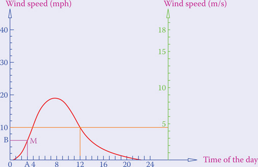
Figure 4.15
Example of a graph.
Graphs and Graphic Presentation of Variables
A graph is a convenient way of illustrating the variation of the values of an entity in terms of one (or more) parameters. For example, the variation of the temperature versus time for a day can be represented by a graph, or the area of a circle versus its diameter can be illustrated by a graph.
In the simplest form a graph has two axes: a horizontal axis and a vertical axis. The values of the changing variable (for example, time in the case of temperature) are shown on the horizontal axis and the values of the entity under study are shown on the vertical axis. Often the parameter on the horizontal axis is called the independent variable, whereas that on the vertical axis represents the dependent variable. Each pair of values of the horizontal and vertical axes define a point, which can be found from drawing two lines from those two points parallel to the axes. This is shown in Figure 4.15, where point M is obtained from point A on the horizontal axis and point B on the vertical axis.
The above graph shows the variation of wind speed during a period of 24 hours for a particular region on a specific day. As can be understood, wind speed is not the same when it blows, and can be zero, too (when there is no wind).*
By this graph one can see the wind speed for a given hour as well as the time for a given wind speed. The values for each can be read from the graduations on the axes. For example, the wind speed at 12 o’clock is 10 mph. Furthermore, this graph has two scales for the vertical axis. Not all graphs need to have this. Here, since wind speed can be measured in mile per hour (mph) or in m/s (meters per second) two scales is very useful. You can see that at 12 o’clock the wind speed is about 4.5 m/s. Notice also that a wind speed of 10 mph corresponds to two points on the horizontal axis. That is, at around 4:00 and at 12:00 the wind speed is 10 mph.

Figure 4.16
Examples of linear graphs.
Note that many graphs are obtained as a result of some calculation. This makes it faster for a user, since instead of performing the calculation one can read the answer from the graph. However, there will be some approximation and inaccuracy in this process.
Sometimes a graph is used only to see the pattern of variation of a variable. In Figure 4.16, for instance, the first graph shows that there is no change in the variable. The second graph (which is a sloped line) depicts that the variable of interest has a linear relationship with the independent variable.
In this example we have assumed that you have 20 similar batteries that you want to carry with you to a remote place for lighting purposes. Suppose that you put them in a box and connect all the positive terminals together and all the negative terminals together. The first graph shows that the brightness of a light connected to these batteries does not change, whatever the number of batteries. The second graph shows that as you increase the number of batteries the weight of the box increases. You can decide how many batteries you take if you cannot carry all.
* This graph should not be confused with another one looking similar to this, in which the horizontal axis is the wind speed and the vertical axis shows the probability of wind at various speeds.
Although, as mentioned earlier the electric current is proportional to the number of electrons that pass in a circuit during a one second period, this is not a convenient unit for measuring the electric current. This is, first, because of the extremely large number of electrons that move and, second, because there is no way of counting those electrons. A better unit for measuring current is ampere, abbreviated amp and denoted by the capital letter A, e.g., 2A (2 amperes, or 2 amps), 3A, and so on.
Ampere: Unit to measure electric current.
Both voltage and current can be measured by the appropriate measuring devices. (See Sections 5.5 and 5.6 for how to measure the current and voltage in a circuit.)
Now that we have learned about voltage, we may graphically illustrate the difference between DC and AC. Graphical illustration of an entity is a very useful and convenient method for understanding and picturing its variation with respect to some changing parameter, or comparing it with some other variables. In the case of electricity, it is usually the time with respect to which we study the values and variation of a particular entity like voltage and current in a circuit. The beginning of time for such a graph is usually when a switch is closed. In this sense the graph for DC electricity from a battery during a short period of time (say a few hours) is as shown in Figure 4.17.

Figure 4.17
Graph of the voltage in a DC source versus time.
In an AC source the voltage changes polarity. This change of polarity is not random and has a desired order. Figure 4.18 depicts some examples of patterns for voltage variation, which, in general, can be categorized as alternating current. These patterns are, however, more used for special purposes in electronic devices such as in radio and TV. Normally, when alternating current electricity is addressed, particularly when comparing DC with AC, a waveform with a sinusoidal pattern, as shown in Figure 4.19, is referenced. The commercial AC electricity has this waveform. In other words, for AC electricity a sinusoidal waveform is desired, and it is always assumed that a source generates electricity with this pattern (see the text on “sinusoidal waveform” in this chapter). If the waveform of electricity is far from a sinusoidal pattern, corrections may become necessary.
Waveform: The form (shape) of variation of a signal (electric or other) that varies with time. The shape of a rectangular waveform, for example, is made up of succeeding rectangles.
Sinusoidal: The most common and preferred waveform for alternating current electricity. The variation of a sinusoidal waveform is according to the values of sine (or cosine) of an angle for 360° (one revolution) change.
Cycle: Pattern of all values that will be continuously repeated in a cyclic variable. For example, in alternative current electricity a cycle is the complete set of positive and negative values based on a sine function of an angle when it varies from zero to 360°.

Figure 4.18
Various alternating current waveforms.
As can be seen from all the illustrated waveforms, a pattern is repeated continuously with respect to time. Each repetition is called a cycle, and all the patterns shown in Figures 4.18 and 4.19 can be called cyclic waveforms. The duration for a cycle is called a period, measured in seconds. The magnitude of a cyclic waveform is called amplitude. Here only three repetitions are shown, but the pattern is assumed to continue infinitely. Because the same pattern is repeated, in order to denote or study the details of a waveform, only one cycle is sufficient.
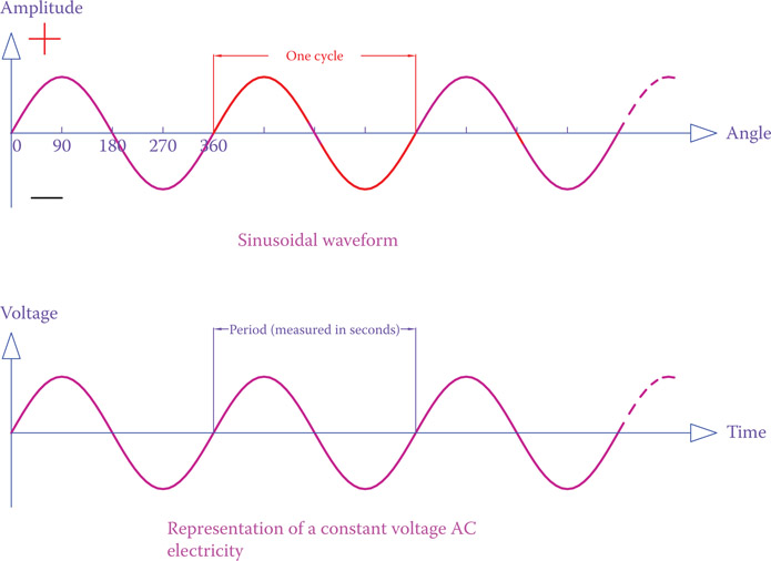
Figure 4.19
Sinusoidal alternating current waveform.
Cyclic waveforms: Waveform corresponding to a variable entity whose variation has a repeat of the same pattern over and over.
Sinusoidal Waveform
A sinusoidal waveform is as shown in Figure 4.19. The waveform has alternative positive and negative values that form two equal areas between the curve and the horizontal axis. The important fact about the curve in this waveform is that the values at each point on the curve are obtained from the sine function [check your calculator for the sin(e) function]. Sine of an angle is a value corresponding to that angle. Each cycle of a sinusoidal waveform corresponds to 360°, which is one revolution. If you enter all angles between zero and 360° and plot a graph of the sine values of these angles, you get a curve similar to one cycle of what you see in Figure 4.19.
In order to understand better the meaning and the application of sinusoidal function consider a frame in the stream of wind, as shown in Figure 4.20. If you are interested to see how much air passes through the frame at any angle, this is where the effect of sine function comes into play. For example, when the angle between the direction of wind and the frame is zero (case B), no air passes through the frame. Case A (frame perpendicular to the air flow) corresponds to maximum amount of air passing through the frame. Then between zero and maximum, the flow of air depends on the angle. In case A the angle is 90°, and in case B it is zero. Now from the value of the sine function you can see that at an angle of 30° the amount of air flow is half of the maximum flow (sin 30° = 0.5).
There are many other applications similar to this example. For instance, if the frame is a solid plate, the amount of pressure from air on the plate is maximum in position A, zero in position B, and so on.

Figure 4.20
Physical example representing sinusoidal function: the amount of a fluid (for instance, air) passing through a frame. (a) Maximum flow. (b) Zero flow. (c) Some amount between zero and maximum, based on the angle.
In alternating current the number of cycles that happen in one second is called frequency. Frequency plays an important role in AC electricity and all the apparatus that work with alternating current. Frequency is measured in cycles per second or Hertz (Hz); for instance 50 Hz and 60 Hz. Frequency implies how many times per second the direction of current changes. For example, in 60 Hz electricity (North American standard) the current direction changes 120 times in each second.
Frequency: The number of repetitions per second of any cyclic phenomenon. In AC electricity, the number of cycles per second for alternating current.
Hertz: Cycles per second. The unit for measurement of frequency.
As mentioned earlier, AC and DC devices cannot be mixed up. In this sense, when the power supply in a circuit is DC the circuit is called a DC circuit and when it is AC the circuit is called AC circuit.
AC circuit: Any electrical circuit with alternating current as the energy source.
DC circuit: Electric circuit with only DC source(s).
4.9 Resistance to Electric Flow
In an electric circuit a wire is the path for the flow of electrons. This path can be an easy way or it can exhibit some form of difficulty for the electrons to move, and, thus, the electrons must struggle to pass and spend a lot of energy. The more difficult an electric path is, the more resistance the path has. This can be regarded as analogous to a pumping circuit, as shown in Figure 4.13. In Figure 4.13 the resistance of the straight section of pipe is smaller than the resistance of the section in the form of a zigzag. In electric circuits the wires between the source and the electric device or between the switch and the electric device are equivalent to the straight part of the pipes shown in the pumping circuit. They represent the easy path. An electric device, however, is designed to extract the electrical energy, and, thus, it has much more resistance for the electrons to pass. In this way the electrons must give away a lot of their energy. The resistance to electric flow is a measure of the difficulty in a path encountered by electrons to pass.
Resistance to electric flow, called electric resistance, or just resistance, is represented by the letter R. A device can have a large resistance or a small resistance. Also, a small length of a wire has a very small resistance that can be ignored, but the resistance of a few miles of the same wire cannot be ignored.
Resistance is measured in ohm. In other words, ohm is the unit of measurement for resistance; e.g., 1 ohm, 10 ohms, and 5000 ohms. If in a circuit the resistance is 300 ohm, then we may write R = 300 ohms. Instead of writing “ohm,” a symbol is used for this unit of measurement. This symbol is the Greek letter Ω (equivalent to capital W), called omega. For instance, we may write R = 300 Ω. The lowercase ω (equivalent to w) is not used for this purpose. We discuss this and how much 1 Ω is in Chapter 5.
Ohm: The unit for measurement of the electric resistance and electric reactance.
Omega: The name for the Greek letter Ω/ω (corresponding to W/w). The upper case omega (Ω) is used to represent ohm (for example, 5 Ω, 20 Ω, 1000 Ω, etc.).
Normally, a lightbulb filament and a heater or stove element has resistance, which does not matter whether it is connected to AC or DC and at the operating temperature has a constant value (its resistance is constant).
Higher resistance in a circuit implies higher obstruction to electric current. Thus, in general, in conjunction with higher resistance we have lower current. This relationship will be further studied in Chapter 5.
As we will see later, all wires have resistance and can behave like (small or large) resistors. Because all electric circuits have wires, it is not possible to have an electric circuit with no resistance.
4.9.1 Resistance of a Wire
The resistance of a wire is a function of three parameters: the length, cross-section area, and material. The resistance of a wire is directly proportional to its length. That is, if two wires are made of the same material and have equal thicknesses, but the length of the first wire is twice as much as the length of the second, the former has twice as much resistance. The resistance is inversely proportional to the thickness; thus, if two wires have the same length and are made of the same material but one has twice as much cross-section area as the other, the latter has twice as much resistance as the first one.
The above facts, together with the effect of the material, can be put in a formula as follows:
| (4.1) |
where R is the resistance in ohm, l is the length, and A is the cross-section area. The Greek letter ρ (pronounced rho) is the representation of the material. It is called specific resistance and is the resistance of a piece of material having a certain specified dimension. Because in the metric and imperial system the units are different, ρ has different value in each system of measurement. See the next section, before moving on.
Specific resistance: Same as resistivity the electric resistance of a specific size (based on the measurement system) of a metal or material.
Specific Resistance of Materials
To find the electric resistance of a wire or the resistance that a nonmetallic part introduces to electric current, we should know the specific resistance of the material for the wire (part). Specific resistance is the electric resistance (inside a circuit) of a piece of the material with spec-ified dimensions at a specified temperature. Formally, the dimension must be one unit length with a cross-sectional area of one unit. But, practically, some other values are used, as described below. Thus, its value and measurement unit depends on what system of measurement is employed. The specific resistance is shown by the Greek letter rho (ρ), which is equivalent to the English letter r.
Metric system: In the metric system, specific resistance is defined as the resistance value (in ohm) of a piece of the material whose length is 1 cm and whose cross-sectional area is 1 cm2 at a temperature of 20°C. (See Chapter 2 for the definition of measurement units.) Figure 4.21 shows a piece of metal with these dimensions. According to Equation 4.1, thus l = 1 cm and cross section A = 1 cm2.
Because resistance is measured in ohm (Ω), the specific resistance has a unit such that when multiplied by length and cross-section area, with their respective units, the resultant is ohm. Thus, its unit in metric system is a quantity that if multiplied by centimeters and divided by centimeters squared, the resultant is ohm. That is,
Alternatively, the value is frequently given in ohm.m (Ω.m), which is 1/100th of the value in ohm.cm because 1 cm is replaced by 1/100 m. The values of specific resistance for a number of substances are given in Table 4.1.

Figure 4.21
Physical dimensions of a wire for definition of specific resistance in metric and imperial systems.
Imperial system: In the imperial system, specific resistance is defined as the resistance of a piece of a material whose length is 1 ft and whose cross-sectional area is 1 circular mil. A circular mil (CM) is a unit for measurement of (small) area, specifically, wire thickness (see Appendix D for circular mil). It is the area of a circle whose diameter is 1 mil. 1 mil is 1/1000th of an inch. Thus, 1 circular mil is
1/4 × π × (1 ÷ 1000)2 = 3.14/4 × 1 ÷ 1,000,000 = 0.785 × 10⁻⁶ in2
Table 4.1 Comparison of Specific Resistance of Some Metals and Insulators
| Material | Ohm-CM/ft | Ohm-cm |
| Aluminum | 15.94 | 2.65 × 10⁻⁶ |
| Constantan | 272.97 | 45.38 × 10⁻⁶ |
| Copper | 10.09 | 1.678 × 10⁻⁶ |
| Gold | 13.32 | 2.214 × 10⁻⁶ |
| Iron | 57.81 | 9.61 × 10⁻⁶ |
| Lead | 13.23 | 2.2 × 10⁻⁶ |
| Molybdenum | 32.12 | 5.34 × 10⁻⁶ |
| Nickel | 41.69 | 6.93 × 10⁻⁶ |
| Platinum | 63.16 | 10.5 × 10⁻⁶ |
| Silver | 9.546 | 1.587 × 10⁻⁶ |
| Tungsten | 31.76 | 5.28 × 10⁻⁶ |
| Zinc | 35.49 | 5.90 × 10⁻⁶ |
| Carbon (graphite) | 15–30 | 2.5 × 10⁻⁶ —5 × 10⁻⁶ |
| Air | 7.82 × 10²²−19.85 × 10²² | 1.3 × 10¹⁶−3.3 × 10¹⁶ |
| Glass | 6 × 10¹⁶—6 × 10²⁰ | 1 010−1 014 |
| Rubber | 6 × 10¹⁹ | 1013 |
| Teflon | 6 × 1028−6 × 1030 | 1022−1024 |
The unit for the specific resistance in the imperial system of measurement is
Make sure you do not mix up circular mil CM (uppercase) with centimeter cm (lowercase).
Example 4.1
The specific resistance of a tungsten heating element at its operating temperature is 492 ohm.CM/ft. What is the resistance of the element if its length is 2 ft and its thickness is 100 CM?
The specific resistance of copper is 1.678 × 10⁻⁶ ohm.cm. Find the resistance of 250 m of a copper wire if its thickness is 1.31 mm2.
Solution
Because the specific resistance is specified in ohm.cm, we need to convert both the length and the thickness in cm and cm2, respectively.
l = 250 × 100 = 25,000 cm
A = 1.31 ÷ 102 = 0.0131 cm2
4.10 Inductance
Inductance is a property observed in a wire only when it is in the form of a winding. A long piece of wire has no inductance if straight, only resistance. However, if it is in the form of a winding, then, in addition to resistance, it has inductance. Inductance deals with the magnetic property of electricity. In a wire winding, each turn creates a magnetic field and these magnetic fields are added together, creating a larger magnetic field (see Section 7.2). In order to generate such a magnetic field, some electric energy must be spent. Inductance defines a parameter that relates the energy necessary for generation of a magnetic field and physical properties of a winding. Energy consumed for magnetization is, in fact, stored in the winding in the form of a magnetic field.
Inductance: A property associated with the magnetic effect of electricity, exhibited by a winding carrying electric current. The magnetic field generated by a winding is proportional to the winding inductance.
The symbol for representing inductance of an inductor is L (always capital), and the unit for its measurement is henries, which is denoted by H (capital). For instance, we may write L = 0.01 H, L = 5 mH (millihenry), etc.
Henries: Plural of Henry. Henry is the unit of measurement of inductance of an inductor.
Factors that influence inductance are the length of a winding (not the length of the wire), the cross-sectional area of the winding, the number of turns in the winding and the material of the core (if there is a core). These can be put in a formula:
| (4.2) |
where l is the common length of the winding and its core, A is the (mean) cross-sectional area of the winding, N is the number of turns, and the Greek letter mu (μ) introduces the effect of the core (see “Permeability”). Because a wire has thickness or a winding may consist of several layers of wire on top of each other, it is necessary to use the average (mean) cross section for A. Figure 4.22 shows an inductor with only five turns.
We learn more about the effect of inductance in a circuit in Section 8.5.
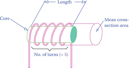
Figure 4.22
Definition of parameters in an inductor.
Example 4.3
The mean (average) diameter of a cylindrical 100 mm long winding of 500 turns is 10 mm. It has a high permeability core for which μ = 2.5 × 10⁻² H/m. Find its inductance.
Solution
The given values can be substituted in Equation 4.1 after conversion
Length l = 0.1 m
Cross section A = 1/4 × π × (10 ÷ 1000)2 = 0.785 × 10⁻⁴ m2
Example 4.4
The mean diameter of a cylindrical winding is 1 in, and its length is 2 in. If the winding has 300 turns, find the inductance of the winding. Winding has a steel core for which μ = 8.75 × 10⁻⁴ H/m.
Solution
Note that μ has a very small value. Also, pay attention to the fact that its value is in H/m (henry/meter). Thus, the dimensions of the winding must be converted to metric system. Finally, notice that the unit for μ is such that if multiplied by area and divided by length the resultant will be in henries.
The cross section and the length of the winding in metric system of units are
l = 2 ÷ 39.37 = 0.0508 m (1 in = 1 ÷ 39.37 m)
A = 1/4 × π × (1 ÷ 39.37)2 = 5.067 × 10⁻⁴ m2
From Equation 4.2
Permeability
Many electrical devices such as motors and transformers that we will discuss later have windings. The role of a winding is concentrating the magnetic effect of electricity. A winding is a wire in the form of a coil with many loops (turns).
Almost all windings, especially those in large sizes, have a metallic core. It is very important that this core be made from the category of metals that are ferromagnetic. Otherwise, the core has no or little effect. The ferromagnetic class of metals is those in the family of iron and steel that have magnetic effect (can be magnetized). Metals such as gold, copper, and aluminum have no such effect and in this respect cannot be used. The effect of a ferromagnetic core is to increase (by thousands of times) the magnetic lines generated by a winding when electric current passes through it. This property of a winding is called inductance. The more the inductance of a winding, the greater the magnetic effect.
This property of metals to enhance the magnetic effect is called permeability. Permeability of a core inside a winding directly affects the inductance of the winding. Permeability of different materials is compared to each other by relative permeability, which is a nondimensional number and specifies the permeability of various materials with respect to vacuum. Table 4.2 shows the relative permeability of some materials.
Table 4.2 Comparison of Permeability of Some Materials
| Material | Relative Permeability |
| Mu-metal (a highly magnetic alloy) | 20,000 |
| Permalloy | 8000 |
| Electrical steel (special steel for motors rotors, etc.) | 4000 |
| Regular steel | 100 |
| Nickel | 100–600 |
| Aluminum | 1.000022 |
| Platinum | 1.000265 |
| Wood | 1.00000043 |
| Air | 1.00000037 |
| Vacuum | 1 |
| Copper | 0.999994 |
| Superconductor | 0 |
4.11 Capacitance
Capacitance is a property of a capacitor. A capacitor can store energy, but “how much electricity can be stored in a capacitor?” depends on its capacitance. A capacitor stores energy in the form of an electric field (an inductor stores it in the form of a magnetic field). In other words, capacitance is a measure of the electric capacity of a capacitor.
Capacitance: Measurable property of a capacitor for storing electricity, measured in Farad.
Capacitor: Electric device mainly made of two conductors separated by an insulator. It has the property of storing electric energy in the form of an electric field. Energy stored in a capacitor can only be discharged instantly, not like a battery in which the stored energy can be gradually discharged.
The uppercase C is used to represent capacitance, and the unit of measurement for capacitance is farad (denoted by F). For instance, for a particular capacitor we may write C = 51 × 10–6 F. One farad is a large value, and usually its fractions are used instead, like 51 microfarad (51 μF).
Farad: Unit for measurement of capacitance of capacitors. Farad is a relatively large unit and fractions of it such as micro-farad and picofarad are commonly used.
Basically, a capacitor is made of two conducting surfaces (metals) separated by a layer of an insulated material between them (it could also be air or another gas). The capacitance of such a capacitor is directly proportional to the common area of the two surfaces and inversely proportional to the distance between them. Also, the insulator material adds its own effect because some materials are better insulators than the others. Thus, capacitance can be expressed by
| (4.3) |
where C is the capacitance in Farad, A is the shared area of the two conductors, and d is the distance between the surfaces of the two plates, as shown in Figure 4.23. The effect of the insulator is represented in k, called the dielectric constant of an insulator, the value of which also depends on the units of measurement (metric or imperial). The value of the constant k is measured in F/in or F/m. It can be seen that varying the common area by moving one plate with respect to the other changes the capacitance. This is used in the older radios, where a tuning knob was turned for selecting a station.
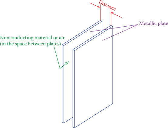
Figure 4.23
Basic parameters of a capacitor.
Table 4.3 Dielectric Constant of Air = k0 = 8.85 × 10⁻¹² F/m
| Material | k/k0 |
| Air | 1 |
| Liquid air | 1.5 |
| Glass | 3.8–14.5 |
| Nylon | 3.5–22.4 |
| Oil (cotton seed) | 3 |
| Oil (heavy oil) | 3 |
| Oil (mineral) | 2.1 |
| Paint | 5–8 |
| Paper (dry) | 2 |
| Porcelain | 5–7 |
| Quartz | 4.7–5 |
| Rubber | 2–4 |
| Rubber (hard) | 2.8 |
| Sand (dry) | 5 |
| Silicon | 11–12 |
| Soil (dry) | 2.4–2.9 |
| Tantalum oxide | 11.6 |
| Teflon | 2.1 |
| Water | 4–88 |
| Water (pure) | 88 |
| Wax (mineral) | 2.2–2.3 |
| Wood | 2–6 |
For various materials the constant k is defined in terms of the relative (to air) dielectric constant. For air this value is approximately
kair = 8.85 × 10⁻¹² F/m
Table 4.3 shows the relative dielectric constants for a number of selected materials.
Example 4.5
A capacitor is made up of two aluminum foils separated by a piece of paper, all three rolled together. The paper acts as an insulator between the aluminum sheets. In some capacitors the paper is wetted by oil for longer life. For dry paper (not oiled) the value of k is 0.356 × 10⁻¹² F/in. If the dimensions of the two aluminum foils are 1 inch wide and 10 inches long (before rolling), and the thickness of the paper is 0.002 inches, what is the capacitance of the capacitor?
Solution
All the values are given in imperial system. Thus, we may directly plug the values into Equation 4.3.
Recall from the conversion table in Chapter 1 that nano is the prefix in metric system for 10–9.
Example 4.6
In the metric system the constant in Equation 4.3 is 17.7 × 10⁻¹² F/m. If two plates each having an area of 25 × 250 mm2 are separated by a piece of dry paper 0.1 mm thick, what is the capacitance of the capacitor made out of these plates?
Solution
First, we need to convert the dimensions into meters. Thus,
d = 0.1 mm = 0.0001 m
A = 25 × 250 mm2 = 0.025 × 0.250 m2 = 0.00625 m2
F = 1.1 × 10⁻⁹ F = 1.1nF
4.12 Chapter Summary
- Electricity is the flow of electrons.
- For a continuous flow of electrons it is necessary to have a closed circuit.
- A pressure difference (potential difference), called electromotive force, is required to cause the flow of electrons in a circuit.
- Potential difference is also called voltage.
- Current is a measure of how many electrons move in one second. However, for measuring current a different unit, an ampere, is used.
- Electric current is not the speed of electrons in motion.
- All electric devices function based on one or more of the three main properties of electricity: thermal, magnetic, and chemical effects.
- Potential difference is measured in volts.
- Electric energy can exist in two forms: direct current and alternating current.
- In direct current the flow of electrons is always in the same direction.
- In alternating current, electrons continuously alter their direction of movement.
- Direction of current is a convention (arbitrarily selectable). In this book, the positive direction of current is considered to be from positive side to negative side (in a circuit). This is from higher voltage to the lower voltage.
- An electric circuit is made up of a source and some loads connected to the source. A source provides electricity and a load consumes electricity.
- In general, loads can be of three basic types: resistor, inductor, and capacitor. A resistor converts electric energy into heat. Inductors and capacitors store electric energy momentarily.
- A resistor has resistance, an inductor has inductance, and a capacitor has capacitance. Resistance, inductance, and capacitance can be calculated from their corresponding formulas. In physical circuits they can be measured.
- All wires have resistance and behave as resistors. Because in an electric circuit all parts are interconnected by wires, there is no electric circuit without resistance.
Review Questions
- What is electricity?
- What causes electric flow?
- How many types of electricity can you name?
- What is direct current electricity?
- What is alternative current electricity?
- What is alternating current electricity?
- What is the simplest electric circuit composed of?
- What is a source in an electric circuit?
- What are the basic components in any electric device or circuit?
- Does an electric circuit contain all the basic components? Explain.
- Describe resistance in an electric circuit.
- Describe a resistor.
- What is an inductor and what does it do to electricity?
- What is a capacitor and what role does it play in electricity?
- What is the physical form of an inductor? What is it made of?
- What is the construction of a simple capacitor? What are the parameters that determine the capacitance of a capacitor?
- What is voltage and what is the unit for measuring it?
- Using the analogy of water flow, what represents voltage?
- What is the unit for measuring electric current?
- Name the units of measure for resistance, inductance, and capacitance.
Problems
- A piece of copper wire is 40 ft long. If the resistance of this piece of wire is 0.2 Ω what is the resistance of a piece of the same wire that is 100 ft long?
- The resistance of a piece of wire is 1 Ω. The cross-section area of the metallic core of the wire is 0.05 mm2. What is the resistance of the same length of a wire of the same material, but with a cross-section area of 0.2 mm2?
- You have a 100 ft wire. The resistance of this wire is 1 Ω. You cut this wire from the middle and twist the two parts together along the entire length (so that you have 50 ft of double wire). What is the resistance of the double wire?
- In Problem 3, if you divide the 100 ft wire into four equal segments and wrap all four pieces together with their ends twisted together, what is the resistance of the quadruple wire?
- A coil has 500 turns and its inductance is 0.4 H. If you cut the coil from the middle length, so that each half has 250 turns, what is the inductance of each half coil?
- The coil in Problem 5 must be rewound so that it has half-length for the same wire. In this process the cross-section area increases by 10%. What is the new value for its inductance? Also, what is the change in its resistance?
- A winding with 400 turns has a steel core for which μ = 8.75 × 10⁻⁴ H/m. The mean cross section of the winding is 0.25 in2 and its inductance is 200 mH (millihenries). What is the length of the winding in mm?
- You put an 8 × 11.5 inch sheet of paper between two aluminum foils of the same size and roll them together to form an 8 inch height cylinder. Then you cut that into four pieces and solder two wires to each piece of aluminum foil in each piece. What is the capacitance of each homemade capacitor, if the paper thickness is 2 mil? (Hint: See Example 4.5.)
- What is the capacitance if in Problem 8 you use two sheets of paper between the aluminum foils?
- In Example 4.3, what is the resistance of the winding if it is made out of the wire in the Example 4.2?
- If the wire in Example 4.2 cracks and a gap of 0.01 mm is created between the two wire segments, what is the capacitance of the capacitor formed this way?