
9
Three-Phase Systems
OBJECTIVES: After studying this chapter, you will be able to
- Explain the difference and the similarity between single-phase and three-phase systems
- Explain the advantages of three-phase systems
- Understand why three-phase systems are more common in industry
- Extend the relationships in single-phase AC electricity to three-phase systems
- Understand delta and wye connections in three-phase electricity
- Describe the relationships and differences between wye and delta connections
- Make a distinction between balanced and unbalanced loads
- Calculate power and power factor in three-phase electricity
- Apply power factor correction for three-phase electricity
New terms: Balanced load, delta connection, Δ connection, inrush current, line current, line voltage, neutral line, null line, phase current, phase voltage, star connection, unbalanced load, wye connection, Y connection
9.1 Introduction
All over the world, except in very small local generators, commercial electricity is generated and distributed using a three-phase AC system. Three-phase electricity is, in fact, three single-phase AC systems integrated together. Obviously, this is because of advantages that a three-phase system has over three separate single-phase systems. Moreover, all three systems are generated simultaneously and by one machine. This makes the generation process more efficient. Similarly, on the consumption side, because of the same reasons many industrial loads such as electric motors can be made three phase, which makes them more efficient and even better (see Chapter 11) than equivalent single-phase loads. Except for certain relationships, all that we have learned so far about single-phase AC electricity applies to a three-phase electricity system. In this chapter we study the extension from single phase to three phase and the differences in formulation when it applies.
9.2 Three-Phase Electricity
In Figure 9.1 a single load connected to a source constitutes a simple circuit, as we have seen in previous chapters. The only difference is that the source is represented by a winding, because all generators have windings in them.

Figure 9.1
A single circuit consisting of a source and a load.
Figure 9.2 illustrates three of these assumed AC circuits near each other. Intentionally, the generators are shown forming a triangle, but at this time it is only a graphic layout. For ease of reference these systems are named A, B, and C. Supposing now that these three single-phase electric circuits are such that we can connect together the points that are near each other; that is, point A to B′, B to C′, and C to A′, as shown in Figure 9.3. If this can be done, then we may use only three wires for connection to the loads, instead of 6, provided that the loads permit this. This is shown in Figure 9.3, thus saving wire cost.
The arrangement on the right-hand side of Figure 9.3 can be rearranged to look as shown in Figure 9.4b, which is one of the ways a three-phase load can be connected to a three-phase source. The necessary condition to be able to connect the associated points in this circuit (A to B′, and so on) is that these points must have the same electric potential (the same voltage with respect to a reference) at any instant of time.
In Chapter 11 you learn about AC generators that work based on a magnetic field that rotates with respect to a winding. If there is one winding, the generated electricity is single phase. But, if there are three windings as shown in Figure 9.5, then the generated electricity is three phase. As

Figure 9.2
Three single-phase systems shown together.
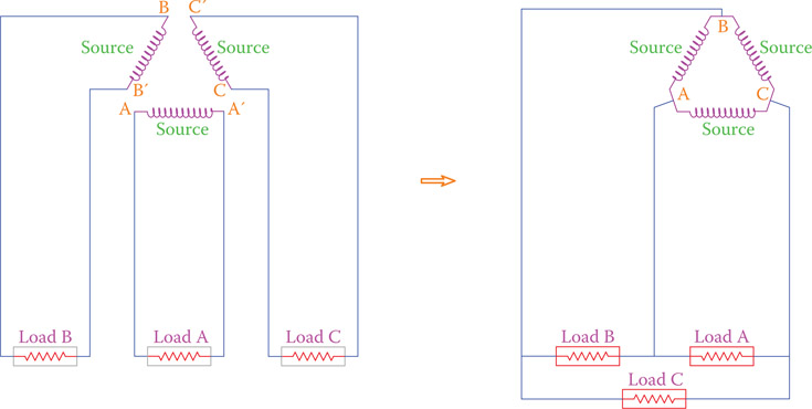
Figure 9.3
Saving in the number of wires used.
you see in Figure 9.5, the three windings are placed at 120° from each other. This causes a phase difference between the three voltages that are generated. The reason is obvious; one of the windings sees the magnetic field before the other two, and again the second winding sees it before the third, before everything is repeated. In other words, what happens to one winding in a given time happens to the other two windings with a delay that corresponds to 120° and 240° physical displacement. As a result of the rotation of the magnetic field, the generated voltage in each winding
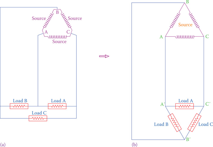
Figure 9.4
Common representation of a three-phase system. The three loads in (a) are shown as in (b).
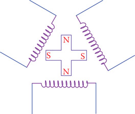
Figure 9.5
A simple representation of a three-phase generator, indicating the reason for phase difference between the voltages in the three windings.
has a sinusoidal form. For one cycle variation of the magnetic field the generated voltages in each winding are illustrated in Figure 9.6.
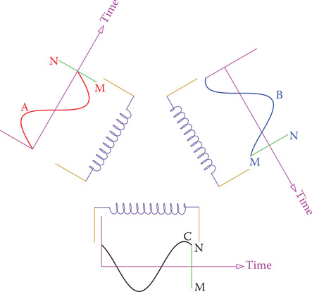
Figure 9.6
Individual waveform variation of the voltage in each winding for a one cycle period.
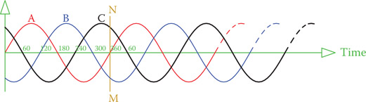
Figure 9.7
Waveforms of a three-phase system shown together on a common axis.
When put together, the three sinusoidal waveforms of a three-phase electricity system are shown in Figure 9.7. The three phases are addressed as phases A, B, and C, or phases 1, 2, and 3. No matter what the three phases are called, their order is very important and must be respected. Observe that in Figure 9.7 phase A reaches its maximum before B and C. B reaches its maximum after 120°, and phase C reaches its maximum 120° after B (240° after A). Also, notice that the vertical axis has no title because it can represent voltage or current. In Figure 9.7, line MN corresponds to the time for one full cycle and the variations of each phase are those shown in Figure 9.6.
9.3 Properties of a Three-Phase System
The fact that the three waveforms of a three-phase system are 120° apart gives desirable properties to it that makes it attractive from a practical viewpoint. The very first property of the voltages in three-phase electricity is that at each instant of time the sum of all the voltages is zero. This can be mathematically shown, but here we can observe that from the graphics in Figure 9.8 for only a few points.
At any instant, such as those marked by lines 1, 2, 3, and 4, one can verify by measurement on the figure that the sum of the values of the voltages of the three phases is zero. For example, at the instant denoted by line 1, the value of phase B is zero and the other two phases A and C have equal values but with opposite signs (A is positive and C is negative). This is true for any other instant of time. If the voltages of the three phases are denoted by VA, VB, and VC, then
| (9.1) |
The above fact leads to another way that the three voltage sources in a three-phase system can be connected together. This is shown in Figure 9.9. In this connection, one end of the three windings are connected together, and the voltage is taken from the other end. The common end can be used as a zero voltage reference point. This point is usually grounded, but there may also be a connection to this point, which is termed neutral line or null line. The neutral line goes to a similar point on the generation side.
Neutral line: Fourth line in a three-phase system, which ideally does not carry current and can be grounded; also called null line.
Null line: Same as neutral line in a three-phase system.
In a three-phase AC system at any instance the sum of the voltages in the three lines is zero. This is because these voltages are not in phase with each other.
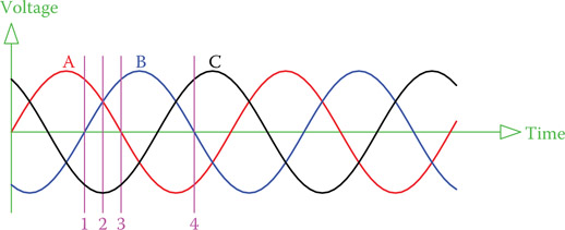
Figure 9.8
The sum of the voltages of the three phases are always zero.

Figure 9.9
Alternative connection method in three-phase electricity.
9.3.1 Wye Connection and Delta Connection
The former method of connecting the source voltages together is called delta connection (or Δ connection) because a Δ is formed. The latter form of connection is called Y connection (wye connection) or star connection. Note that in delta connection there are only three wires (there is no place for a fourth wire, but in Y-connection one can use three or four wires. The dashed (null) line in Figure 9.9 can be replaced by a short ground wire, which connects the common point to ground. It is also common practice to carry this wire while also grounding it, all depending on the case, as will be discussed in this chapter.
Delta connection: Way of connecting loads and sources to a three-phase system, where the components of a load or a source form a triangle (or delta, Δ) each corner of which is connected to the three lines.
Δ connection: Same as delta connection.
Y connection: Same as wye connection.
Wye connection: A way of connecting loads and sources to a three-phase system, where the components of a load or a source form a letter Y (that is one side of each component are tied together) and the free sides of the Y are connected to the three lines.
Star connection: Same as wye connection. One of the two ways for connection of loads and sources in a three-phase system.
Note the difference between the voltages in the two cases. At this time the connection to the source is in focus. In a delta connection the voltage generated in the generator winding is between each of the two lines, whereas in the wye connection the voltage between each line and the null line is equal to that generated in the winding.
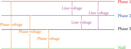
Figure 9.10
Definition of line voltage and phase voltage.
To distinguish the difference, the terms line voltage and phase voltage are employed. These definitions are depicted in Figure 9.10. When there are three lines carrying three-phase electricity, voltage between each two lines is called line-to-line or simply line voltage. In the presence of a fourth line the voltage between each line and the common point (or the null line) is called phase voltage. This is irrespective of how the connection is at the source.
Line voltage: Voltage between each pair of (three) lines bringing electricity to the loads in a three-phase system.
Phase voltage: Voltage between each line and the common reference point (neutral, which is normally grounded) in a three-phase system.
9.3.2 Voltage Relationships
Another property of three-phase electricity is the relationship between line voltage and phase voltage. Unless the voltages are disturbed by various load conditions, line voltages for all three phases are the same. Also, all the three phases have the same phase voltages. Similar to the single-phase electricity, line voltage and phase voltage express the effective values of the voltages, unless mentioned otherwise. If line voltage is denoted by VL and the phase voltage is represented by VP, then
| (9.2) |
Example 9.1
Voltage across each winding of a generator when working is 120 V. Find the line voltage and the phase voltage for the circuit connected to this generator (1) when the generator windings are delta connected and (2) when the windings are wye connected.
Solution
- Delta connection: Because the voltage across each winding is 120 V, then the line voltage is 120 V. The phase voltage thus can be found from Equation 9.2 as
- Y connection: In this case for each phase, voltage between the two ends of its winding is 120 V. Thus, the phase voltage is 120 V.
The line voltage is determined from Equation 9.2 as
Note that, as this example shows, depending on how the wires are connected together at the source, the voltages can be different. This becomes very important when connecting a source and a load to a circuit. Often, the windings in a load are not initially connected. There are six terminals for either a three-phase source or a three-phase load (two terminals for the two ends of each winding). A technician must connect these together in the correct way for the desired connection.
In expressing the voltage in three-phase electricity, in order to make it clear that nobody doubts whether the given value is for the line voltage or the phase voltage, it is common to state both values. This is particularly done for standard voltage values. For example, in expressions like 120/208 V line and 220/380 line there is no doubt that the larger value is for the line voltage.
A three-phase source or load has six terminals. They must be connected together in the correct way to form delta connection, or wye connection, as desired.
9.4 Load Connection in Three-Phase Systems
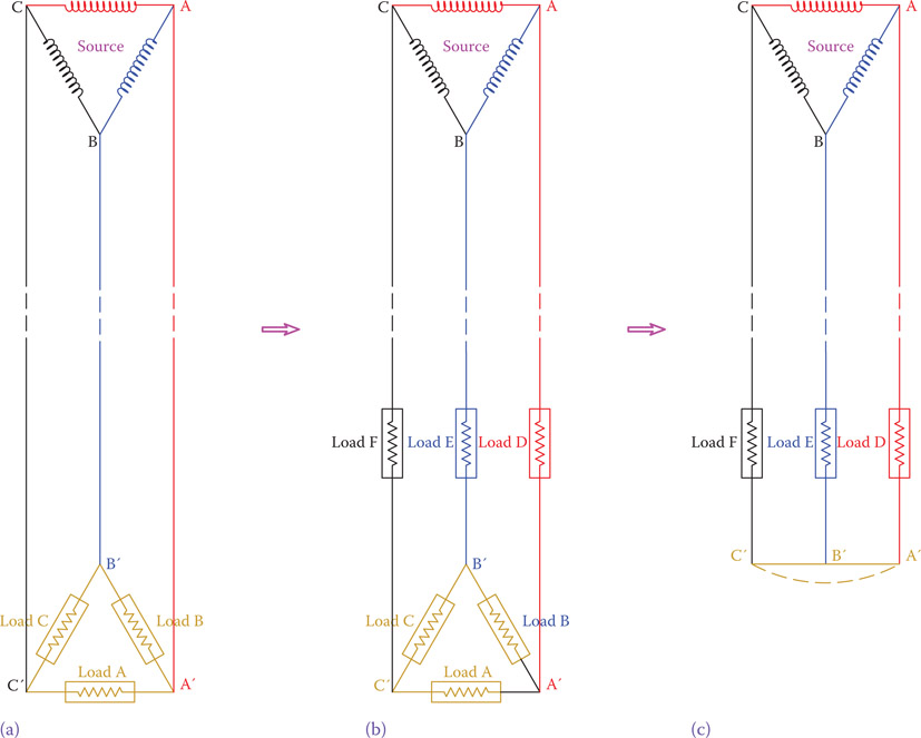
Figure 9.11
Connection of load to a three-phase system. (a) Three loads connected in delta form. (b) Three other loads can be added to the circuit. Then loads A, B, and C can have little or zero voltage across them. (c) Loads A, B, and C can be removed and points A′, B′, and C′ can be put together; thus, wye connection.
As it was previously mentioned, a three-phase system is like three single-phase systems. In this sense the loads connected to three-phase electricity can be (and in many cases are, as we will see) independent single-phase loads. At this time, suppose that there are three similar loads connected to the three lines of a three-phase system, as shown in Figure 9.11a. Note that the source is shown with delta connection, but it could have a wye connection, too. The difference would have been in the line voltage received by the loads.
Current flows from the source to the loads and while the instantaneous direction and magnitudes of the currents in the three lines are not the same, their effective magnitudes are equal, because the loads are assumed to be similar.
Now suppose that three other similar loads are added to this circuit, as illustrated in Figure 9.11b. These new loads reduce the current in the three lines, thus reducing the voltages at points A′, B′, and C′. If these loads are large enough, then the voltage values at points A′, B′, and C′ can be so small that without overloading the circuit we may completely remove the three former loads and just connect these three points together, as shown in Figure 9.11c. The result, as can be observed in Figure 9.11c, is that the loads of a three-phase system can be connected by employing either delta connection, or wye connection. This is particularly true for three-phase loads that consist of three simultaneous similar sets of single loads.
On the basis of the above discussion, because connection at the source can be either delta or wye, and at the load can also be either delta or wye, there are four possible ways of connecting sources and loads in a three-phase circuit. These are depicted in Figures 9.12 and 9.13.
In delta connection the ends of each (load or source) element are connected together, such that they form a triangle. Then the three corners of the triangle are connected to the three electricity lines.
In wye connection one end of all the (load or source) elements are connected together; this point may be grounded. The other ends are connected to the electricity lines. A letter Y is formed by the elements.
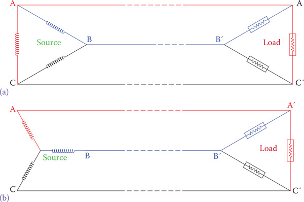
Figure 9.12
(a) Source and load are both delta connected and (b) source is wye connected and load is delta connected.
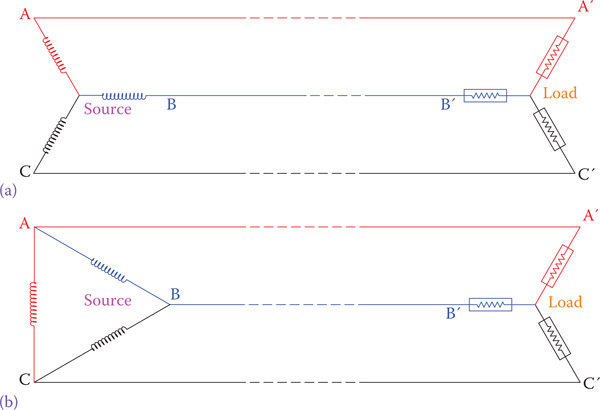
Figure 9.13
(a) Source and load are both wye connected and (b) source is delta connected and load is wye connected.
9.4.1 Balanced Loads and Unbalanced Loads
Similar to what we have already seen in Chapter 8 for the type of loads in single-phase electricity, the loads connected to a three-phase source can contain resistive, inductive, and capacitive components. No matter whichever component is present and if they are in series or parallel, if all the three loads connected to a three-phase circuit are exactly similar in arrangement and magnitudes, then the load is said to be balanced and to the three-phase circuit they form a balanced load.
Balanced load: Three identical loads in a three-phase system that come together as a three-phase load.
With the exception of three-phase loads (see Section 9.5) it is extremely difficult if not impossible to arrange all the independent loads connected to a three-phase circuit to be exactly identical. For example, in the electricity distribution in cities the generated power is three-phase; however, the electricity coming to individual houses is single phase. Each group of houses is fed by one phase of the three-phase electricity. Because the electricity consumption of each house is independent of others, there is no way to have a balanced load.
For a balanced load the currents in the three lines are exactly equal (the three lines have the same current magnitude and power factor). Moreover, if there is a 4th line, the current in this line is zero. This is not the case for unbalanced loads.
Unbalanced load: When in a three-phase system, the load consists of three separate and not identical single-phase devices.
When connecting loads to a three-phase circuit, normally, we are not concerned of how the connection at source is (delta or wye). The concern is about the line voltage and phase voltage that determine the appropriate connection for a load. More often, there are three lines that constitute the three phases of a three-phase circuit. The voltage between each pair is the line voltage. A load is connected either in delta or in wye, as depicted in Figure 9.14. If a wye connection is employed, the common point is usually grounded. This helps for protection and fault detection.

Figure 9.14
Delta and wye connection of a load to a three-phase circuit.
The voltage across each individual load is the phase voltage. If a wye connection is employed, phase voltage implies the voltage between each line and the common (grounded) point, but for a delta connection the phase voltage and the line voltage are the same. The definitions for line and phase voltages are also shown in Figure 9.15.
Example 9.2
If the line voltage in Figure 9.14 is 200 V, what is the voltage applied to each load element (1) when delta connection is used and (2) when the loads are wye connected to the line?

Figure 9.15
Definition of phase current and line current.
- In this case the whole line voltage is applied to each load element. Thus, the voltage across the element is 200 V.
- In this case the 200 V line voltage is distributed between two elements. The relationship in Equation 9.2 again applies, and hence the voltage across each element is
A three-phase load is a balanced load.
9.4.2 Line Current and Phase Current
In conjunction with phase and line voltage terms, we also have phase current and line current. Line current is the current that one can measure in each of the phase lines to which loads are connected. Phase current is the current passing through the load. For two sets of loads, one with delta connection and one with wye connection, these currents are illustrated, also, in Figure 9.15, where the circle with a letter “A” inside implies an ammeter.
Phase current: Current inside each electric component connected to a three-phase system, as opposed to the line current representing the current in the lines carrying electricity to that component.
Line current (in three-phase systems): Current in lines bringing electricity to the loads in a three-phase system.
9.5 Three-Phase Loads
A three-phase load is a set of three exactly similar combinations of electric components arranged in exactly the same way (in series, parallel or other). The reason to have three-phase loads is the higher power demand. For instance, in industry the majority of motors are three phase, particularly the larger motors that deliver large magnitudes of power to conveyors, pumps, blowers, machine tools, and so on. As studied before, the three components in AC are resistors, inductors, and capacitors. In this sense, the three-phase loads can be purely resistive (consisting of heating elements only), resistive and inductive (like electric motors), and resistive, inductive, and capacitive (like many motors that are accompanied by capacitors for various reasons).
Because the three separate sets of loads are identical and are simultaneously connected to electricity, they are balanced. Thus, all three-phase loads automatically form a balanced load for a three-phase circuit.
Dealing with three-phase loads is much simpler than if independent single-phase loads are connected to a three-phase circuit. In fact, many of the relationships and calculations for three-phase loads resemble their counterparts for single-phase systems. This is because the individual parts of the loads on the three phases behave alike. For instance, in a load consisting of resistors and inductors, as we have seen before, there is a phase difference between the current and the voltage (see Chapter 8). For a three-phase load this phase difference is the same for all the three phases, and, as a result, we need to find it for only one phase.

Figure 9.16
Wye and delta connection of the same load.
Analyzing three-phase loads is tackling the same sort of problems that we have seen in Chapter 8. Therefore, we need to know the relationships between voltage, impedance, current, power, and power factor, as well as power factor correction. Again, here we have three types of power: active power, reactive power, and apparent power. We need, though, to make a distinction between delta connection and wye connection. A three-phase load can initially be open, with six terminals to deal with. On the basis of how these terminals are connected together and to the external lines they form a wye or a delta connection. Figure 9.16 shows how the 6 terminals A, B, C, A′, B′, and C′ can be connected for wye and delta connection. The two methods of connection are not equivalent and affect the current and power taken from a circuit (see Section 9.5.1).
Dealing with unbalanced loads is more difficult, and each branch must be individually analyzed and the results be put together.
9.5.1 Three-Phase Relationships for Balanced Loads
Referring to Figure 9.15, which depicts the definition of line and phase currents as well as line and phase voltages for both delta and wye connection of a load, the following relationships always exist:
For wye-connected load,
| (9.3) |
| (9.4) |
| (9.5) |
| (9.6) |
Current in a component can always be found by Ohm’s law. If the impedance of each of the three elements of a three-phase load is denoted by Z, then
| (9.7) |
Equations 9.3 to 9.7 can determine all values if two of them are known.
Note that for a balanced load all the phase currents are equal and all the line currents are also equal. Also, referring to Figure 9.17, although the line currents are equal in magnitude, they cannot be in phase with each other. As shown, for both the delta-connected load and the wye-connected load, at a given instant while the currents on two phases are toward the load, the current on the third phase is in the opposite direction (remember that in AC electricity the current direction continuously changes; here the direction for current implies that if at a given instant its magnitude is positive or negative). Because the AC current continuously changes direction, those shown in Figure 9.17 are momentary values and for one instant later the directions will be different. We want to say that for a balanced load the three currents have the same relationships as the voltages have. That is, for sinusoidal voltage the variation of currents is sinusoidal and with a phase difference, as shown in Figure 9.7, and moreover, their instantaneous sum is zero.
| (9.8) |
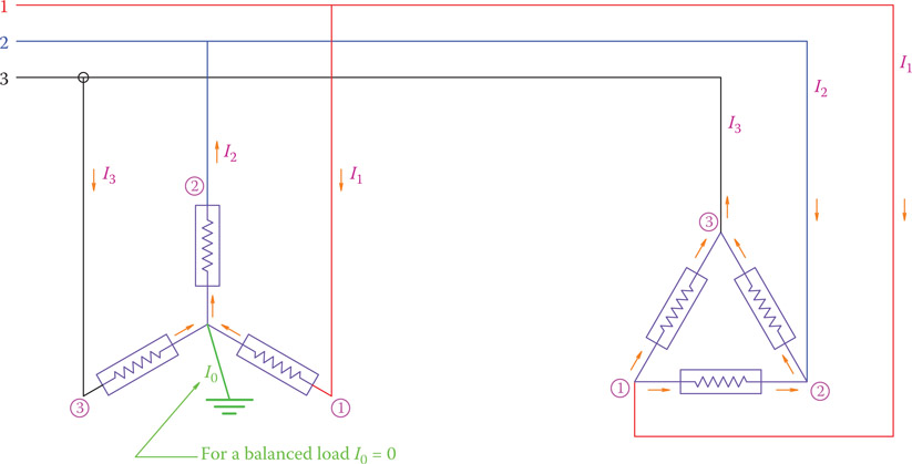
Figure 9.17
Instantaneous direction of currents in three-phase systems.
Equation 9.8 implies that at any instant the sum of the currents in the three lines of a three-phase system is zero for balanced loads. In this sense, current I0, associated with the grounded wire or the neutral line (when it is present) is zero. This is the reason why the neutral line is smaller in size than the three phase lines.
For wye connection,
Line current = phase current
Line voltage = Phase voltage
For delta connection,
Line voltage = Phase voltage
Line current = Phase current
Example 9.3
A three-phase heater consists of three elements each having 20 Ω resistance. (1) If the heater is connected to 220/380 V line (that is, line voltage is 380 V) using delta connection, what is the current in each element? (2) What is the current in the lines bringing in the three-phase electricity? (3) Also, find the heating power of the device in kW.
Solution
- When delta-connected, each element is subject to the line voltage of 380 V, as the line voltage and phase voltage are the same in this case. Since we are dealing with heating elements, all the loads are resistors. Thus,
- The line current based on Equation 9.6 is
- The heating power depends on the power consumption of the resistive elements. This can be found by any of the power formulae in Chapter 7. Because there are three elements, the power in one can be multiplied by 3.
Power = (3)(380)(19) = 21,660 W
Compare the line current and the power for the heater in Example 9.3 if it is wye connected to the same three-phase electricity.
Solution
In this case it follows from Equation 9.4 that
And from Equation 9.3,
IL = IPh = 11 A
Power = (3)(219.4)(11) = 7220.23 W
This example clearly shows that in this case the power is 3 times smaller than in the previous case.
Example 9.5
If in the problem of Example 9.3 one of the phases is disconnected by a fault, determine the currents in the other two lines and what the power is.
Solution
Refer to Figure 9.15 with the delta connection and suppose that one of the lines does not exist. In such a case we have two parallel single-phase loads connected to 380 V electricity. One of the parallel branches has a 20 Ω resistor, and the other one has two 20 Ω resistors in series (40 Ω). All the loads are resistive, and the current in the connecting lines is
The power is found by adding the individual powers in the two parallel branches
P = (20)(19)2 + (40)(9.5)2 = 10,830 W
which also could be found from
P = (380)(28.5) = 10,830 W
If in the problem of Example 9.4 (wye-connected load) one of the wires is broken by an incident, determine the current in the remaining lines and the power supplied.
Solution
In the same manner that Example 9.5 was tackled, if one line is disconnected, we study the circuit of the remaining single-phase system. For this example the remaining circuit consists of 40 Ω resistor connected to 380 V. The current and power, therefore, are
P = (380)(9.5) = 3610 W
Example 9.7
Figure 9.18 shows three identical coils that in series with three resistors are connected to a three-phase system. The line is 220/380 V and the frequency is 60 Hz. The resistors are 40 Ω each. The resistance of each coil is 4 Ω, and its inductance is 100 mH. Determine the current in the line and the power factor for this load.
Solution

Figure 9.18
Circuit of Example 9.7.
Figure 9.18 shows that the load is wired for delta connection. Each coil is equivalent to a resistor and an inductor in series. The resistance of each individual load, thus, is 44 Ω. For each phase,
This power factor is the same for all loads, and therefore it represents the power factor of the three-phase load.
9.5.2 Power in Three-Phase Electricity
The relationships for power for three-phase systems must be separately stated. There are two aspects of power relationships, one is with regards to the three types of power (active, reactive, and apparent), and the other is with regards to the fact that we have phase voltage and phase current versus line voltage and line current. The relationships between active, reactive, and apparent power are the same that we have seen before (see Chapter 8), that is
| (9.9) |
| (9.10) |
| (9.11) |
But, then the expression for apparent power S for both delta connection and wye connection of a load is
| (9.12) |
or
| (9.13) |
The two expressions in Equations 9.12 and 9.13 are equivalent because in delta connection, where the phase and line voltage are the same, the line current is times the phase current and in wye connection that the line current and the phase current are the same the line voltage is times the phase voltage.
Equations 9.12 and 9.13 must be used together with Equations 9.10 and 9.11 in order to avoid any confusion when a load is entirely resistive or entirely reactive. When a load is entirely resistive, the power factor is 1 and the apparent power and active power are the same. Likewise, when a load is entirely reactive, for instance, when a set of capacitors are connected to a line, the power factor is zero and the apparent power and the reactive power are the same.
Example 9.8
For the load in Example 9.7, determine the active, reactive, and apparent powers.
Solution
As shown in Figure 9.18, the line voltage is 380 V, which is also the phase voltage for the load, because it is delta connected. We find the apparent power by both Equations 9.12 and 9.13 in order to show that both must lead to the same answer. The line and phase currents have been found in Example 9.7 to be 11.36 and 6.56 A, respectively.
S = (3)(380)(6.56) = 7478 VA
Note that the difference is because of the round-off error. Active and reactive powers are then found from Equations 9.10 and 9.11.
P = S × pf = (7477)(0.76) = 5682 W
Example 9.9
A small three-phase generator provides power to a three-phase oven. The resistors in the oven are 100 Ω each. The line voltage is 173 V. If the windings in the generator are delta connected, find the current in the generator winding (1) when the heating elements are connected in delta and (2) when they are connected in wye.
Solution
The arrangement is shown in Figure 9.19. This problem is simplified in order to demonstrate the relationships between the values of the currents due to altering the way a load is connected to a source.
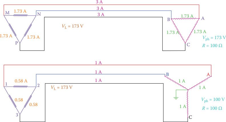
Figure 9.19
Circuit of Example 9.9.
-
When both the load and the source are connected in the same way, the currents in the source winding are the same as the current in the load branches. For this example,
(using Equation 9.12)
On the generator side
-
If the load is wye connected,
(using Equation 9.12)
and on the generator side
All the results are shown in Figure 9.19.
9.5.3 Power Factor Correction for Three-Phase Circuits
In the same way that for single-phase electricity the power factor can be improved by adding appropriate capacitive load in parallel with other loads, in three-phase electricity a bank of capacitors can be added for power factor correction. Like any other three-phase load, the capacitors can be wye connected or delta connected, as shown in Figure 9.20. The principle of determining the capacitor size and the procedure is the same as discussed in Chapter 8 (see Section 8.14). Because this task is performed for balanced loads, the necessary calculations can be based on the information for one phase.
In what follows we see examples of power factor improvement, which depict the details of the necessary work.
Example 9.10
A three-phase load takes 10 A if delta connected to 120/208 V, 60 Hz electricity. If the power factor for this load is 66 percent, find the size of a set of capacitors, delta connected, to improve the power factor to 95 percent.
Solution
The line current is 10 A in each of the three wires. Because both the load and the capacitors are delta connected, there is a one-to-one relationship between the elements. We may directly work with the given current.
A part of the 10 A current goes toward the active power and part corresponds to the reactive power:
Current corresponding to the active power = (10) (0.66) = 6.6 A
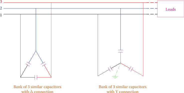
Figure 9.20
Connection of capacitors for power factor correction.
When capacitors are added, the part of the current for the active power does not change and is still 6.6 A. But the part corresponding to the reactive component(s) changes and so does the total current (not 10 A anymore, but smaller). We need to find the difference between the two values of the old and new current for reactive power. That is the current for the capacitor(s).
New line current after capacitors are added
New current corresponding to the reactive load
Difference between the old current and new current for reactive power = 7.5 − 2.15 = 5.35 A
Current in the line due to the capacitors = 5.35 A
On the basis of the voltage, the current due to a capacitor, and the frequency we may find the capacitance.
Note that not any 68 μF capacitor can be employed. The capacitors must be rated for more than 208 V, say 250 V.
Example 9.11
The power factor of a 12 kW three-phase load is 0.75 inductive (or lagging). Find the capacitance of a set of wye-connected capacitors to raise the power factor to 0.92. The line voltage and frequency are 400 V and 50 Hz, respectively.
Solution
In this problem, because we have the active power (kW), we base all the calculations on the power values. With a power factor of 0.75, the apparent and reactive powers are
After the power factor is improved, the new apparent power is
The difference between the new reactive power and the previous value is due to the reactive power of the capacitors. Thus, the size of the capacitors can be found from the relationship for capacitor power and three-phase power (see Section 8.7).
QCap = 10.58 − 5.11 = 5.47 kVAR
Because the capacitors are to be wye connected, the voltage across each capacitor is V. This voltage gives rise to a phase current (also line current) of , where XC is the reactance for each capacitor. It follows from Equation 9.12 that
from which XC can be determined. Thus,
and the capacitor size is
Capacitors with the above capacitance may not exist. In such a case the nearest standard value capacitor that is available must be used or it might be arranged by combination; the selected capacitor must have the rating for 231 V (). An available choice is a 120 μF, 450 V capacitor.
Example 9.12
A three-phase 12 kW motor connected to 400 V and 50 Hz line has a power factor of 0.75. Find the new power factor if a bank of three 100 μF capacitors is connected to the same line (1) when the capacitors are delta connected and (2) when they are wye connected.
Solution
A motor always introduces a lagging power factor in an AC circuit. When capacitors are connected to the same line, they introduce capacitive reactive power to the line. The effect of capacitors is to reduce/cancel the inductive effect of the motors. For this problem we find the (reactive) power introduced to the line and subtract it from the initial reactive power. The difference defines the new reactive power for the circuit.
-
Delta connection
For 50 Hz each capacitor reactance is
Find power of the capacitor bank:
Find the apparent power of the circuit before capacitors are entered:
New reactive power (after capacitors are added) = 10,583 − 15,000 = −4417 VAR
New apparent power = 12,783 VA
New power factor (for delta connection) (leading power factor)
-
Wye connection
The same procedure must be repeated for wye connection. Certain variables do not change, and the calculation does not need repetition. Thus,
XC = 31.8 Ω, Initial reactive power = 10,583 VAR.
Find power of the capacitor bank (for wye connection):
(Note the important fact that the power this time is 3 times smaller than when the capacitors were delta connected.)
Find the new reactive power of the circuit after capacitors are added:
New reactive power = 10,583 − 5000 = 5583 VAR
Pay attention to the fact that, though the values of the power factor in the two cases are very near, there is a big difference between the two cases. When the capacitors are delta connected, the resulting circuit is capacitive and the current is leading the voltage, but when they are wye connected, the circuit is still inductive and the current is lagging the voltage. In the first case if a larger capacitor is selected, it has an inverse effect of reducing the power factor, whereas in the second case a larger capacitor improves the power factor further.
9.5.4 Star-Delta Switch
The above example shows a number of facts that in practical applications use is made of them. These are
- For the same load, the current in the line and the power consumption are smaller (one third, to be more specific) if the load is connected in wye rather than delta.
- By the same token, a generator can deliver more power if the windings are delta connected.
For the above reasons, in order to reduce the initial current of certain applications, particularly three-phase electric motors that have a high inrush current, a special type of switch is used that connects a three-phase load to electricity in two stages. In the first stage a wye connection is made by a first turn of the switch, and with a further turn the connection is changed to delta. This arrangement is schematically illustrated in Figure 9.21. First, points R, S, and T, which are the free ends of the load (winding) are connected to A′, B′, and C′. This makes a wye connection, but if R, S, and T are connected to A, B, and C (i.e., what is done after a further turning of the switch), then the load is delta connected to the three-phase line.
Inrush current: Relatively high current that a motor initially experiences when connected to electricity (at zero speed). Current decreases as the motor speeds up.
A star-delta switch, however, is a mechanical system, and it belongs to the technology of the past. Nowadays, this technology is replaced with electronic switching; instead, for starting motors a variable frequency drive (VFD) is employed, which also offers other advantages. A variable frequency drive is based on AC-to-DC and DC-to-AC conversion, discussed in Chapter 20, which can also be regarded as a frequency converter. With such a device the frequency of AC electricity can be varied. Hence, as we discuss in Chapter 11, the rotational speed of a motor, which depends on the line frequency, can be altered. Furthermore, because this is an electronic device, it can be used for soft starting of a motor by limiting the current. Thus, it provides the same advantage as the star-delta switch. VFDs come in various capacities (e.g., for driving a 0.5 hp motor or a 500 hp motor). They must be capable of handling the required power by a motor; hence, their physical size depends on the power that they can provide to a motor. A very small example of such a device is shown in Figure 9.22.

Figure 9.21
Schematic of a star-delta switch for starting three-phase motors.

Figure 9.22
Example of a small variable frequency drive.
9.6 Use of Vectors in Three-Phase Electricity
We have already seen that using vectors could help tackle AC problems, displaying phase relationships, and make it easier. In the same fashion, in three-phase systems, using vectors greatly facilitates finding line currents and the phase angles for different loads. Moreover, the relationship between the line voltage (current) and phase voltage (current) and why one is times the other are more clearly demonstrated by the use of vectors.
Figure 9.23 depicts three vectors denoting the three voltages in a three-phase system, which are 120° out of phase with each other. These could be the line voltages or the phase voltages. Note that the vectors shown clearly satisfy the principal relationship in Equation 9.1; that is, if they are added together their vector sum is zero. All other voltage or current values can be shown on the same graph. In this way the phase difference between variables will be graphically shown.
Figure 9.24a shows the windings of a three-phase generator with wye connection, which allows defining a reference point for measuring voltages. The three-phase voltages are called VA, VB, and VC, respectively. Also, the three line voltages are identified as V1, V2, and V3, as shown. The line voltages are obtained from the phase voltages as follows:
| (9.14) |
VA, VB, and VC are shown in Figure 9.24b, with arbitrarily and intentionally showing VA along a horizontal line; VB and VC, are then at 120° and 240°, respectively, lagging VA.
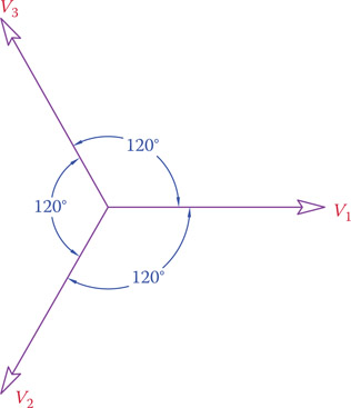
Figure 9.23
Representation of the three voltages in a three-phase system.
Figure 9.24b also shows the formation of V1 from VA and VB, It shows clearly the value and phase relationship between VA and V1. In the same way, V2 and V3 can be obtained (the details are repeats of the same process as for V1 and are not shown). Figure 9.24b clearly shows that each line voltage is 30° leading its corresponding phase voltage, and it is larger by a ratio of . (The length ratio can be depicted by trigonometry relations, but it is not shown here.)
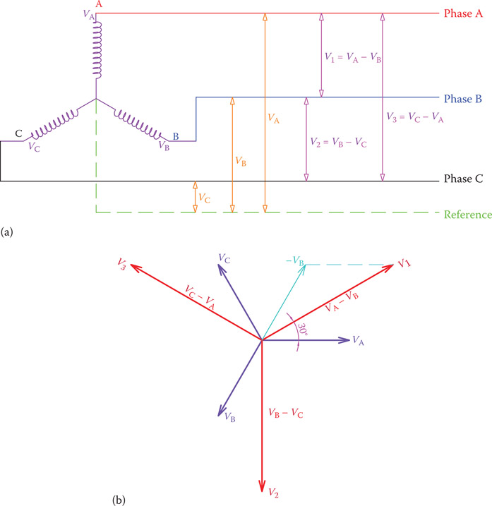
Figure 9.24
Vector representation of voltages in three-phase system. (a) A three-phase system. (b) Its phasor diagram for voltages and currents.
The same graph as in Figure 9.24b is repeated with a different notation in Figure 9.25a and b. The purpose is to indicate that as far as the length relationships and the angle relationships are clearly shown, the vector representation can be as in Figure 9.25a. The fact that the corresponding vectors for line voltages appear in the form of a triangle has nothing to do with delta and wye connection methods. The line voltages in Figure 9.24b can equally be shown as in Figure 9.25a, with no fault. The vectors for line voltages must indicate that
- They are 120° out of phase with each other.
- They have 30° phase difference with phase voltages.
- They are times in length compared to phase voltages.
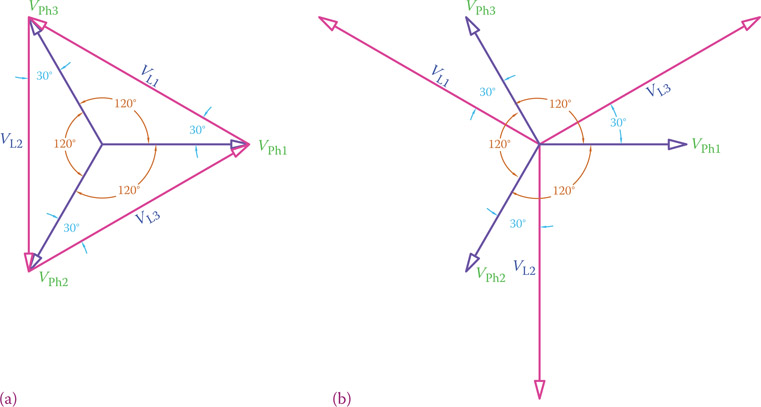
Figure 9.25
Phase and line voltages relationships. Either (a) or (b) can be used. Both show the 30° phase difference between line voltage and phase voltage.
On the basis of the above mentioned vector representation, three vectors for currents can also be shown on the same graph. Depending on the type of load (if resistive, inductive or so on) and the way they are connected, they can be in phase or out of phase with line voltages and phase voltages. It all depends on the loads, their values, and how they are connected. This is more clearly exhibited by an illustrative example. For a balanced load all the current vectors are equal and all the phase angles for the three phases are the same.
Example 9.13
A three-phase load consists of three identical elements. Each element (for each phase) consists of an inductor and a resistor in series. The load is wye connected and VL = 440 V. If R = 3 Ω and XL = 4 Ω, find the current in the elements, the voltages across each resistor and across each inductor.
Solution
For VL = 440 V the phase voltage (across the element) is 440/1.73 or 254 V. Also, the impedance for each element is
and the (line or phase) current is
254 ÷ 5 = 50.8 A
The voltages across the resistor and the inductor are, respectively,
VRes = 3 × 50.8 = 152.4 V
VInd = 4 × 50.8 = 203.2 V
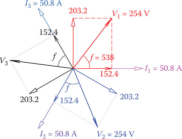
Figure 9.26
Phasor diagram showing the vector relationships between voltages and currents.
The phase angle for this load is 53° (e.g., from R/Z), and as usual for inductive load the current is lagging the voltage. Figure 9.26 shows the various vectors corresponding to the currents and voltages in this example. The graph shown in Figure 9.26 is called the phasor diagram for the circuit and graphically shows the size and phase relationships for various voltages and currents. Because the load is balanced in this case, everything is repeated three times but also rotated 120°. The process is similar to what we have already seen for single-phase AC electricity. Note that the voltage across the resistor is in phase with the current and the voltage across the inductor leads the current by 90°, resulting in a 53° phase difference between the current and the voltage. Also, note that the vector sum of the three currents I1, I2, and I3 is zero, thus conforming to Equation 9.8, as it is for the voltages V1, V2, and V3.
If there were capacitors in the circuit, the treatment would be exactly the same, bearing in mind that their effect is the opposite of that of the inductors and that they influence the phase angles. Also, resonance can occur (see Section 8.13).
9.6.1 Current Relationships
Similar to the way various voltages (three-line voltages and three-phase voltages) could be represented by vectors, various currents can also be shown as vectors. In this way their relationships can be graphically illustrated. For balanced loads all the line currents are similar and all phase currents are also similar. The magnitude and phase relationships are also the same for all three phases, and, therefore, calculations can be carried out for one phase and generalized for other phases. This, nevertheless, is not true for unbalanced loads. For unbalanced loads, finding the magnitudes and phase relationships for currents cannot be done without the use of vectors.
Figure 9.27 shows the line and phase currents for a delta-connected load. Whereas formerly we considered only two currents, namely, the line current and phase current, here we need to distinguish these two currents for the three phases. For this reason, as shown in Figure 9.27, the line currents are called I1, I2, and I3, while the phase currents are named IA, IB, and IC (similar to what was done for the associated voltages). The graphs shown correspond to a balanced load and, as can be seen, in the same way that there is a phase difference of 30° between line voltages and phase voltages when they are not the same (i.e., for wye connection), there is a 30° phase difference between line currents and phase currents in delta connection (i.e., when they are not the same. In wye connection these currents are the same).

Figure 9.27
General relationships between phase and line currents in delta connection. (a) Phase and line currents. (b) Line currents in terms of phase currents.
In Figure 9.27, three-phase currents are shown equal to each other, corresponding to a balanced load. In general, the three currents of each phase can be different. The relationships between three-line currents and three-phase currents, as shown in Figure 9.27, are as follows
| (9.15) |
Figure 9.27b shows the details of vectors for I1. The relationships in Equations 9.15 can be used to find the line currents if the phase currents are known and vice versa. It provides also the general method for tackling problems with unbalanced loads.
9.7 Unbalanced Loads
Many loads in a three-phase system can consist of individual single-phase loads connected between the neutral line and one of the phase lines. In general, a single-phase load can be connected to two phase lines, but this is less likely to happen in practice. The best example is the distribution of electricity in cities. Almost all the houses receive single-phase electricity because there is no need for three phases and all the domestic appliances are single-phase loads. This is schematically shown in Figure 9.28 for 220/380 V systems. (For distribution in North America, see Section 12.2.)

Figure 9.28
Electricity distribution in cities from a three-phase system.
For an unbalanced load the individual currents for each phase must be found as for a single phase. This gives the values for phase currents. If the loads are wye connected (in the majority of cases), these individual values define the currents in the three-phase wires. The neutral wire in such a case may carry a nonzero current that can be determined by the vector sum of the calculated currents.
In the rare case of having unbalanced loads connected in delta the relationships in Equations 9.15 can be employed.
The following examples help to better understand the cases for unbalanced loads.
Example 9.14
In a three-phase, four-wire system the line voltage is 415 V and the resistive loads of 10, 8, and 5 kW are connected in Y. Calculate the line currents.
Solution
In this example the loads are all resistive. So, there is no phase difference, but the load values are different. First, we find the phase voltage:
VPh = 415 ÷ 1.73 = 240 V
and the three-phase currents are
IA = 10 × 1000 ÷ 240 = 41.67 A
IB = 8 × 1000 ÷ 240 = 33.33 A
IC = 5 × 1000 ÷ 240 = 20.83 A
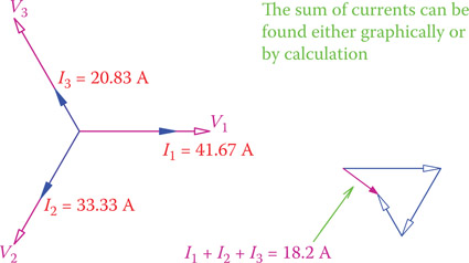
Figure 9.29
Solution of Example 9.14.
The above values are already for line currents because of wye connection. What is important here to notice is the current in the neutral line, which is not zero because the loads are not balanced. This current can be found from the (vector) sum of the three line currents. Figure 9.29 shows the sum of the calculated currents and the nonzero current of the neutral line.
From the above values of the line currents the neutral line current can be found (by using a graphics method or by calculation) to be 18.2 A.
Example 9.15
Three different single-phase loads are connected in delta (each one between two phase lines) across a 480 V, 60 Hz three-phase line. Determine the line current and show the current and voltage in the vector form (phasor diagram). The loads are as follows:
- Load 1: 24 kW, with pf = 1 (phase angle = 0, just active power)
- Load 2: 24 kVA, with pf = 0, lagging (current lags voltage, inductive load)
- Load 3: 24 kVA, with pf = 0.5, lagging (current lags voltage, more inductive than capacitive load, as well as resistive load).
Solution
Power magnitude for all the three loads is 24, but the loads are of different nature. Thus, the currents are equal in magnitude, but each one has a phase difference with its respective voltage. If, as in Figure 9.26, the phase currents are denoted by I1, I2, and I3 and the line currents are represented by IA, IB, and IC then
IA = 24 × 1000 ÷ 480 = 50 A
IB = 24 × 1000 ÷ 480 = 50 A
IC = 24 × 1000 ÷ 480 = 50 A
These are the currents in the loads. A power factor of 0 for the second load implies a 90° lagging phase difference and a power factor of 0.5 for the third load implies a 60° (cos–1 0.5 = 60°), also lagging, phase difference. The first load has no phase difference.
Figure 9.30b illustrates the three phase currents with respect to the three voltages (implying their respective phase differences). Figure 9.30c shows how the line currents are then graphically determined from the relationships in Equations 9.15. This could be done numerically, instead. The results are depicted in Figure 9.31. Values for line current are
I1 = 96.6 A
I2 = 70.7 A
I3 = 50 A
Also, as can be observed from Figure 9.30, I1 lags the voltage V1 by 15°, I2 lags V2 by 46°, and I3 is in phase with its voltage V3.

Figure 9.30
Current vectors in Example 9.15. (a) Definition of line and phase currents. (b) Phase currents as calculated. (c) Resulting line currents.
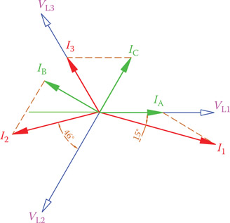
Figure 9.31
Line currents and phase differences with their voltages for Example 9.15.
9.8 Chapter Summary
- All commercial electricity production and industrial usage are in three-phase AC.
- Three-phase electricity is more efficient and needs fewer wires than equivalent single-phase AC.
- Three-phase electricity transmission requires three lines, but a fourth line, called the neutral line, can also be used.
- Three-phase load has three similar elements.
- In a three-phase system the voltages between each pair of wires are not in phase with each other. They are out of phase by 120°.
- Connection of a generator or a load to the three lines can be performed in two different ways: delta connection and wye connection.
- Current in the transmission lines is called line current. The current in the load elements is called phase current.
- The voltage between each pair of wires is called line voltage. The voltage across the load elements is called phase voltage.
- In wye connection the phase current and the line currents are equal.
- In wye connection the voltage across each load element is less than the line voltage.
- In delta connection the voltage across each load element is equal to the line voltage.
- In delta connection the phase current is less than the line current.
- A balanced load has exactly the same load types and values for each of the three load elements.
- All three-phase loads are balanced loads.
- For a balanced load the current in the three wires are the same in magnitude but are out of phase by 120°.
- If a load is connected in delta, it takes more current and more power from a circuit compared with if wye connected.
- A wye-delta switch is used to connect a load first with wye connection before changing to delta connection to reduce the inrush current.
- Vector representation is a convenient way of showing the phase relationships in a three-phase system.
- A vector diagram showing all the voltages and currents in a three-phase system is called a phasor.
Review Questions
- What are the main differences between single-phase and three-phase systems?
- What are the advantages of three-phase systems over single-phase electricity?
- Can a three-phase load be connected to single-phase electricity? Why or why not?
- How many wires are required for transmitting three-phase electricity?
- Why are three-phase systems more common in industry?
- What is meant by phase current and phase voltage?
- How is the load connected to electricity in delta connection?
- What is the difference between delta connection and wye connection?
- What is the difference between wye connection and star connection?
- What is the voltage between each pair of wires in a three-wire system called?
- Can a three-phase system have four wires?
- Is phase current larger or line current?
- Is phase voltage larger or line voltage?
- Can three different single-phase loads be connected to three-phase electricity?
- Does the term apparent power apply to three-phase electricity?
- Is the electricity at home single phase or three phase?
- What is the difference between a three-phase load and a single-phase load?
- How can you make a three-phase capacitive load out of three capacitors?
- Can three single-phase sources be put together to make a three-phase source? Why or why not?
- Does power factor correction apply to three-phase electricity?
- In which of the four cases shown in Figures 9.12 and 9.13 is the current in the wires lowest for the same load elements, if the phase voltage generated by the source is 220 V?
Problems
- A three-phase heater is 10 kW and the power line is 220/380 V. The heater is delta connected. Find the current in the line.
- If after a repair by mistake the heater in Problem 1 is wye connected, what is the power it delivers?
- If 1 W = 0.483 cal/sec, how much is the difference between the calories expected and the calories that the heater provides when it is not correctly connected, in one hour?
- The fuse (three of them) used in the heater of Problem 1 must allow 20 percent more than the current taken by the heater, what is the size of the fuse to be used?
- If one of the fuses in the heater of Problem 1 blows out and disconnects its line, find out how much is the current in the lines and how much is the power delivered by the heater?
- Each element of a three-phase load is a 10 Ω resistor. For each of the four scenarios shown in Figures 9.12 and 9.13, find the current in the wires connecting the load to the generator if the phase voltage in the generator is 220 V.
- Each element of a three-phase load can be assumed to consist of an inductor and a resistor in parallel. The load is delta connected. If the line current is 35 A, the line voltage is 400 V, and the power factor is 0.55, find the resistance of the resistive part of each load element for both wye and delta connection.
- If for Problem 7 a bank of delta-connected capacitors is used to increase the power factor to 100 percent, what is the size of each capacitor if the operating frequency is 50 Hz?
- If a set of delta-connected 100 μF capacitors are used for the load of Problem 7, what is the power factor?
- For Problem 9, draw the phasor diagram before and after exerting the capacitors.
- A 12 kW wye-connected resistive load and a 15 kVA delta-connected load are fed by the same circuit. What is the apparent power of this circuit, and what is the power factor if the power factor of the second load is 70 percent? The line voltage is 480 V.
- Three different loads are connected in delta across a 400 V, 50 Hz three-phase line. Determine and show the current and voltage in the vector form (phasor diagram). The loads are as follows:
- Load 1: 28 kW, with pf = 1
- Load 2: 22 kVA, with pf = 0.75, leading
- Load 3: 18 kVA, with pf = 0.85, lagging
Advanced Learning: Mathematical Representation of Three-Phase Systems
Introduction
Alternating current electricity is generated by electric generators, which are rotary machines. This is why the voltage and current in AC electricity have a sinusoidal form. Therefore, mathematically an AC voltage can be defined by a sine or cosine function. Often, a cosine function is used, but because in this book all figures representing an AC voltage start at zero, we use a sine waveform for this purpose in order to accord.
Voltage is the principal variable in an AC circuit, which results in the current in a load to have also the same waveform, either in phase with the voltage or out of phase with it, depending on the load.
In this section we include the main formulation for the mathematical representation of an AC system, with the emphasis on three-phase electricity.
Expression for AC Voltage
Time variation of a single-phase voltage can be represented by
| (A9.1) |
where V is the amplitude at each instant, Vpeak is the peak value of the voltage, which is a constant, ω is the frequency expressed in radians per second (and not in Hz), and t denotes the time. With the change of t the voltage V traces a sinusoidal waveform. The relationship between ω and f (the frequency in Hz) is
| (A9.2) |
When another waveform, such as current, is in phase with the voltage in Equation A9.1 it can be expressed as
| (A9.3) |
and if it is lagging the voltage by an angle θ, it can be written as
| (A9.4) |
Similarly, if the current leads the voltage by θ, the expression is
| (A9.5) |
Note that since ω is in rad/sec, ωt is in radians and, thus, θ must be defined in radians (and not in degrees).
Three-Phase System
In a three-phase AC system, there are three voltage values that are out of phase with each other by 120°. Denoting the three voltages by VA, VB, and VC, and assuming a zero value for VA at time t = 0, the expressions for the three phase voltages are (note that 120° = 2π/3 rad.):
| (A9.6) |
| (A9.7) |
| (A9.8) |
where Vp denotes the peak voltage and ω is as defined in Equation A9.1.
(Equally, we could use cos function, but then at time t = 0 VA is at its peak.)
The above three voltages are the outputs of a generator in a three-phase system. It can be seen that at each instant of time the sum of all the voltages is equal to zero. This property, in fact, allows us to put the three lines together to make a wye connection; otherwise, we cannot (and should not) join three points with a voltage difference between them. Also, from these equations one can find the expressions for the voltage difference between each two phases, as it is used in delta connection.
For both tasks, showing that the sum of the three voltages is equal to zero and finding the voltage difference between the phases, we need to use the trigonometric relationships for the sum of angles. These relationships are repeated here for convenience.
| (A9.9) |
| (A9.10) |
Hence,
| (A9.11) |
| (A9.12) |
The sum of the three voltages accordingly is
VA + VB + VC = Vp [sin (ωt) + sin (ωt) cos (2π/3) − cos (ωt) sin (2π/3) + sin (ωt) cos (2π/3) + cos (ωt) sin (2π/3)] = Vp [sin (ωt) + 2 sin (ωt) cos (2π/3)]
But cos (2π/3) = −0.5 and 2 cos (2π/3) = −1.
Therefore,
| (A9.13) |
The following lines derive the values for phase-to-phase voltages, denoted by V1, V2, and V3. We are going to use Equations A9.10 to A9.12. Also, the constant values can be substituted for. That is, and cos (2π/3) = −0.5, cos (−2π/3) = −0.5, etc. Some mathematical manipulation is necessary to express the results in a useful form.
The expression in the bracket can be written as
which can be simplified to − cos(ωt + 120°).
As a result,
| (A9.14) |
Thus,
| (A9.15) |
A treatment similar to what was done for V1 leads to
or
| (A9.16) |
The expressions given in Equations A9.14, A9.15, and A9.16 clearly show the important facts for V1, V2, and V3: (1) that their variation with time is sinusoidal, (2) that these values are larger than VA, VB, and VC by a factor of and (3) that they have a phase difference of 120° from each other.
We may want to express V1, V2, and V3 as sine functions rather than cosine. In this way we can directly compare them with VA, VB, and VC. The following lines indicate this modification, in which we use the two basic relationships:
cos x = sin (90° − x)
−sin x = sin (−x)
| (A9.17) |
| (A9.18) |
| (A9.19) |
Figure A9.1 illustrates the vectors associated with VA, VB, and VC, and their relationship with V1, V2, and V3. Figure A9.1 is a modified version of Figure 9.24b in order to accord with using sine function.
When a balanced three-phase load is powered by a voltage source expressed by Equations A9.6 to A9.8 or A9.14 to A9.16, the resulting current has a sinusoidal waveform. Employing the same approach as used for Equation A9.13, it can be proved that the sum of the currents at each instant equals zero.
IA + IB + IC = 0
or
| (A9.20) |
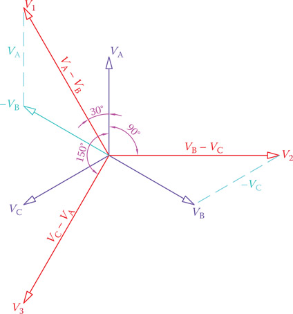
Figure A9.1
Vector representation of phase and line voltages based on mathematical relationships.