
7
DC Motors and Generators
OBJECTIVES: After studying this chapter, you will be able to
- Define a magnetic field
- Differentiate between a magnet and an electromagnet
- Determine poles of an electromagnet
- Express fundamentals of DC electric motors
- Explain Lorentz force
- Understand components of a DC machine and the importance of each one
- Define the characteristic curve for the performance of a machine
- Explain similarity between a DC motor and a DC generator
- Describe Faraday’s law in electricity
- Describe the difference between various types of DC motors
- Understand the use of different DC motors for different applications
- Understand the rules of batteries in series and in parallel
- Explain the conditions to put DC generators in parallel together
- Define rated value(s) for an electric machine
- Describe what efficiency is
- Explain why efficiency can never be 100 percent
- Calculate the efficiency of a motor
New terms: Armature, back electromotive force, brush, characteristic curve, commutator, counter electromotive force (EMF), cumulative compound wound, diamagnetic, differential compound wound, electromagnet, ferromagnetic, long shunt compound, magnetic field, paramagnetic, performance curve, permanent magnet, prime mover, rated value, servomotor, short shunt compound, slip rings
7.1 Introduction
One of the properties of electricity is magnetism. All motors work based on this property of electricity and its effects, as you will see in this chapter and Chapter 11. This chapter covers the fundamentals of DC machines. The reason why the term “machine” is used here is that the basic construction of a motor and a generator, particularly for DC electricity, is the same. A machine can be used as a generator (converting mechanical energy to electrical energy) or a motor (converting electrical energy to mechanical energy).
There are many different types of motors, particularly in AC electricity, but in this book we discuss only the construction of major motors, because the variety in structure and physical differences can give different properties for the operation of a motor. Also, the discussion of magnetism, by itself, is very involved and falls beyond the scope of this book. We just discuss the matter very briefly.
7.2 Magnetism
Certain metals of the iron family can become magnetized if their atoms align such that this property is enhanced. This alignment can be due to contact with another magnet, electricity influence, being placed in a magnetic field (being in the vicinity of a magnet), or by natural events in nature. As a result of magnetism, magnetic media can attract or reject other media by inserting attraction force or rejection forces on them.
In nature the metallic form and salts (compounds) of the ferromagnetic materials can be found as magnets. This is the way magnetism was first recognized. Ferromagnetic materials are those that can relatively easily become magnets, and they can retain their magnetism. Some other materials, called diamagnetic materials, can never become a magnet. A third category is called paramagnetic materials, which can exhibit a very small degree of magnetism, but they can never retain it.
Ferromagnetic: Type of material from the iron family that is suitable for magnetization.
Diamagnetic: Materials without any significant magnetism property, such as wood and clay. They can never become a magnet.
Paramagnetic: Metals with very little (negligible) magnetic property that never can retain any magnetism after being in a magnetic field, as opposed to ferromagnetic materials.
Examples of ferromagnetic material are iron, steel, chromium, and nickel. Examples of diamagnetic material are copper, lead, mercury, silver, tin, and graphite (carbon). Examples of paramagnetic material are tungsten, aluminum, magnesium, sodium, and titanium.
A magnetic field is a part of the space around a magnet that the magnetic influence can be felt and measured. For example, there is a magnetic field between the two poles of a horseshoe magnet, as shown in Figure 7.1. Also, the Earth has a magnetic field, between North Pole and South Pole. To elaborate on the meaning of field, consider the Earth also having a gravity field. As one moves away from the Earth, the gravity field becomes weaker until it becomes so small that it can be ignored. At that point, everything becomes weightless. A field can be assumed to consist of a number of imaginary lines that show the orientation of the field. For example, for a magnetic field we always consider the direction to be from North Pole to South Pole, and the gravity field around the Earth, it is always toward the center of Earth. For a magnetic field these lines are called flux lines.
Magnetic field: Limited part of the space around a magnet where the magnetic effect exists.
Flux lines: Imaginary lines around a magnet indicating the direction of magnetic effect. Stronger magnetism effect implies more flux lines through the same area.

Figure 7.1
Magnetic field.
As well as orientation, a field has strength. This strength is not constant. A magnetic field can be strong, or it can be weak at a certain point. As one moves away from the magnetic field, it becomes weaker. For instance, the magnetic field in Figure 7.1 is stronger at point A than at point B. A stronger field can be assumed to have more lines (magnetic flux lines) per area; that is, the flux lines are denser.

Figure 7.2
Direction of a magnetic field inside and outside the magnet body.
As you know, a magnet can be in various forms, a yoke or a bar, for instance. No matter what the shape of a magnet is, the magnetic field direction is always from North pole toward South pole outside the magnet body along the flux lines and from south to north inside the magnet. The magnetic flux lines form closed curves. This is as shown in Figure 7.2.
As we will see shortly, a magnetic field can be created by electricity. The core body of such a magnet loses its magnetic property when electricity is turned off. However, many magnets do retain their magnetism. These are called permanent magnets. Today, strong permanent magnets can be made from alloys of rare metals and iron. They are employed in many motors and recently in some small generators such as those in some wind turbines.
Permanent magnet: Magnet with permanent magnetic property that cannot be turned on and off or altered.
The magnetic property of a permanent magnet is due to its atomic structure. Thus, if a bar magnet is broken in the middle, each piece by itself becomes a perfect magnet having two poles, one north and one south. In the same way, if each of the two broken magnets is divided again into pieces, each piece becomes a magnet. Inversely, two magnets can be attached together only when their opposite poles are put together. This is why opposite poles attract and similar poles repel each other.
Heat is not good for a permanent magnet. A magnet can lose it magnetism by being heated. This changes the atomic structure of the metal. So, if you want to destroy a magnet, you can heat it. Alternatively, if a magnet is struck hard by a hammer, it will lose its magnetism.
A ferromagnetic material can easily become a magnet.
7.3 Electricity and Magnetism
One of the properties of electricity is magnetism. When electric current passes through a conductor, an electric field is generated around the conductor. This can be checked by placing a compass near the current carrying wire. The compass needle aligns itself with the field generated by the electric current. This is shown in Figure 7.3. Each piece of the wire creates a magnetic field around it. The field lines are circles perpendicular to the wire segment; thus, depending on the point on this circle, the direction of the magnetic field changes. The needle of a compass always stays tangent to the magnetic lines. This magnetic field is all around the wire; so, for a straight wire the magnetic field forms a cylinder.
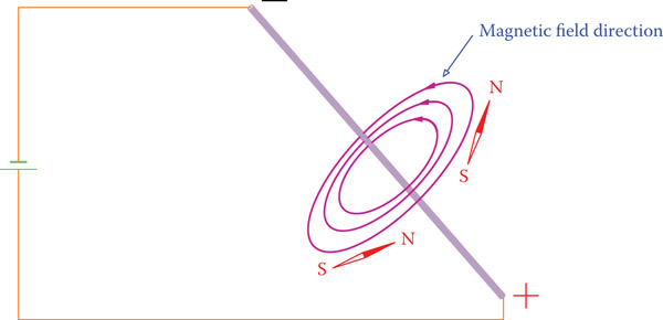
Figure 7.3
Magnetic field of a current carrying wire.
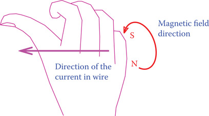
Figure 7.4
Right-hand rule to find the direction of the magnetic field around a wire. (From Hemami, A., Wind Turbine Technology, 1E ©2012 Delmar Learning, a part of Cengage Learning Inc. Reproduced with permission from http://www.cengage.com/permissions.)
Note that in Figure 7.3 the current direction is from positive to negative, using the conventional direction of current. The direction of the magnetic field generated this way can always be found by the right-hand rule, as shown in Figure 7.4. That is, if the thumb in the right hand is aligned with the current direction, the fingers show the magnetic field direction.
The strength of this magnetic field depends on (1) the current in the wire and (2) the distance from the wire. The higher the current is, the stronger the field is. Also, the farther from the wire, the weaker the field is.
7.3.1 Magnetic Field of an Inductor
An inductor is a wound wire: when connected to electricity, it carries a current. In the previous section we learned that if a straight wire carries a current, then a cylindrical magnetic field is created around it. In the case of a coil (an inductor) the wire is circular, and normally there are a large number of loops that carry the same current. In this sense, there are many magnetic fields created because of the electric current, and they interact with each other owing to the loops in the wire. Figure 7.5 shows what happens in such a case.

Figure 7.5
Magnetic field of a coil. (a) Field direction for each individual loop. (b) Resultant magnetic field of all loops.
For each loop in the coil the magnetic fields form a torus around the loop. Magnetic lines at two points are shown in Figure 7.5a. At some points (such as A and A′), magnetic lines are in the opposite direction and cancel each other, but at some other points (such as B and B′) they combine with each other and their effects add together. The resultant magnetic field for each loop is along a line perpendicular to the loop (along the loop axis). Magnetic fields of all the loops, then, add together to construct the magnetic field of the coil. This field is along the coil axis, as shown in Figure 7.5b.
In conclusion, when a coil carries electric current, a magnetic field is generated. The direction of this magnetic field depends on the direction of the current. Figure 7.6 shows a coil and the direction of its magnetic field based on the electric current direction. As noted before, the direction of the magnetic field is from north to south outside of the magnet generated by the current flowing in the coil (from + toward −).

Figure 7.6
Direction of the magnetic field of a coil.
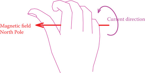
Figure 7.7
Right-hand rule to find the direction of the magnetic field of a coil. (From Hemami, A., Wind Turbine Technology, 1E ©2012 Delmar Learning, a part of Cengage Learning Inc. Reproduced with permission from http://www.cengage.com/permissions.)
Moreover, the field strength depends on the current as well as other factors, such as the physical dimensions of the coil and the material of its core. To enhance the magnetic field of a coil, a core made of a ferromagnetic material is inserted inside the coil.
The right-hand rule again can be helpful here to determine which side is the north and which side is the south, knowing the current direction. This is shown in Figure 7.7. This rule states that if your right-hand fingers are in the direction of current, then your thumb indicates the direction of the magnetic field (the thumb shows the north pole of the resulting magnetic field). Study this figure together with Figure 7.6. Also, note the difference between Figures 7.4 and 7.7.
The right-hand rule states that if your right-hand fingers are in the direction of the current in a coil of wires (from + toward −), then your thumb indicates the north pole of the coil magnetic field.
7.3.2 Electromagnet
The magnet created by the coil in Figure 7.6 is not a permanent magnet. As soon as the current is turned off, the magnetic field vanishes and the magnetic effect disappears. This arrangement (a coil and a core in it) is called an electromagnet, and it has many industrial applications. As you might imagine, it can be used for collection of (ferromagnetic) metals and for exerting force, in addition to many other applications such as opening and turning a switch or a valve on and off.
Electromagnet: A (not permanent) magnet made by a wire coil wrapped around a ferromagnetic core when carrying an electric current. The magnet can be turned on and off or its strength can be adjusted.
7.4 Lorentz Force
Many motors work based on Lorentz force. It is a force that is created because of the interaction of a magnetic field and electric current. If a wire carrying electricity happens to be inside a magnetic field, then a force is exerted on the wire. This force has a direction that depends on both the direction of current and the direction of the field (see Figure 7.8). Also, as can be expected, the magnitude of this force depends on the current and the strength of the magnetic field.
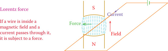
Figure 7.8
Definition of the Lorentz force.
The direction of the Lorentz force can be determined from the right-hand rule, as shown in Figure 7.9. The right-hand rule for the Lorentz force states that if the right-hand fingers are along the magnetic field and the thumb is in the direction of the current, then the direction of the force exerted on the wire is along an arrow coming out of the palm.
Lorentz force law: If a wire is inside a magnetic field and carries electricity, then a force is exerted on the wire.
Armature: Rotating part in a DC machine, especially the windings of this rotating part.
Brush: Solid block component made mainly from carbon (can have other substances such as metal powder) for transferring electricity from a rotating part to the stationary part in a motor and generator. The brush is stationary and pressed by springs on the rotating rings/segments.
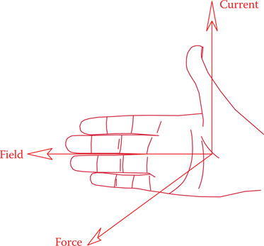
Figure 7.9
Right-hand rule for determination of the Lorentz force direction. (From Hemami, A., Wind Turbine Technology, 1E ©2012 Delmar Learning, a part of Cengage Learning Inc. Reproduced with permission from http://www.cengage.com/permissions.)
A DC motor consists of a winding (many loops of wire), called an armature, that when connected to electricity an electric current will pass through all its loops. A motor also has a magnet that provides the necessary magnetic field. The armature is inside the magnetic field and can rotate about its axis. A force is exerted on each of the individual wires in the armature. All this force leads to a motion, and with proper arrangements the armature has a rotational motion about its axis. This is shown in Figure 7.10 for one loop. To provide electricity for a rotating component, use is made of a brush and slip rings, schematically illustrated in Figure 7.10. A brush having a fixed position can slide on a cylindrical surface that rotates.
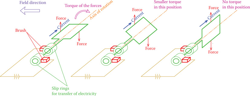
Figure 7.10
Principal structure of a DC motor.
In practice, an armature always has a metallic core. It is not a hollow frame of wires. An armature core is very important for the operation of any electric machine, because without it a large percentage of available power is lost. The armature core holds the windings; it is made up of laminated iron or steel (a ferromagnetic material) and is part of the structure of the entire rotating part of a machine. Figure 7.11 illustrates a typical armature assembly consisting of the armature windings, armature core, and a commutator, all mounted on a shaft.
Commutator: Part of the armature of a direct current motor or generator consisting of many small metallic (normally copper or brass) segments in the form of a ring which can slide under a brush. The brushes are spring pressed on the commutator and transfer the current from the rotating commutator to the outside of the armature. The commutator has the role of rectifying the otherwise AC current in the armature.
Slip rings: Set of two (in single-phase) and three (in three-phase) in some types of AC electric machines that are connected to windings that rotate with the rotor. Brushes pressed by springs on the slip rings can transfer electricity from or to the winding from the external circuit.
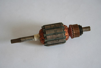
Figure 7.11
Example of an armature assembly.
As can be understood from the Lorentz force law, and as illustrated in Figure 7.10, for each loop of the armature, there are two forces exerted to the two sides of the loop. The relative directions of these forces vary with the loop angle with respect to the magnetic field, and, consequently, their resulting torque about the axis of rotation changes between zero and a maximum value. Moreover, after 180° of rotation, the directions of the two forces (and consequently the direction of their torque) change, which is not suitable for a continuous rotating motion. This is shown in Figure 7.12. To keep the torque in the same direction so that the armature shaft continues moving in the same direction, it is necessary to alter the direction of the current in the armature at a certain position. This alteration of current in a DC motor is achieved by a commutator. Instead of the two slip rings for transfer of electricity (in Figure 7.10), if two half rings are used (isolated from each other), as they rotate with the shaft, the brushes change contact from one to the other. In this way the connections to a power supply, and subsequently the current direction, switch. Each DC motor (and generator) has a commutator, which is a mechanical device to change the direction of current in its armature and maintain the torque direction. In practice, there is more than one loop, and, therefore, instead of two half cylinders, there are many smaller cylinder segments put together, each one isolated from the rest, and all isolated from the shaft body. The two ends of each loop of the armature are connected to two of these segments 180° apart. Each loop by itself can comprise a bundle of looped wires (in series with each other), the two ends of which are connected to the segments on the commutator.
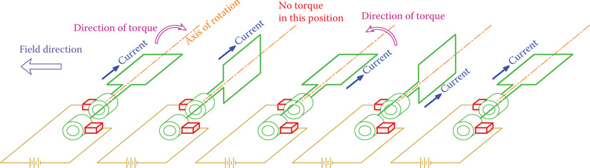
Figure 7.12
Change in direction of force (and torque) after 180° of rotation.

Figure 7.13
Commu tator in a DC motor.
A commutator is illustrated in Figure 7.13. It consists of a number of copper segments that are arranged around the periphery of a cylinder. Each opposite pair of these segments is connected to the two ends of one of the loops of the armature, and, therefore, a commutator has twice as many segments as the number of bundle loops in the armature. The concept of a commutator can be more clearly understood from Figure 7.14, which shows only two loops and four commutation segments. Copper segments in a commutator are connected to the power supply through brushes that can slide on the commutator when it rotates. Thus, the brushes are stationary and do not rotate. Brushes are made of carbon (or a similar manufactured electric conductive material, containing carbon) and are spring loaded (sufficiently pressed on the commutator by some springs) to have a good contact. Otherwise, they spark in operation. Normally, a brush can cover a few of the commutator segments. Therefore, more than one loop is connected to electricity at a time. These are the loops with maximum force and giving maximum torque to a motor shaft (see Figure 7.15). After a few degrees of rotation each loop disengages and another loop substitutes for it. Thus, during one revolution a motor always benefits from engaging the part of winding that gives the highest torque, while the rest of the loops carry no current.
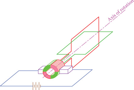
Figure 7.14
Four commutator segments for two-loop armature. (From Hemami, A., Wind Turbine Technology, 1E ©2012 Delmar Learning, a part of Cengage Learning Inc. Reproduced with permission from http://www.cengage.com/permissions.)
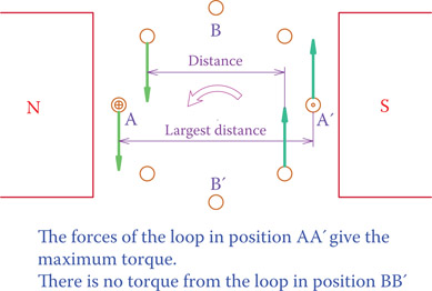
Figure 7.15
Loops with maximum and minimum torque.
A commutator is a mechanical device that by switching connection points while turning changes the direction of current in the armature of a DC machine.
7.5 Faraday’s Law
Faraday’s law is the opposite of Lorentz force law. It states that if a wire is moved inside a magnetic field such that it cuts the magnetic flux lines, then an electromagnetic force is generated in that wire (a voltage difference is created between the two ends of the wire). This is the principle of operation of a generator. Figure 7.16 shows this law for one single wire. As shown, the direction of motion is perpendicular to the direction of the magnetic field flux lines; it, therefore, cuts the flux lines.
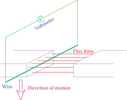
Figure 7.16
Faraday’s law, the principle of working of a generator.
If a wire moves inside a magnetic field such that it cuts the magnetic flux lines, an electromotive force is generated in that wire.
Figure 7.17 illustrates the same wire and the same magnetic field as in Figure 7.16, except that the motion of the wire is in parallel with the direction of the flux lines, and therefore the lines are not cut by the wire. In such a case, no voltage difference is generated in the wire. In general, when a wire moves inside a magnetic field, its motion can vary between these two cases, thus, partly perpendicular and partly parallel to the magnetic field lines. The generated voltage is always proportional to the component of motion that is perpendicular to the field lines (any motion can be decomposed into two components in two perpendicular directions).

Figure 7.17
No voltage is generated in the wire because it moves parallel to flux lines.
In a generator, there are a large number of wires, and they are in the form of loops that during rotation of the generator shaft move through a magnetic field and cut the magnetic field lines. Figure 7.18 depicts one of these loops. Voltage generation takes place only in the parts of each loop of wire that are parallel to the axis of rotation. The other segments are to complete the loop and connect it to the outside. Moreover, when rotating, the two sides of a loop move in different directions. For example, for a counterclockwise rotation of the loop in Figure 7.18, when the segment AB of the loop moves downward, the segment CD moves upward. As a result, the voltages generated in the two opposite sides of a loop of wire are in the opposite directions and therefore add together (if they were in the same direction, they would oppose and cancel each other). The direction of the electromotive force generated in a wire in relation to the direction of the magnetic field and motion direction is determined from the right-hand rule. This rule is different from that for the Lorentz force, and it is shown in Figure 7.19. Compare this figure with Figure 7.9 to notice the difference.
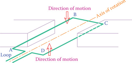
Figure 7.18
Counterclockwise rotation of one loop of the winding in a generator.
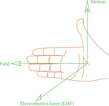
Figure 7.19
Right-hand rule for a generator. (From Hemami, A., Wind Turbine Technology, 1E ©2012 Delmar Learning, a part of Cengage Learning Inc. Reproduced with permission from http://www.cengage.com/permissions.)
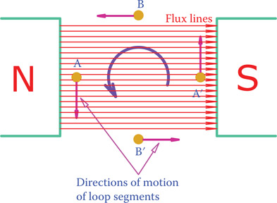
Figure 7.20
Maximum voltage corresponds to position AA′ and zero voltage at BB′.
Voltage generated in a loop depends on the position of the loop with respect to the magnetic field. This electromotive force is not the same in all positions within a 360° range. The cross section of one loop is shown in Figure 7.20. The direction of motion is shown for the wire segments in the loop. When the loop assumes the position shown by points B and B′, direction of motion of the wires in the loop is parallel to the flux lines. Consequently, no flux lines are cut, and no voltage is generated. As the rotation takes place and the angle of the loop changes, more and more flux lines are cut by the wires, and in the position defined by points A and A′ the number of wires cut by the wire is the maximum. Thus, generated voltage is at a maximum in this position.
7.6 DC Machines
In electricity the word machine is used for both a motor and a generator. When an electric machine is turned by a prime mover, it converts mechanical energy to electrical energy, thus behaving as a generator. When electricity is applied to the machine, it converts electrical energy to mechanical energy, thus functioning as a motor. Therefore, a DC machine is an electrical machine that works with DC electricity as a motor or produces DC electricity as a generator. A basic DC machine can behave as a motor or a generator. (Today’s machines are sometimes composed of a basic machine and additional circuitry for specialized functions, like embedded electronic circuits. Thus, they may not readily function two ways.) Construction and electrical components of a DC motor and a DC generator are, therefore, the same, and it is not necessary to repeat the common features, particularly those associated with their structure.
Prime mover: Mechanical power source (e.g., steam turbine, gas turbine, diesel engine) that turns an electric generator or any other device requiring mechanical energy.
As it was mentioned in Section 7.4 for a DC motor, in order for a DC machine to work, a magnetic field is necessary, inside which the armature rotates. The armature is mounted on a shaft, which is attached to the stationary body by bearings at its ends. Connection of the armature (rotating part) to the outside (stationary) is through the commutator. Here we consider a number of scenarios according to which a DC machine can be constructed. The difference between these scenarios lies in the way the magnetic field is created. Because the performance of a DC machine depends on the interaction between the magnetic field and the current in the armature, the difference between these various scenarios affects the performance of the machine. Performance is normally the relationship between the torque (load) and speed or between the speed and the applied voltage (for generator the speed and the generated voltage). This relationship is depicted by a curve referred to as the performance curve or the characteristic curve.
Performance curve: Same as characteristic curve: A line or curve that shows the relationship between two or more parameters related to the performance of a device.
Characteristic curve: Line or curve that shows the relationship between two or more parameters affecting the functionality of a device, like the relationship between voltage and speed in an electric motor.
Permanent magnet: The (magnetic) field in such a machine is provided by a permanent magnet. The magnetic strength of this field is constant in all conditions. Figure 7.21 shows the schematic of a permanent magnet (PM) DC machine. The geometrical arrangement of the magnetic field and the armature can vary. Normally, magnetic poles in a DC machine are salient, as opposed to some other machines that the poles are not physically distinguishable. Operation of a permanent magnet machine is smooth, and compared with other classes, its power loss is smaller owing to not having any magnetizing coil. Nevertheless, there is a limitation to the power capacity of such a machine.

Figure 7.21
Schematic structure and pole arrangement of a permanent magnet DC machine.

Figure 7.22
Separately excited machine.
Separately excited machine: In this configuration, shown in Figure 7.22, the magnetic field is provided through an electric current passing through the field winding. The magnetic field, in fact, is provided by an electromagnet. Two different DC voltages are applied to the machine, one for generation of the magnetic field and one for the armature. Because there are two voltages, the currents in the field winding and the armature are independent and can be separately controlled. This gives the highest degree of control of the machine. A motor made this way is called a servomotor.
Servomotor: Motor whose speed or displacement can be controlled (must be capable of being controlled).
To show the principle of construction of an electric machine more easily, normally, the body is not shown and only the windings and the terminals are depicted. Thus, instead of Figure 7.22, the simpler Figure 7.23 is used. Accordingly, for the rest of the figures the simpler representation is employed.
Series wound DC machine: In this configuration the field winding and the armature winding are put in series with each other, as depicted in Figure 7.24. A single voltage is applied to the open ends of the two windings (terminal voltage), and this voltage is divided between the field winding and the armature winding. In this way, the current in the field winding is the same as the current in the armature. The only thing that can be changed to control and vary the behavior of the machine is the applied voltage.
Shunt wound DC machine: In this case the two windings are in parallel with each other, and, thus, the same voltage is applied to both the field winding and the armature, but they have different currents. Figure 7.25 shows the winding arrangement of a shunt wound DC machine.
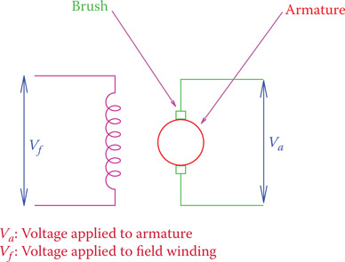
Figure 7.23
Simple schematic of a separately excited DC machine.

Figure 7.24
Series wound DC machine.
Compound-wound DC machine: It is possible to combine the construction of a series wound and a shunt wound DC machine for performance improvement. Such a machine has two field windings, one in parallel with the armature winding and the other one is in series with it. There are various possible ways to have this arrangement, as shown in Figure 7.26. The two arrangements shown are called long shunt compound and short shunt compound machines, respectively.
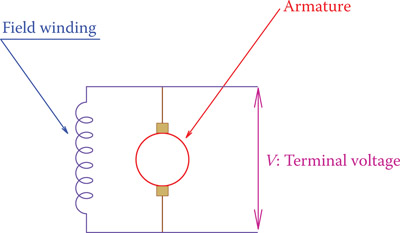
Figure 7.25
Shunt wound DC machine.
Long shunt compound: A kind of compound wound DC electric machine in which the shunt winding receives the entire terminal voltage, as opposed to the short shunt compound machine. The shunt winding current is independent of the series winding current.
Short shunt compound: A kind of compound wound DC electric machine in which the field shunt winding receives only a part of the terminal voltage (The field has a shunt winding plus a series winding). The shunt winding is parallel with the armature winding, only, and the current in the shunt winding is a fraction of the field series winding current.
Note that whereas in the preceding sections a magnetic field was represented by one pair of (north and south) poles, in practice, it is possible to have more poles for the magnetic field. This affects the speed of rotation of a machine. Figure 7.27 depicts when two pairs of magnetic poles are used in a machine.

Figure 7.26
Long shunt compound and short shunt compound DC machine.
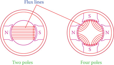
Figure 7.27
Comparison of magnetic field flux lines in two and four magnetic poles.
7.6.1 DC Machines Characteristic Curves
As far as the performance of a machine and its characteristic curves are concerned, for motors we normally are interested in the speed versus applied voltage relationship and torque versus speed relationship. The first category shows the variation of the speed of a motor with the increase in the applied voltage. This is important in applications where the speed of rotation of a load connected to the motor is to be controlled. A hypothetical case (because each case depends on the aforementioned types of a machine) is shown in Figure 7.28. This curve implies that as the voltage is increased, the speed of the motor is also increased, and this increment in speed is proportional to the voltage increase. In other words, the relationship is linear (the curve is, indeed, a line in this case). However, this relationship is true for values above an initial minimum voltage below which a motor does not move owing to friction.
The second category exhibits the relationship between speed and torque. This curve is very important when matching a load to a motor (or vice versa). When running a load by a motor, the power requirement of the load must be satisfied by the motor. That is, if at any instant the motor cannot provide the power demanded by the load, it can slow down, or even stall. Because power in a rotating system depends on the product of the rotational speed and the torque on the shaft, the operating point is always a point when the torque-speed curve of the load and the torque-speed curve of the drive meet, as shown in Figure 7.29 for a typical case (the load curve corresponds to a fan or blower). Point A in this figure is the operating point for a particular situation. If the speed of the load is to be increased, say to that of point B, the demand for torque also increases (based on the load characteristic curve). In such a case, either the applied voltage to the motor must be increased (so that a new curve passing through point B defines the motor characteristics), or the motor cannot run the load at the new speed (if either the maximum allowed voltage or the motor maximum power is reached). A motor and its load always come to a balance (equilibrium) with each other. This equilibrium point defines the operating point.

Figure 7.28
A characteristic curve indicating a linear relationship between applied voltage and motor speed (load torque is constant).

Figure 7.29
A typical torque-speed curve for a motor and for its load.
In Figure 7.29 the curve for the load signifies that the required torque increases as the speed increases. This is a typical situation for many devices such as pumps, fans, compressors, and blowers.
Power demand in a rotating load equals the product of the rotational speed and the torque on the shaft.
A motor and its load always run at an equilibrium speed, which is the point of intersection of their torque-speed characteristic curves.
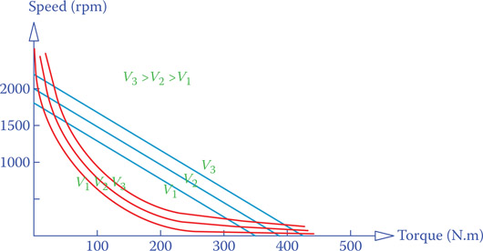
Figure 7.30
Two sets of speed-torque characteristic curves for two different types of DC machines.
The speed-torque characteristic curve can be drawn differently, showing speed on the vertical axis and torque on the horizontal axis. This does not change the property of a machine under study. Either curve can serve the purpose of studying the variation of one parameter in terms of the changes in the other. Usually, the variable that is susceptible to variation is shown on the horizontal axis. In many loads the torque is the variable subject to change. For example, in a lift depending on the number of people, and in lifting loads depending on the weight of the load, torque on the shaft changes. Figure 7.30 shows two sets of graphs showing the speed-torque relationships but with the two axes interchanged compared to those in Figure 7.29. Three separate performance curves between (angular) speed and torque are shown for each set. Each one corresponds to a different applied voltage. It is a common practice that a set of curves are shown on the same graph, which, in fact, brings the effect of changing the applied voltage into view.
Another class of characteristic curve that can be useful is the relationship between the torque and the current that a motor takes to run (usually the current in the armature). We show that later for particular motors.
For a generator, normally, the voltage that it delivers is of more concern. Thus, the two types of curves of interest are voltage-speed graph, indicating the output voltage variation with the speed at which the generator is turned and the voltage-current curve that determines the output voltage at various loads (electric loads connected to a generator). Two typical curves are depicted in Figures 7.31 and 7.32, respectively. In both cases the third parameter is assumed to be constant; otherwise, one cannot represent the corresponding variations on two axes. This is why often a series of curves are shown for different values of the third parameter (like in Figure 7.30).

Figure 7.31
Voltage versus speed of rotation in a DC generator (load kept constant).
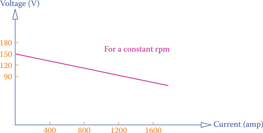
Figure 7.32
Voltage versus current (load) in a DC generator (speed kept constant).
It is to be noted that the characteristic curve in Figure 7.31 does not imply that for all the values of speed there is a corresponding value for voltage. For instance, if one runs the generator at 25 rpm, then a very low voltage can be generated. Any machine must be operated in the range of values for which it is designed. A generator, for instance, may have been designed to run at around 1500 rpm. This speed is the rated value for the machine. The rated value does not need to be a single figure; for example, a machine can have a rated speed between 1000 and 1750 rpm. The fact that the curve in Figure 7.31 passes through the origin implies that theoretically if the rpm is zero then zero voltage is generated.
Rated value: Value(s) affecting the operation of a device that the device is designed for and must operate under conditions within the neighborhood of those values. For example, an electric device has a rated voltage and current. Operating the device outside of the rated conditions is either inefficient or harmful to the device.
Performance of DC machines is based on two general equations. The first equation determines the torque developed in a DC machine. This torque is proportional to the strength of the magnetic field and to the armature current. Thus,
| (7.1) |
where T is the torque, ϕ is the field strength, Ia is the armature current, and K is a constant that depends on the physical size and design of a machine as well as the units that are used for T, ϕ, and Ia.
The second equation is based on the fact for all electrical motors that if a motor is prevented from turning a very high current passes through its winding and as the speed increases, this current decreases. This is why a motor can be damaged if is it not turning, either because of overloading (a large load that is beyond the capacity of the motor) or some braking action. In particular, for a DC motor, if the motor is stopped, a high voltage is applied to its armature winding (thus, a high current through it), but as the motor speeds up, a counter electromotive force (CEMF) is developed in the armature that opposes the applied voltage (thus, reduces the effect of the applied voltage). This counter electromotive force (or back electromotive force [BEMF]) depends on the speed of rotation and is directly proportional to it.
Counter electromotive force (CEMF): Same as back electromotive force (BEMF).
Back electromotive force: (BEMF) Electromotive force that is generated in an electric motor due to its rotation (as happens in a generator) and is in the opposite direction to the applied voltage and tends to stop the motor from rotation. It acts as a brake to the operation of a motor.
The second equation can be written in the form of
| (7.2) |
where V is the voltage applied to the armature winding by the line (which depends also on the machine type), Va is the voltage difference causing a current in the armature, VCEMF is the amount of counter electromotive force, N is the speed of rotation, and KN is a constant value that depends on the physical size and design of a machine as well as the units used for the voltage and speed. The value ϕ is the field strength, as in Equation 7.1. It depends on the type of a DC machine and can be constant or variable. Equation 7.2 clearly shows that if the rotational speed is zero (the first moments when a machine starts), the entire voltage V will be applied to the armature, whereas after a motor starts the voltage leading to the armature current is
| (7.3) |
which depends on the rotational speed (note that Equation 7.3 is the same as Equation 7.2). VCEMF is the generated electromotive force in a winding.
Equation 7.3 is employed when a machine works as a motor. For a generator the term counter electromotive force is normally not used, because it represents the generated voltage and it is larger than the terminal voltage V. Thus, for a generator, Equation 7.2 assumes the form
| (7.4) |
where E = KNϕN is the generated voltage, Va represents the voltage drop in the armature winding, and V is the terminal voltage at the generator output.
7.6.2 DC Motors
The general structure of DC motors and the principle of their operation were explained in the previous two sections. In this section we concentrate on the characteristic curves and performance differences between various types of DC motors.
7.6.2.1 Permanent Magnet DC Motor
This motor has a permanent magnet, and the magnetic field strength ϕ is constant (or it is better to say, its variation is negligible). In this case, the only variable in Equation 7.1 is the current Ia. This implies that the variation of motor torque is proportional to Ia or vice versa; that is, the variation of Ia is proportional to the required torque. The latter makes more sense, because as the motor load increases (i.e., increase of torque requirement by a load that must be driven), current in the motor increases. Theoretically, when there is no load, then the current is zero. However, in practice, because of the losses (friction and dissipated heat), even for zero load (zero torque) there is a small current. The theoretical and actual cases are represented by the lines shown in Figure 7.33. Note that this diagram illustrates the variation of a motor torque versus the motor current; it is an additional curve compared to those described in Figures 7.28 and 7.29. Note also that the armature current is, in fact, proportional to the voltage applied to the armature. Consequently, in a version of this diagram instead of current armature voltage could be used.

Figure 7.33
Armature current-torque relationship in a permanent magnet DC motor.

Figure 7.34
Speed-torque relationship in a permanent magnet DC motor.
Figure 7.34 illustrates the speed-torque relationship for a typical permanent magnet DC motor. This relationship is also linear, and the corresponding curve is a straight line. Note that there are a series of lines indicated in Figure 7.34, each corresponding to a different applied voltage (e.g., V1 to V5), where V1 < V2 < V3< V4 < V5. The torque-speed relationship directly follows from Equations 7.1 and 7.3, taking into account Ohm’s law in the armature winding (Va = IaRa) and noting that the magnetic field is constant.
For each characteristic curve (such as the middle one associated with V3), point A corresponds to zero rotational speed. For the applied voltage, this is the highest torque that a motor can deliver. Moreover, point B corresponds to no load rotational speed. This is the highest speed that the motor can turn when voltage V3 is applied to it, but no load can be connected to the shaft. This part of the curves is shown by a dashed line, because it corresponds to a situation that is not normally realistic, or it is outside the range of operation of a motor.
For a constant load (constant torque), the relationship between the applied voltage and speed of a permanent magnet DC motor is as shown in Figure 7.28, and it is not repeated here.
7.6.2.2 Series Wound DC Motor
In a series wound motor, current in the field winding and the current in the armature are the same. Because the magnetic field strength is directly proportional to the current, Equation 7.1, as a result, can be written as
| (7.5) |
where Ka is constant (the product of K and another constant value). The characteristic curve denoting the relationship between the motor torque and the armature current is not linear. For example, for a double value for torque the current increases by 41 percent (based on Equation 7.5: 1.412 = 2).
From the construction viewpoint, in a series motor, wires for the field winding are thicker than their counterparts in the other wound-field DC motors. This is because the same current flows through both the armature and the field windings. In a motor, wire thickness and the number of loops in various windings are among the parameters that determine the constants such as Ka in Equation 7.4.
One of the distinguishing features of a series wound motor is its very high starting torque. For this reason, series motors are used for loads that need a high torque to start, such as locomotion and lifting equipment, like in trains and cranes. A typical curve is illustrated in Figure 7.35, representing the speed-torque relationship. When such a motor is powered, load must already be connected to it. Otherwise, the motor having a low torque load may develop incremental speed, leading to runaway speed, which is quite dangerous and can cause severe damage of the motor (see the speed corresponding to the no load end of the graph in Figure 7.35).
As discussed earlier, the operating point (which lies within the range of the rated values of a motor) is the point of balance between a motor and its load, found by the intersection of the performance curve for the applied voltage to a motor and its load characteristic curve. For a constant torque (i.e., a load whose torque has negligible variation) any necessary alteration of the motor speed must be done through changing the applied voltage. Figure 7.36 shows a sample of the approximate relationship between voltage and speed.
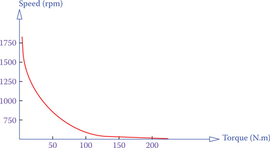
Figure 7.35
Speed-torque relationship in a series wound DC motor.
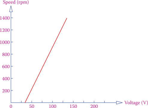
Figure 7.36
Speed-voltage relationship for a constant torque.

Figure 7.37
Speed-torque curve for a typical shunt wound DC motor.
7.6.2.3 Shunt Wound DC Motor
Not all loads require the characteristics of a series wound motor. If the speed of operation of a device must be almost constant irrespective of the load, then a better choice is a shunt wound motor. The speed-torque characteristic curve of a shunt wound motor is a straight line, within the operational region, with a slope better than that of a permanent magnet motor (see Figure 7.34). This is shown in Figure 7.37.
7.6.2.4 Compound Wound DC Motor

Figure 7.38
(a) Cumulative and (b) differential compound wound long shunt DC motor.
Compound wound motors have been invented to improve the performance of the machine in terms of torque-speed and torque-current relationships. Performance of a motor depends on many design parameters; the field arrangement is only one of them. Two methods for combining the series and parallel field windings have been presented in Figure 7.26 (long and short shunt compound). For each arrangement, nevertheless, there are two ways that the field windings can be inserted (connected) inside the machine. Consequently, the two magnetic fields generated by the two windings can be helping each other (added effect), or they can be opposing each other. For the long shunt compound arrangement these two ways are shown in Figure 7.38. As illustrated, in Figure 7.38a the two fields are adding together (see the polarity of the winding denoted by a plus sign), whereas the windings in Figure 7.38b have the reverse polarity. The resulting magnetic field, thus, is equal to the difference between the two magnetic fields. For this reason the first category is called cumulative compound wound motor, and the second category is called differential compound wound motor.
Cumulative compound wound: Type of DC electric machine with both parallel and series field winding where the magnetic effects of the parallel and series windings add together, as opposed to the differential compound wound.
Differential compound wound: Type of DC electric machine with both parallel and series field winding where the magnetic effects of the parallel and series windings are opposite to each other (the magnetic field from the parallel winding is reduced by the smaller magnetic field of the serial winding).
In general, no matter which arrangement is used for a compound wound DC motor, the performance falls between that of a series wound motor and a shunt wound motor. A typical scenario for the speed-torque relationship is shown in Figure 7.39.
To compare the performances of the preceding five types of DC motors side by side, Figure 7.40 depicts the speed-torque performance of them for a common operating point. In application, any motor operates around an operating point within the operating region (rated values) that it is designed for (from the maximum efficiency and power points of view). For any variation of torque around the operating point the variation of speed can be smaller or larger depending on the type of motor. As can be understood from Figure 7.40, a separately excited motor has a much better capability of running at a constant speed, whereas for higher starting torques a series wound motor is preferable (as mentioned before).
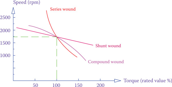
Figure 7.39
Speed-torque curve for a compound wound motor with respect to a series wound and a shunt wound motor.

Figure 7.40
Comparison of the speed-torque curve for all types of DC motors.
7.6.3 DC Generators
In the same way that there are different types of DC motors, one can say, in general, that each one can perform as a generator if rotated by a driver. Nevertheless, the reason for having various types of motor is to obtain a desirable performance of the motor. Except for the separately excited machine and permanent magnet machine, the (magnetic) field must be developed within the machine based on some current flowing through the field winding, which depends on the applied voltage. In this sense, the operation of a machine as a generator must build up from the small amount of magnetism in the core of its armature. This regenerative build up action must continue until a generator reaches its nominal voltage. For certain arrangement of field and armature windings (such as in differential compound winding), where the two fields oppose each other, this build up process may never take place and the machine may never reach the operational condition.
The voltage developed in the armature winding is according to Equation 7.4. Thus, the performance of a DC generator varies with its design. In general, the faster a generator is turned, the higher its voltage.
As stated before, for a generator, one should see the variation of the produced voltage with the load current. This is shown for various types of generators in Figure 7.41, which shows the change in voltage versus the load current around an operating point; it is exaggerated for better clarity. As can be observed from Figure 7.41, except for a series wound generator, the generated voltage decreases with an increase in the line (load) current. This implies that in a series wound generator, if by any reason the current goes up, it further increases the voltage, which, in turn, increases the current. Such an unstable behavior is undesirable and may lead to destruction of a generator. For this reason, series wound generators are not very common. All the other generators have a self-regulatory behavior, and any increase in the load current reduces the voltage (and thus the current), and the machine reaches a stable new working condition.
A series wound DC machine should never be used as a generator.

Figure 7.41
Variation of voltage with the load current in DC generators.
7.7 DC Sources in Parallel
Putting electricity sources in parallel with each other is to provide the required electric power from more than one source. This is out of necessity when expansions occur, and more loads are to be powered by electricity. Remember that the power capacity of power supplies must always be greater than the power demand by the loads.
In DC electricity the condition to be met for electric sources to be put in parallel is that their voltages be equal. In no way can one put a 12 V battery together with a 24 V battery and expect that they both provide electricity to some loads. When the voltages of the sources are the same, the current demanded by the loads will be shared among all the sources. In putting sources in parallel, in fact, the current is distributed among them. If two sources are exactly identical, then their currents are equal.
For connecting sources in parallel the positive sides of all must be connected together and the negative sides together. Then the common positive point is the + terminal and the common negative point is the – terminal. Mistakes in connecting sources together in the right manner lead to damage to the equipment and injury to people.
For putting DC sources in parallel the important necessary condition is that their voltages be equal.
7.7.1 Batteries in Parallel
Figure 7.42 shows three batteries in parallel with each other. A simple example of putting two batteries in parallel is in boosting a weak battery by jumper wires for starting a car on cold winter days. Note that the positive sides must be connected together and the negative sides together. If this is not respected, the weaker battery becomes a load to the good battery and high current flows through the two batteries. This can cause sparks, temperature rise, and even explosion of the batteries.
In connecting batteries in parallel, for the purpose of more power, it is always better to have similar batteries of the same condition, so that the current is equally distributed among them.
7.7.2 DC Generators in Parallel
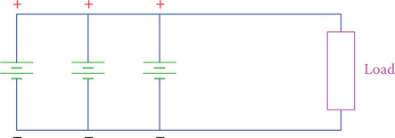
Figure 7.42
Batteries in parallel.
Generators are not exactly like batteries, though both are the sources of DC electricity. Batteries are for low power, while generators can provide large amounts of electric power. Generators can be of different power capacity and different type, while the difference between batteries is not so wide. Combining generators of various types may not always be possible, but different sizes of generators of the same type can be combined. When generators of different sizes are in parallel, the larger generator takes a higher portion of the load current and the smaller generator provides smaller power. For two batteries when the similar terminals are connected together, there is no reason for polarity change. In the case of DC generators, if the voltage of one of the generators decreases (especially if it is smaller and has a lower current), it is possible that eventually it changes state and becomes a motor getting power from the larger generator. Thus, voltage regulation becomes very important in order to prevent this from happening. Voltage regulation for each machine is performed through speed control.
7.8 Efficiency
For a motor to work (produce mechanical energy) it needs to use electrical energy. Also, for a generator to produce electrical energy, it must be fed with mechanical energy. In general, any machine needs energy to work. If the energy that is produced by a machine is called the output energy and the energy that is given to it is called the input energy, the output energy is always smaller than the input energy. The ratio of the output to input energy defines the efficiency of a machine.
To determine the efficiency, it is more reasonable to consider the energy for one second, which is the power. If the output power is denoted by Pout and the input power is represented by Pin, efficiency is represented by the ratio
| (7.6) |
The difference between the output power and the input power is the power that is lost in a machine in the form of heat in the electrical parts (wire windings) and mechanical parts (moving parts). This heat is not recoverable; thus, it is considered a loss of energy.
| (7.7) |
Efficiency is always stated as a percentage. This is the reason for multiplying by 100 in Equation 7.6. Because Pout is always less than Pin, efficiency is always a number less than 100. There is no machine or device with an efficiency of 100 percent. However, it is possible to find machines and devices with a high efficiency, for example, up to 98 percent. But, efficiency can be much lower; for example, in machines with an efficiency of 35 percent (e.g., a combustion engine). Efficiency of motors and generators can reach high values of around 90 percent for well-designed large machines, and it can be as low as 60 percent for small poorly designed machines.
For any machine—electrical, mechanical, or thermal—efficiency is not always constant; it depends on the operating conditions and the output. For some value of the output power the efficiency of a machine is maximum, and for other values it is less than that. Usually, within the rated value of any device its efficiency is near maximum. For example, if a motor is rated for 240 hp, its efficiency is highest at around this power output, but if it is operated at say 120 hp, then its efficiency can be much lower.
Usually, within the rated value of a machine or device its efficiency is the highest.
If a machine or device is made up of several components with known efficiencies, then the entire efficiency of the device depends on the individual efficiencies of its components. In such a case we can calculate the total efficiency as
| (7.8) |
where eff1, eff2, etc. are the efficiencies of the components.
Example 7.1
An electric motor is used for driving a lift. If on one occasion (because the power demand depends on the number of people in the lift) the power consumption is 7.2 kW and the power output (as required by the lift) on the motor is 5 kW, what is the motor efficiency?
Example 7.2
Suppose that the motor in Example 7.1 drives a gearbox whose efficiency is 90% and there is also a pulley system with 88% efficiency. What is the total efficiency of the whole system?
Example 7.3
Suppose that when the lift in the previous examples is at full load, its total efficiency is 75%. What is the efficiency of the motor in this case if the efficiencies of the gearbox and the cable system are assumed to be the same as before?
Solution
For this case we have (Meff is motor efficiency)
which leads to
Example 7.4
If the output power by the motor in Example 7.3 is 8.2 kW, what is the power that the motor takes from electricity?
Solution
Input power (which must be larger than the output power) is a value that if multiplied by the motor efficiency the resultant is 8.2 kW. Thus,
7.9 Chapter Summary
- A magnetic field is the space around a magnet where a magnetic effect exists.
- Only ferromagnetic materials are good for magnetism and magnetic applications.
- An electromagnet is a magnet made up of a coil wound around a ferromagnetic core; its magnetism can be turned on and off.
- Poles of an electromagnet can be determined from the right-hand rule: If the fingers show the direction of current in the winding (from + toward −), then the thumb shows the north pole.
- A DC electric motor works based on Lorentz force, as a result of the interaction between a magnetic field and electric current.
- Lorentz force law states that if a current carrying wire is placed in a magnetic field, then a force is exerted on the wire. Direction and magnitude of this force depends on the magnetic field and the current.
- The right-hand rule for motors states that if the fingers of the right hand are aligned in the direction of the magnetic field and the thumb shows the direction of current, then the direction of the Lorentz force is perpendicular to those two and coming out of the palm.
- Main components of a DC machine are a magnetic field, an armature winding, and a commutator. Armature windings have a ferromagnetic core, and together with the commutator are mounted on a shaft.
- Performance of any machine can be observed from its characteristic curve, which shows the variation of a parameter like the developed torque in a motor versus another parameter such as the voltage applied to the motor.
- For an electric motor one should know the variation of speed versus the applied voltage and the variation of speed versus the torque on the shaft.
- The same DC machine can operate as a DC motor and as a DC generator; if turned, it generates electricity, and if given electricity, it turns.
- Faraday’s law is the basis for electric generators. It states that if a wire moves inside a magnetic field, then an electromotive force (voltage difference) is generated in the wire.
- There are various types of DC motors. The difference between them stems from how the magnetic field in a motor is provided. Similarly, there are various types of generators.
- Series wound motors have a very high starting torque; they are good for locomotion. Shunt wound (parallel wound) motors have a more constant speed of operation. Compound wound motors have two field windings, and their performance characteristic stands between series and shunt wound motors.
- To provide more electric power, generators are put in parallel together. The principal condition to put DC generators in parallel is that they have the same voltage.
- Rated value in an electric machine is the range of values of voltage, power, speed, and torque for which the machine is designed. A machine has the highest efficiency at its rated value(s).
- Efficiency is the ratio of output power to the input power in a machine or device. Normally, efficiency can never be 100 percent.
Review Questions
- What is the field of a magnet?
- What are three categories of materials in term of magnetism?
- What is the difference between a magnet and an electromagnet?
- What is a ferromagnetic material?
- What is the difference between a permanent magnet and an electromagnet?
- What is the direction of a magnetic field inside a magnet?
- What are the two main ingredients for an electric motor?
- What does the right-hand rule state about the magnetic field of an electromagnet?
- What is the structural difference between a DC motor and a DC generator?
- Briefly explain the Lorentz force law.
- What is an armature?
- How many different types of DC motors do you know?
- What is the main element of difference between various types of motors?
- What is the reason to have more types of motors if they are all DC?
- Can a motor work without a magnetic field? Why or why not?
- Describe the right-hand rule for motor operation.
- Describe the right-hand rule for generator operation.
- Which one is simpler, a shunt wound DC motor or a permanent magnet DC motor? Why?
- Explain the similarity between a DC motor and a DC generator.
- Briefly explain Faraday’s law.
- Why are batteries put in series?
- Why are batteries put in parallel?
- What is the condition to connect batteries in parallel?
- Can one connect a battery and a DC generator in parallel?
- Can a 10 kW motor be powered by a 10 kW generator?
- Does a machine have always the same efficiency?
- If the efficiency of a motor is 90 percent and we use this motor as a generator, can we say its efficiency is 110 percent?
- What are the losses in a generator?
- Explain why efficiency is always less than 100 percent.
Problems
- In Figure P7.1 the characteristic curve of a motor is shown.
- What type of motor is it?
- If the motor runs at 750 rpm, what is the torque provided by the motor?
- The torque on the shaft of a DC motor is 150 N.m and remains constant at this value. If the characteristic curve of this motor is as shown in Figure P7.2, determine
- Speed of the motor if it is powered by 110 V supply
- New speed if the voltage of the power supply goes up to 120 V
- Speed if the voltage is 115 V
- Average efficiency of a 250 hp motor for the range of operating conditions is 90 percent. If the motor is used 20 hours per day, how much energy is lost in the motor per day?
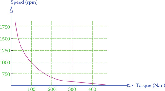
Figure P7.1 Problem 1.
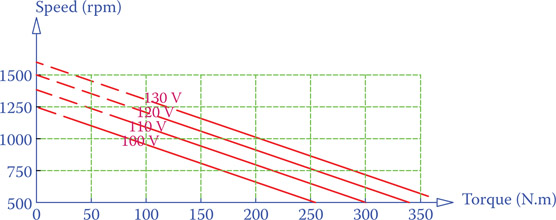
Figure P7.2 Problem 2.
- For running a conveyor a DC motor is employed through a gearbox. For the maximum load on the conveyor, 100 hp of power is required. The gearbox has an efficiency of 90 percent and the efficiency of the conveyor cannot go below 80 percent. What is the required output power from the motor?
- What must the rated power of a motor in kW be in order to run the conveyor in Problem 4 if its efficiency is 92 percent?
- What is the total efficiency of the conveyor system in Problem 4?
- A lift in a wind turbine is used at an average rate of 55 hours per year. There are two options to replace the damaged original motor that provided 2 hp to the lift. One has an efficiency of 70%, and the other has an efficiency of 92%. Calculate the difference in the annual energy consumption of the two motors.