
5
Voltage, Current, and Power
OBJECTIVES: After studying this chapter, you will be able to
- Describe what the main entities of electric flow are
- Explain how current is measured
- Explain how electric voltage is measured
- Define the units of measure for current and voltage
- Know what an ammeter is
- Know what an ohmmeter is
- Know what a voltmeter is
- Describe a multimeter and its use
- Measure the voltage and current in an electric circuit
- Use an ohmmeter to measure the resistance of a resistor or part of a circuit
- Use an ohmmeter for testing capacitors and inductors
- Explain the factors defining electric power
- Explain the importance of each factor
- Perform calculations for basic circuits
- Calculate energy consumption of simple devices
New terms: Ammeter, coulomb, digital multimeter (DMM), electric power, galvanometer, multimeter, Ohm’s law, ohmmeter, voltmeter
5.1 Introduction
Practical understanding of electricity and its usage starts with a good comprehension of the meaning of electric current, electric voltage, and electric power, and the relationships between them. In this chapter these terms are defined, and before going further on, make sure that you have a clear understanding of the meaning of these terms and what they represent. At a practical level, one does not measure electric flow by either counting electrons or caring about what happens to the electrons. The tools used to measure electricity entities are graduated and calibrated in terms of units that are more appropriate for use rather than dealing with individual electrons and their electric charge.
In Chapter 4 we discussed electric current, voltage, and their unit of measure. In this chapter we will discuss how they must be measured in a circuit. As well, we will discuss their relationships with electric power. Understanding of power is quite important, because in many devices it is the power that determines or dictates other quantities.
5.2 Electric Current
In Chapter 4 we discussed that the electric current is a measure of the rate of flow (i.e., how many per second) of electrons. In fact, electric current is the rate of the electric charge of those electrons, because we are concerned about the electric charge, not the numbers, corresponding to electrons. If 6.241 × 10¹⁸ electrons move through a wire in 1 sec (i.e., if these many electrons pass a given cross section of a wire during a 1 sec period), the electric current is 1 amp (1 A). The amount of electric charge corresponding to this number (6.241 × 10¹⁸) of electrons is called 1 coulomb. Thus, we may say a flow of 1 coulomb electricity in 1 sec is 1 A.
Coulomb: Measure of the amount of electricity equal to the electric charge of 6.241 × 10¹⁸ number of electrons.
For these many electrons to move, it is not necessary that their speed be high. It is the volume that counts more, because it is the amount of electric charge that is important. The speed of electrons does not play any role in electrical current, although electricity travels fast, close to the speed of light. The reason for electricity to move very fast is the simultaneous transfer of electric charge along a conductor. In fact, from a mechanics view, electrons cannot go very fast, because although very tiny, they still have mass and follow the rules of motion.
Yet you may not get a tangible feeling for how much 1 A of current is. This will gradually become clearer for you as we continue this discussion. Consider a lightbulb at home; on these, “110 V, 100 W” is written. See how bright (and hot) the filament is when it is connected to electricity. One amp current is around the electric flow rate giving that much heat and intensity to that lightbulb. To see how much it affects a human body, refer to Table 5.1, which shows that even a current of 0.5 A kills a person in less than a second if it passes through the heart. Note that the numbers in the table are in mA (1/1000th of amp).
The fuse box at many homes in North America has a capacity of 100 A. That means it is possible to have a maximum current of 100 A at home. Each regular switch at home is capable of carrying 15 A. From these numbers you can imagine what can happen if you touch the wires.
Table 5.1 Effect of Electric Current through Human Body
| Current (mA) | Effect |
| Less than 1 | No sensation |
| Less than 3 | Mild sensation and possible sudden shock |
| 3–10 | Painful shock, let go current for most of people |
| 10–15 | Local muscle contraction, hands freeze to the conductor for some people |
| 15–50 | Loss of muscle control, freezing to the conductor, burns |
| 50–100 | Difficulty breathing, collapse, and unconsciousness; death for prolonged contact |
| 100–200 | Heart problem (ventricular fibrillation), and death if more than 1/4 sec |
| Over 200 | Clamping action of the heart, respiratory paralysis, death if current is not stopped |
5.3 Electric Voltage
Voltage is the electric potential that causes electrons to move around a closed circuit. Volt is the unit of measure for voltage. Volt is defined as the value of the potential difference for which the energy of one coulomb of electric charge (i.e., the charge of 6.241 × 10¹⁸ electrons) is one joule. Joule is a unit for measuring energy. This official definition of volt may not be much help to understand how much 1 V is. A better understating is possible by considering that each small dry battery you use in your battery-operated devices is 1.5 V, the car battery is 12 V, and the electricity at home is around 115 V. Also, lightning during a thunder storm has millions of volts.
You can touch the two sides of a small battery (1.5 V) without any fear, while you might be cautious about doing the same for a car battery. You should not touch the wires (if bare) at home, because if the voltage there does not kill, it definitely causes injuries and gives a disturbing shock. Similarly, higher voltages are more dangerous; lightning is a high-intensity voltage that if directly hits someone, there is no hope for survival.
Although Table 5.1 shows that the intensity of an injury from electricity depends on the current, as we will see in Section 5.4, the more voltage there is, the more the corresponding current. As a result, the intensity of an electric shock depends on its voltage, and therefore the higher the voltage, the more dangerous it is.
5.4 Ohm’s Law: Relationship between Voltage, Current, and Load Resistance
Ohm’s law is probably the most fundamental as well as important relationship that defines the relationship between voltage and current in a circuit. Try to master the meaning of Ohm’s law before continuing any further.
Ohm’s law: One of the most important laws of electric circuits: relationship between voltage across a component, the current in the component and the electric resistance exhibited by the component to the flow of electricity. For a simple resistor it is V = RI.
Ohm’s law states that if the current in a resistor with a resistance R is I, then the voltage across the resistor (the voltage between the two ends of the resistor) is V, such that
| (5.1) |
where R is in ohm, I is in amp, and V is in volt.
This law also implies that if a voltage of V volt is applied to a resistance of R ohm, then the current is I ampere; that is, the current, voltage, and resistance between two points are always related to each other.
Example 5.1
A lightbulb filament and the wires connecting it to a 12 V battery altogether have a resistance of 5 Ω. Find the current is in the lightbulb filament?
Substituting for the voltage and the resistance in Equation 5.1 leads to
12 = 5 × I
I = 12 ÷ 5 = 2.4 A
Example 5.2
If the same lightbulb as in Example 5.1 is connected to a 1.5 V battery, what is the current?
Solution
Resistance of the lightbulb does not change, because it is the physical property of the metallic wires involved. Thus,
I = 1.5 ÷ 5 = 0.3 A
Note, however, that when a filament is warmed and its temperature has changed, its resistance also changes. Here, for simplicity, we have assumed that the change in temperature is not high enough to affect the resistance.
There are other meanings embedded in Ohm’s law, which we need to pay attention to.
- The relationship between the voltage across a resistor and the current through that resistor is linear. That is, if the voltage doubles, the current doubles, too.
- By the same token, if the resistance of the resistor does not change, then, if the voltage drops in value (decreases), the current also decreases. Similarly, if the voltage increases, the current increases.
- For a constant resistor, if the voltage across it remains unchanged, the current through it remains unchanged. Alternatively, if the current through the resistor does not change, it implies that the voltage across it has not changed.
Note that it is always the voltage applied to a resistor that determines how much the current through the resistor is.
In conjunction with Equation 5.1 we have the following equations that determine current in terms of the voltage and resistance and the resistance in terms of the voltage and the current:
| (5.2) |
| (5.3) |
It is always the voltage applied to a resistor that determines how much the current through the resistor is.
Example 5.3
A resistive element (has only resistance) has a resistance of 50 Ω and is connected to 120 V. If as a result of the generated heat the resistance of the element increases by 10 percent, what current is in the element?
Solution
Initial current in the element is
120 ÷ 50 = 2.4 A
After the element is heated its resistance increases by 10 percent and changes to
I = 120 ÷ 55 = 2.18 Ω
Example 5.4
While the resistive element in the previous example is connected to the 120 V, the voltage changes to 130 V; determine the new current in the element.
Solution
Change in the voltage is relatively small, and it does not affect the resistance of the element. Thus, the new current is
130 ÷ 55 = 2.36 Ω
Example 5.5
When a lightbulb is connected to 120 V supply, it lights up and the current is 0.5 A. If the applied voltage is 220 V instead, what is the current?
Solution
Although for this problem one can numerically find a value for the new current, because the voltage is almost doubled, the physical lightbulb cannot withstand the higher current and its filament will blow.
5.5 Measuring Electric Current
Any electric circuit has a current in it based on the components in the circuit and based on the voltage of its source. Often, it is necessary to measure the current in a circuit for diagnosing problems and repairs. For measuring current we use an ammeter, a device directly graduated in amps and decimal fractions of amp. To measure current in a circuit, an ammeter must be inserted inside the circuit; that is, it must become part of the loop forming the circuit. Figure 5.1 shows that for measuring the current in a circuit you need to open the circuit at one (appropriate) point. Then you connect the two leads of the meter to the open ends of the circuit. In this way the ammeter integrates to the loop and becomes part of the circuit. See Figure 5.2.
Ammeter: Device to measure electric current.
To measure current in a circuit, an ammeter must be inserted inside the circuit. The circuit must be opened for this purpose.
For measuring current one can use an ammeter, which measures the electric current only, or use a multimeter. A multimeter is a multipurpose device that can measure current in addition to voltage and resistance. It has the capability to measure additional entities, such as capacitance and frequency. In circuit schematics a circle with a letter “A” in it represents an ammeter, as shown in Figure 5.1. Similarly, a circle with a letter “V” in it represents a voltmeter, which measures voltage. Note that all the components (including the source) and wires in a single circuit (one loop only) have the same current. In Chapter 6 we will discuss multiloop circuits.
Multimeter: Device for electrical measurements with selectable switches to function as voltmeter, ohmmeter, and ammeter, and some more capabilities (all in the same unit).
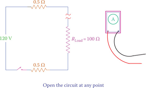
Figure 5.1
Step 1 for measuring the current in a circuit.
Because in DC electricity current has one direction and in AC electricity current direction constantly changes, measuring current in AC and DC is not done by the same ammeter. For DC a DC meter must be used. In multimeters switching from AC meter to DC and from current to voltage and so on can be done using a selector switch with which one selects the desired choice. In measuring DC current the red lead of the meter must be connected to the positive side and the black lead to the negative side. If the leads are switched, the reading will be negative. (The needle is forced to turn to left in an analog device.) In some ammeters (not multimeters) with a needle the zero point is in the middle and the motion of the needle indicates both positive and negative readings. This is helpful for the circuits in which current can be either positive or negative.

Figure 5.2
Step 2 for measuring the current in a circuit.
5.6 Measuring Electric Voltage
Because voltage is the potential difference between two points, to measure voltage, the two leads of a voltmeter must be connected to those points. Pay attention for measuring voltage; you should not open the circuit. Whereas for measuring current, one must open the circuit. In Figure 5.3 we need to measure the voltage across the load. Thus, the voltmeter is connected at points A and B so that the load is between points A and B (Figure 5.4). The measured value is the voltage applied to the load. A voltmeter, in fact, measures the voltage difference between two points.
Voltmeter: Electrical instrument to measure electric voltage.
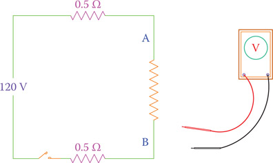
Figure 5.3
Use a voltmeter to measure voltage between two points.
Note that, whereas in a single (one loop) circuit there is only one current, there are various voltages depending on the number of components in the circuit and where the measurement is made. For instance, in Figure 5.5 there is a 100 Ω load and two 0.5 Ω wires connecting the load to the 120 V power supply. We may measure the voltage between each pair of points A, B, C, D, and E; for example, A-B, A-D, B-C, B-E, and so on. The measurement across the source shows the source voltage. Note that in Figure 5.5 all the points A to E are selected at a graphically suitable point in the line connecting two elements together. Any other point on each line denotes the same point of the circuit.
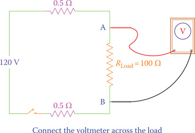
Figure 5.4
Measurement of voltage across two points.
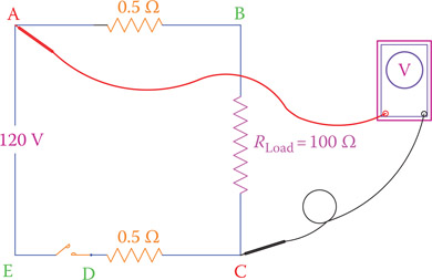
Figure 5.5
There are numerous voltages between various points in any circuit.
In DC electricity, voltage measurement shows the polarity, too. So, if the positions of the leads of a meter are swapped, in a digital meter the reading will appear with a negative sign, but in an analog meter the reading cannot be done because the needle is forced to move to the left.
A voltmeter measures the voltage difference between two points by connecting the meter leads to those points.
Example 5.6
In the circuit shown in Figure 5.6, measurement of the voltage across R2 shows a value of 75 V and a measure of the current in the circuit shows a value of 0.68 A. What is the value of the resistor R2?
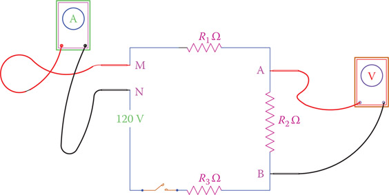
Figure 5.6
Circuit of Example 5.6.
Pay special attention to Figure 5.6 and the way the voltmeter and the ammeter are used for measuring voltage and current. The voltage for R2 must be measured across R2, say between points A and B, but the current can be measured at any point where the circuit is opened and the ammeter is inserted in it.
In any measurement, care must be taken that all the connections are clean and tight. This is especially true for the leads of a handheld meter. Make sure that you firmly hold the leads against the contact points. Otherwise, mistakes in readings are possible.
For any measurement, make sure that the measuring leads are firmly held at the contact points.
5.7 Multimeter
A multimeter is a must-have tool for someone working with electricity and electronics. It is always necessary to verify values, to measure voltage, current, and resistance values in a circuit for diagnostic purposes, or to identify a damaged component. A basic multimeter can measure the three basic electric values (i.e., voltage, current, and resistance), but more functions can also be included in a multimeter.
Galvanometer: A device consisting of a needle attached to a coil that can rotate around a pin shaft as a result of an electric current flowing through the coil. The coil behaves also as a spring, limiting the motion of the needle. A galvanometer is used to measure electric current, but the needle position can be graduated for other electric entities, like voltage.
Initially, there are two types of multimeters, analog and digital. Analog multimeters work based on the deflection of a needle from its zero position point. During a measurement one needs to read the correct value just under the needle. The main part of an analog meter is a galvanometer that consists of a small winding. The winding can rotate about a pin, and a needle is attached to it. It also has a spring to return the needle to the home (zero) position. Depending on the intensity of the current through the winding, it deflects from its rest position. Thus, a galvanometer is a current-sensitive device. By making some changes to a galvanometer and adding more components, it can be used as an ammeter, a voltmeter, an ohmmeter, and other measurement devices. The deflection of the needle in an analog meter is always from left to right.
Ohmmeter: Device for measurement of electric resistance.
Figure 5.7 shows a typical analog multimeter. It has a selector rotary switch by which one selects the category and range of values to be measured. Not all the meters are built the same way and have the same range of values and the same number of terminals. More details of the switches and terminals in the multimeter of Figure 5.7 are illustrated in Figure 5.8. In addition to a main selector switch for changing from volt to ohm or amp and selecting their range of values (e.g., 100 mA, 500 mA, 25 V, and 500 V), there is another switch for AC, –DC, and +DC. There are two main terminals for connecting the black (common) and red leads, but additional terminals are used for 10 A current (current larger than 500 mA and up to 10 A), 500 V and 1000 V (higher voltages). For measuring these relatively high values the black lead still goes to the common terminal, but the red lead must be inserted to the appropriate hole.
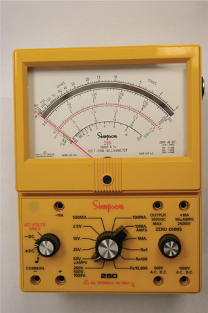
Figure 5.7
Typical analog multimeter.

Figure 5.8
Switches and terminals on an analog multimeter.

Figure 5.9
Various graduations on a typical analog multimeter.
Figure 5.9 illustrates the set of various readings for the multimeter shown in Figure 5.7. As can be understood, these graduations are different, and for one position of the needle, there are various numbers. Each graduation corresponds to one or more selector switch positions. For instance, for a selector switch range of 2.5, 25, and 250 (see Figure 5.8) one must use the graduations ending in one of these numbers, whereas for other selections the numbers are between 0 and 10 (which must be multiplied by a power of 10, accordingly). Also, in the meter shown, the AC values are shown in red, whereas the DC values are in black.
Note that the zero value for ohm measurement (top scale) is to the extreme right (all the other zero values are on the extreme left). This is because a higher resistance value leads to a lower current value (see Ohm’s law in this chapter) and vice versa.
A typical digital multimeter (DMM) is depicted in Figure 5.10. It has a rubber casing that protects it against shocks and scratches. Normally, it is easier to work with a digital multimeter because it directly gives the measured values in numbers. A DMM does not have any moving parts and works based on converting an analog reading to a digital value (analog to digital conversion; see Chapter 22).
Digital multimeter (DMM): A device to measure resistance, current, voltage, and other electrical parameters, in which the reading is automatically adjusted and displayed by 3 or 4 digits, as compared to analog multimeters in which the position of a rotating needle represents a measured value.

Figure 5.10
Typical digital multimeter (DMM).
Similar to an analog multimeter, a DMM has a common terminal to which the black lead is connected and the red lead goes into one of the other terminals, depending on the design of the DMM. In the DMM shown in Figures 5.10 and 5.11 the red terminal is inserted in the hole to the right of the common (com) terminal, but for measuring current (based on its value if it is in the order of amps or much smaller) the other two holes are used. It is always safer to use the higher current terminal first (the one on the left) before using the middle terminal for higher precision. In this way, you do not subject the fine meter to a current much larger than its capacity, which can damage the meter (or blow its fuse).
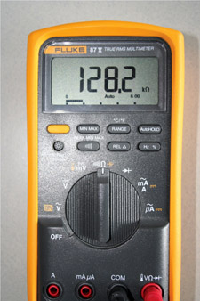
Figure 5.11
Selector switch and the display of a typical DMM.
In the multimeter of Figure 5.10 the switch can be positioned to off, when the meter is not in use, or it can be set for AC voltage, DC voltage, small DC voltage (mV), resistance (ohm, Ω), and current (Ampere A, milliamp mA, and μA micro-amp). There is one more selection for diode (test); we discuss this in Section 14.6. Better DMMs have four digits, as shown in Figure 5.11. Some cheaper DMMs have only three digits. Normally, on the basis of the measured values, the scale is automatically adjusted; for instance, in Figure 5.11 the scale is automatically set to kΩ (appearing on the screen).
5.8 Measuring Resistance
A resistor’s resistance or the resistance of part of a circuit can be measured by an ohmmeter or a multimeter. An ohmmeter or the ohmmeter part of a multimeter works based on measuring the current in a circuit where the item to be measured constitutes the main load of that circuit. Nevertheless, the graduations are made in terms of resistance values, not current values. In this sense, the following differences exist between an ohmmeter and a voltmeter or ammeter:
- An ohmmeter needs a battery to power its circuit, whereas for measuring current or voltage, no battery is needed because there is already a current (when switch is closed).
- Because current is measured, using Ohm’s law, for a smaller resistance, there is a large current and for a larger resistance the current is smaller. This necessitates that the zero reading for resistance (in an analog meter) be at the extreme right side of the scale (the highest current) and the larger resistance values be on the left side.
- Because the ohmmeter battery loses its strength with time, an ohmmeter has a zero adjustment knob that is used to bring the needle to zero reading. It is always necessary to adjust the zero reading before any measurement is made with an analog ohmmeter. This can be done by directly putting together the ends of the two leads, then turn the adjustment knob to bring the needle to zero.
- Measuring resistance must always be performed when the power to a circuit (the resistance of a part of which is to be measured) is turned off. Otherwise, the reading will be erroneous.
An ohmmeter can be used for measuring and verifying the value of any resistor or resistive element. In addition, it can be used for checking the continuity of a circuit to see if any part of a circuit is open or there is any short (two points unnecessarily contacting) in the circuit.
When measuring the resistance of part of a circuit, the power to the circuit must be off.
5.8.1 Checking a Capacitor and an Inductor with an Ohmmeter
An ohmmeter (usually, only analog meters) can also be used to check if a capacitor is good or damaged. If a capacitor is damaged, it either becomes short (when the two plates of the capacitor contact each other) or open (contacts are lost). To check a capacitor, it is connected to an ohmmeter. If it is short, then it shows a high current (near zero resistance) and the meter needle stays at the same point. If it is open, then it shows a very high resistance (the needle stays in the very left side of the meter). If the capacitor is good, the needle of the meter quickly moves to the right and slowly goes back to the left.
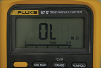
Figure 5.12
Very high value resistance or an open circuit.
In a similar way we can use an ohmmeter to see if an inductor is fine or if it is damaged. A digital or an analog multimeter can be used. Note that in a DMM when the value to be measured is beyond the range of values selected an overload sign will appear on the screen by the letters “OL” as shown in Figure 5.12. Specifically, when measuring resistance, an open circuit (equivalent to a very high resistance measured) is realized if the meter shows OL. An inductor can be shorted or can be open. If after connecting its two ends to an ohmmeter high resistance is noticed, then it is open. A short inductor shows zero resistance. A good inductor shows a small value of resistance but not zero.
5.9 Electric Power
It is always the power in an electric circuit that determines how much energy is going to a device, a system, or a place, and how much that energy costs. A good comprehension of the relationships for electric power, unit of power measurement, and the rules that determine power is very important. You must always bear in mind that for a power source (e.g., generator and battery), power rating implies the maximum power that the device can deliver. For a consumer, (a load) power rating implies the power requirement by the device so that within the desired operating conditions (voltage and current) it can function with good efficiency and with minimum risk of damage. The required power must be available to the device so that it functions properly. If that much power is not provided (by the source, the line, or the power supply), some shortcoming can happen that can lead to damage and failures.
Electric power: Power in the form of electricity and measured by electrical units (power is the amount of work in 1 sec).
Before continuing further, be sure to understand the meaning of power and the difference between power and energy. See the text in this chapter on Energy and Power.
In electricity, power is always obtained from the product of voltage and current. In later chapters we will discuss other factors that come into play and that power (especially in AC) has different categories. For the time being you need to understand that power is proportional to voltage and current. The analogy given in Chapter 4 between electricity and water flow can help you to understand this fact better.
Energy in water depends on both the height and the volume of water. Likewise, the power (energy in one second) in the water depends on the height and the water flow rate. It is obvious that out of the four scenarios shown in Figure 4.14, case c has the largest power. For this case both the current and the voltage have the larger values. As can be seen, both the height (corresponding to voltage in an electric system) and the flow rate of water (corresponding to current) influence the power. If the current does not change but the voltage doubles, the power doubles, and if the voltage does not change but the current doubles, the power doubles. This relationship is
| (5.4) |
where P is in watts, V is in volts, and I is in amps.
Equation 5.4 clearly shows that for the power to be constant (this situation often occurs in practice), if the voltage decreases, then the current must increase or if the current increases, the voltage must decrease. Current increase beyond a rated value is equivalent to overload, which is not desirable.
Example 5.7
Measured current in the filament of a lightbulb when connected to a 12 V battery is 5 A. What is the power consumption of the lightbulb?
Solution
Power can be directly found by the product of the voltage and the current:
P = VI = (12)(5) = 60 W
Energy and Power
“Energy” is the potential to do work, and it can be in different forms, such as electrical energy, nuclear energy, thermal energy (heat), wind energy, and solar energy. “Work” here implies mechanical or other type of work. Mechanical work is, for instance, when a weight is lifted or when an engine drives a car. Mechanical work is more tangible compared to other types of work. For instance, a motor can do mechanical work, but a battery does not directly do mechanical work. However, it can run a motor that does mechanical work; thus, a battery has potential to work. It has electrical energy. Energy can be converted from one form to another. For instance, consider a steam turbine that can do mechanical work. That is, conversion of heat to mechanical energy. In this sense, when an electric kettle heats water, it performs work. It consumes energy and converts it to work.
Energy can be measured, like any other entity, in its appropriate unit(s). Suppose that a machine or device has energy. How much energy does it have? Energy can be measured in terms of heat units like calorie and BTU (British thermal unit), work units, or energy units. The unit for energy is joule, and units for work can be foot-pound and newton-meter. One joule is, in fact, one newton-meter.
In conjunction with energy we have power. We may always ask the question: “If a machine can do a certain amount of work, how long does it take to do it?” For example, how long does it take for a kettle to boil the water in it? The answer to this question stands in power, which is also used for comparison between various energy sources. Power is the amount of work done in 1 sec by a device that can do work. This is the measure of strength of energy sources. For instance, a smaller motor has less power than a larger motor. That is, it can do less work than the larger motor in the same duration of time or, in doing the same work for the smaller motor it takes more time. Similarly, it takes more time for a smaller (less powerful) kettle to boil the same amount of water compared to a larger kettle.
Thus, power is determined from energy divided by time.
Electrical power is normally measured in watt and kilowatt. Energy is sometimes (especially in the case of electrical energy) measured in terms of the unit of power multiplied by the unit of time; that is, watt-second and kilo-watt-hour are used as units of energy.
For almost any device, including lightbulbs, the power is written on the device itself or on a nameplate. In addition, the operating voltage is always shown. For example, on a lightbulb you may see “100 W, 120 V.” This implies that
- Operating voltage of the lightbulb is 120 V. You should not connect this bulb to a voltage that is considerably higher than 120 V; whereas it is generally acceptable if you connect it to 125 V, but if you apply 180 V to this bulb, you will definitely burn it out.
- If connected to 120 V, the power consumed by the lightbulb is 100 W. Moreover, if you connect it to a higher voltage, the power will be more than 100 W, and if the voltage used for the bulb is lower, then the power is lower than 100 W.
Note that physically the lightbulb does not change and it has only a filament in it with certain resistance. The resistance of the filament when it is cold is less than when it is lighted.
Example 5.8
What is the resistance of the filament in a 100 W, 120 V lightbulb?
Solution
The current in the lightbulb filament can be found from Equation 5.4:
100 = (120)(I) → I = 100 ÷ 120 A
From Equation 5.1, however, we have
(R)(100 ÷ 120) = 120 V
This leads to R = 144 Ω.
Example 5.9
What is the power consumption of a 100 W, 120 V lightbulb if it is connected to 110 V?
Solution
No matter to what voltage the lightbulb is connected, its filament does not change. When the lightbulb is connected to 110 V, its filament still gets hot and with good precision we can assume that its resistance stays at 144 Ω (see Example 5.8).
The current due to connecting this lightbulb to 110 V is
I = 110 ÷ 144 = 0.764 A
Thus, the power of the lightbulb is
P = (110)(0.764) = 84 W
It can be clearly seen that if the voltage applied to a lightbulb (or any other device with resistive element) is not the same as its rated voltage, then one cannot expect to obtain the rated power.
Note that if the applied voltage is much smaller than the rated value, then the lightbulb filament is not heated enough and its resistance cannot be assumed to stay the same. Its resistance becomes slightly smaller.
As can be seen from the Ohm’s law and from the relationship for power, there are four interrelated electrical entities for any resistive load: resistance, voltage, current, and power. When any two of these values are known, the other two can be obtained. Equations 5.1 through 5.4 can be combined together to give rise to the formulas for determination of any of the four entities in terms of two other ones. Four of these equations are already given by Equations 5.1 through 5.4:
- Power
(5.5) (5.6) - Current
(5.7) (5.8) - Voltage
(5.9) (5.10) - Resistance
(5.11) (5.12)
All of the Equations 5.1 through 5.12 can be put together in the form of charts shown in Figure 5.13.

Figure 5.13
Summary for the relationships among voltage, current, resistance, and power for (a) inductor and (b) capacitor.
Example 5.10
In a resistive element the current is 4 A and the power consumed by the element is 160 W. What is the resistance of the element? What is the voltage across the element?
Solution
Resistance of the element is found in terms of the power and current. From Equation 5.11 we have
Voltage across the element can be found from either of Equations 5.1, 5.9, or 5.10:
V = (10)(4) = 40 V
Example 5.11
When a voltage of 110 V is applied to a resistor, the power generated in the form of heat is measured to be 60 W. What is the resistance of the resistor?
Solution
We may directly use Equation 5.12:
Note that the power consumed by the resistor converts to heat.
Example 5.12
If the voltage applied to the resistor in Example 5.11 increases by 10 percent, what is the percentage of increase in power?
Increase in voltage is
110 × 0.10 = 11 V
Thus, the new voltage is 121 V. The new power can be found, having the voltage and the resistance, from Equation 5.6:
and the percentage of power increase is
5.10 Measuring Electric Power and Energy
From the fact that power is the product of voltage and current, it is obvious that a watt-meter to measure power must work based on a needle (if analog) or a display (if digital) whose displacement or value is proportional to the values for both the voltage and the current in a circuit. While a watt-meter can be used in panels of electric generators to indicate the instantaneous power, it is normally not used by a technician, and it is not included in the functions of a multimeter.
However, measuring energy is very common for the calculation of electric energy cost. Each house and building is equipped with an electricity meter that measures the consumed electric energy. The basis of such a meter is a circular disk that rotates and causes a series of gears to rotate as in a clock. The speed of rotation of this disk is proportional to the power consumed in a circuit, and the number of revolutions during a period represents the energy consumed during that period.
The unit for measuring power is watt (see the table of units and conversions in Chapter 2). A kilowatt (1000 watts) is a larger unit, and for even larger measures of energy production, megawatt (1,000,000 watt) is a more common unit of power.
Because energy is the product of power and time (see the text on Energy and Power in this chapter), we may write
| (5.13) |
If P is the power in watt and T is the time in second, then E determines energy in joules. It is very common in electricity that a larger unit of energy be employed. If the power is given in kW and time in hr (3600 sec), then the unit of energy is kW-hr (kilowatt-hour). Kilowatt-hour is a unit of energy equivalent to (1000)(3600) = 3,600,000 joule.
A better understanding of kW-hr is possible in the following manner. One kW-hr is the energy consumption of one 100 W lightbulb in 10 hours, or of two 100 W lightbulbs in 5 hours, or ten 100 W lightbulbs in 1 hour.
A 100 W lightbulb is turned on 5 hours per day. Calculate the amount of energy consumed by the lightbulb in a year.
Solution
Number of hours the light is on in a year = (365) (5) = 1825 hr
Energy = (100)(1825) = 182,500 W-hr = 182.5 kW-hr
Example 5.14
If the cost of electricity is 8 cents per kW-hr, what is the cost of electricity used by the lightbulb in Example 5.13?
Solution
Annual cost = (182.5)(0.08) = $14.60
Example 5.15
If the average daily electricity consumption in a household is 4 kW-hr during a given season, what is the monthly cost of electricity if the rate of electricity is 7.5 cents per kW-hr?
Solution
Average monthly consumption = (30)(4) = 120 kW-hr
Cost = (120)(0.075) = $9
Example 5.16
You have a walkway light that remains on during night and turns off during daytime. It uses a 60 W lightbulb. If you change the light bulb with an energy saving bulb, which uses 10 W, how much electric energy would you save if you consider the yearly average night hours to be 11 hr. If the rate of electricity is 8.5 cents per kW-hr, how much money do you save in one year?
5.11 Chapter Summary
- Voltage applied to a circuit and the current in the circuit are not independent.
- If a circuit has resistive load, the higher the load is, the smaller the current is.
- Voltage difference between two points equals the product of the resistance between those points and the current.
- To measure current, an ammeter is used. The circuit must be opened at one point and the ammeter be inserted in the circuit.
- There is only one current value for all components in a single circuit.
- The unit to measure current is ampere (amp), and its symbol is A.
- To measure the voltage difference between two points, a voltmeter must be connected between those points without opening the circuit.
- Voltage difference depends on the points to which the voltmeter is connected.
- The unit to measure voltage is volt, and its symbol is V.
- To measure current and voltage, a circuit must be energized.
- The unit to measure resistance is ohm, and its symbol is the Greek letter Ω (omega).
- For measuring the resistance between two points in a circuit the power must be off.
- A multimeter is a device containing a voltmeter, ammeter, and ohmmeter in one unit. It can have other capabilities (e.g., frequency measurement).
- All meters can be made analog (with a moving needle), or digital, which directly gives the measured value in numbers. Most digital multimeters have four digits. Others have three digits.
- An ohmmeter can be used also for testing a capacitor or an inductor to see if it is damaged.
- Any electric device has a nominal voltage. This voltage is written on the device or its nameplate, together with the device power. This is the voltage that best suits the operation of that device.
- Power of a device depends on the voltage applied to it. If the nominal voltage is applied, power is the nominal power written on the device.
- If the voltage applied to a device is much different from the nominal voltage, the device will be damaged or will not deliver the expected power.
- Power is determined from the product of the applied voltage and current in a device.
- Applied voltage to a device determines its current and, thus, its power. For a load this is the power that the device absorbs from the circuit or the power supply.
- In a source the rated power is the maximum power that it can deliver. For a load the rated power is the amount of power required for functioning of the device.
- Energy is power multiplied by time.
- In electricity the most common unit of energy is kW-hr (kilowatt-hour).
- We pay for electricity based on the amount of energy, normally expressed in kW-hr.
Review Questions
- What are the two main entities associated with electricity?
- What is the unit for measuring current called?
- How is electric current measured, in terms of connecting a meter?
- What is the name of the device with which current is measured?
- When measuring current in a circuit, should the power be on or off?
- What is the name of the device for measuring voltage?
- Explain how you measure voltage between two points.
- What is the name of the unit for measuring voltage?
- What is the difference between potential difference and voltage difference?
- How much do you read/measure if you connect both leads of a voltmeter to the same point in a circuit? Explain why.
- If you have a circuit without any source, how much can you read the voltage between any two points? Explain why.
- What do you use to measure the resistance of a resistor?
- What is the unit for measuring resistance?
- If you have only a voltmeter and an ammeter and you need to measure the value of resistance between two points of a circuit, describe how you can do this.
- If you have an ohmmeter and you need to measure the value of resistance between two points of a circuit, should the power be on or off?
- What is a multimeter?
- What color lead do you connect to the terminal marked “com”?
- In an electric circuit, power is proportional to which two entities?
- If the voltage applied to a lightbulb is lowered, does its power go up or down? Explain.
- If the current in a lightbulb filament goes up, does its brightness go up or down?
- Can you use a multimeter to test if a capacitor is damaged or it is good? If yes, explain with which of the devices in the multimeter.
- What are the two main faults in a damaged capacitor?
- What are the two main faults in a damaged inductor?
Problems
- The heating element of a stove is marked 240 V, 1500 W. How much current do you expect to be flowing through the element when it is connected to 240 V electricity?
- Find the resistance of the heating element in Problem 1.
- If the resistance of a heating element is 40 Ω and it is connected to 240 V, what is the current in the element?
- If the element in Problem 3 carries a current of 5.5 A, what voltage is applied to it?
- The heating element in Problem 1 is connected to 220 V (instead of 240 V). What power does it takes from electric source it is connected to?
- When the element of Problem 1 is connected to 220 V, what is the current in the element?
- If a lightbulb is 100 W, 120 V. When you measure the voltage at home it shows 110 V. What is the power consumption of the lightbulb?
- When you connect the lightbulb in Problem 7 to 110 V, you will not get the full brightness of the lightbulb as when you connect it to 120 V. Approximately, how much less percent is the brightness?
- You have bought a kettle in Europe. On its nameplate it says “1500 W, 220 V.” Suppose that when you used it in Europe, it could boil water in 5 min. At your home the electricity voltage is 110 V. At home you connect the kettle to electricity and it does not boil the same amount of water in 5 min. Explain why.
- Approximately how long do you expect that it should take for the kettle in Problem 9 to bring the water to boil at your home?
- What is the resistance of the element in the kettle of Problem 9?
- If you want to change the element of your kettle (in Problem 9) so that it boils water in 5 min, what size resistance should you look for (assuming it is available)?
Project
Find an electric device at home or at a store. Write down the information provided on its case, on its nameplate, or on the device itself. How much of this information do you understand? Discuss the information in the class.