
10
Transformers
OBJECTIVES: After studying this chapter, you will be able to
- Describe the principles of operation of all transformers
- Define the terms step-up and step-down
- Select a transformer power rating based on the loads to be powered
- Understand practical concerns when using transformers
- Explain the differences and similarities between single-phase and three-phase transformers
- Understand and use terms employed for transformers
- Understand the four different configurations for connecting three-phase transformers
- Calculate efficiency of a transformer based on its daily usage data
- Explain familiar tests for measuring transformer data
- Use the data from tests to determine transformer losses
New terms: All-day efficiency, autotransformer, copper loss, core loss, core loss current, core-type transformer, energy efficiency, hysteresis, ideal transformer, isolation transformer, leakage (in transformer), magnetizing current, open-circuit test, pad mount (transformer), pole mount, shell-type transformer, short-circuit test, step-down transformer, step-up transformer, tertiary, tertiary winding, transformer percent impedance, turns ratio, voltage regulation, volts per turn, zigzag transformer
10.1 Introduction
One of the salient features of AC electricity is that it can be transformed easily and in a relatively cheap way compared to DC electricity. Without this feature, electricity usage would be very limited.
As we have discussed so far, there are four parameters associated with AC electricity, voltage, current, power, and frequency. The main function of a transformer is changing the voltage of AC electricity, either increasing or decreasing it. Nevertheless, as we will see in this chapter, because of power balance, as a result of voltage change current also undergoes a change. The only parameter that is not affected is the frequency.
The applications of transformer are plentiful, and transformers of all sizes are made. Here size can refer to the physical size, but it can also reflect the power because the larger the power capacity of a transformer, the larger it is in size. For example, a transformer for powering a halogen lightbulb (halogen lightbulbs use 12 V electricity) is small and can handle about 20 W of power (their rating is about 20 W). The transformer of a 2 MW wind turbine must be capable of handling 2 MW of power, and it is considerably larger.
10.2 An Illustrative Example
We start this chapter with an example, which illustrates the importance and the effect of changing voltage, particularly for power transmission. The importance of a transformer is more pronounced for high powers, although at low-power level, there are millions of small transformers in all household and industrial products. This is a simple example but conveys the importance of using transformers.
Example 10.1
A 100 hp load (e.g., a three-phase motor) is fed by a 400 V line. The load is delta connected to the line, and its power factor is 0.8. If the resistance of each of the three wires connecting the load to the mains is 0.5 Ω, (1) find the voltage drop and the power loss of the wires and (2) compare these values with the case if the voltage was 4000 V.
Solution
On the basis of the relationships for power in a three-phase system (see Section 9.5.2), the current in the line can be found.
-
For V = 400 V,
For this current the voltage drop in the line is (by Ohm’s law)
Vdrop = ΔV = (0.5)(134.6) = 67.3 V
and the power used in the three wires is
Ploss = (3)(0.5)(134.62 = 27,173.6 W
-
For V = 4000 V
For this current the voltage drop in the line is (by Ohm’s law)
Vdrop = ΔV = (0.5)(13.46) = 6.73 V
and the power used in the three wires is
Ploss = (3)(0.5)(13.462 = 271.74 W
It can be observed that the current in the 400 V line is so high that it leads to a voltage drop of 67.3 V, which implies that the voltage in the line must be 467.3 V so that the load gets 400 V; otherwise, the voltage at the load would be smaller than 400 V. Moreover, a large amount of energy is lost in the form of heat, which is undesirable.
The comparison of the results for 4000 V illustrates that in this case the voltage drop is only 6.73 V, and the power loss in the line is under 272 W.
It is very important that the voltage drop and the consumed energy by the feeding lines be minimized by using the proper voltage for transmission of electricity, and this is done by transformers.
10.3 Single-Phase Transformer
In the same way that single-phase AC and three-phase AC are different, although both are alternating current electricity, single-phase and three-phase transformers cannot be interchanged. Nevertheless, most of what can be said for single-phase transformers is later on extended to three-phase transformers because they work based on the same principle.
Transformers work based on the mutual induction between two windings. As we have learned, when electricity is applied to a coil a magnetic field is developed (see Section 7.2). Because in AC the voltage (and thus the current) continuously alters, the resulting magnetic field is variable. However, if a coil is placed in a varying magnetic field, it is similar to a wire that moves in a magnetic field; then a voltage is induced in it.
In what follows in this section, everything said mainly refers to a single-phase transformer, though for the sake of simplicity the term “single phase” is not repeated.
10.3.1 Transformer Fundamental Construction
Core-type transformer: Category for the construction of a transformer in which the core has the shape of a rectangular frame, and the windings are normally on the opposite sides of the rectangle.

Figure 10.1
Basic structure of a transformer (core type). (a) Schematics. (b) Pictorial representation.
In the simplest form a transformer is made up of two windings which share a common core. The core must be closed and its material be a ferromagnetic metal; it can be of various shapes, but the shape does not play a significant role. Some shapes are preferable to the others, either because of manufacturing or because they can result in a better performance. The most common shapes for a core are rectangular and circular. From the manufacturing viewpoint, a rectangular shape is easier to work with. Figure 10.1 shows a transformer with a rectangular core. In this configuration, called a core-type transformer, the two windings are on the opposite sides (legs) of the core. This is not necessary, and both can be on the same leg. In fact, most of the small transformers have a core as shown in Figure 10.2, and both windings are placed—usually side by side—on the middle leg. This is a called a shell-type transformer.
Shell-type transformer: Category for the construction of a transformer in which the core has the shape of a figure 8 (i.e., with a bridge in the middle of a rectangular frame).
The two windings are called “primary” and “secondary,” depending on their role. The primary winding is connected to the voltage that we want to change. The secondary winding provides the required voltage. In other words, the primary winding is connected to the input voltage and the secondary winding is the output and is connected to the output circuitry. To show a transformer in a circuit, the transformer symbol is used, as depicted in Figure 10.3.
If the primary winding has more turns than the secondary winding, the transformer decreases the voltage and it is a step-down transformer. If the primary winding has fewer turns than the secondary winding, the output voltage is higher than the input voltage and the transformer is called a step-up transformer. The numbers of wire turns in the primary and secondary windings are represented by N1 and N2, respectively.
Step-down transformer: Transformer with secondary winding having fewer turns than the primary winding, thus decreasing voltage.
Step-up transformer: Transformer with secondary winding having more turns than the primary winding, thus increasing voltage.
For a step-down transformer, N1 > N2 and V1 > V2.
For a step-up transformer, N1 < N2 and V1 < V2.
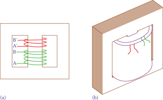
Figure 10.2
Most of transformers have a shell-type structure. (a) Schematics of a shell-type transformer. (b) Pictorial view.
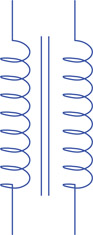
Figure 10.3
Symbol for a transformer.

Figure 10.4
Two possible ways of winding a wire around a core.

Figure 10.5
Number of turns N, voltage V and current I in the primary and secondary circuits of a transformer.
Note that a wire can be wound around a core in two directions, as shown in Figure 10.4. As a result, depending on the directions of both windings in a transformer, at a given instant and compared to the primary voltage, the current in the secondary winding can be in one or the opposite direction. In other words, the secondary voltage can be in phase with the primary voltage, or it can be 180° out of phase with it. It is, therefore, important to pay attention to the direction of turns in the winding of a transformer. In Figure 10.2, for instance, both windings have the same direction. To show the polarity in the drawings of transformer circuits, a dot is put at one side of each winding indication the phase relationship, illustrating also the relative directions of the primary and secondary currents. This is indicated in Figure 10.5. Thus, for example, considering a sinusoidal waveform, when the side with a dot in the primary winding is at its maximum value the side with a dot in the secondary winding is at its maximum value. In practice, the terminals are marked by letters such as H and X on the primary and secondary referring to the dot side to indicate this polarity. Figure 10.5 also indicates the number of turns N, the voltage V, and the current I and its direction for a given instant, identified by subscripts 1 and 2 for the primary and the secondary circuits, respectively.
10.3.2 Multi-Output Transformers
It is possible to have multiple secondary windings on the same transformer. This provides various voltages from one source voltage, thus reducing the cost and space. This is very common in electronic devices such as a television that need various voltages for their operation. This is done in very small transformers. In larger transformers and three-phase transformers it is not normally necessary to have multiple voltages. Figure 10.6 shows the schematics of a multi-output transformer.
Figure 10.7 shows a very small, 20 W, transformer. It converts 120 V into 6 and 12 V. In this sense, it is a two-output transformer. A 4 kVA industrial transformer is shown in Figure 10.8.

Figure 10.6
Multi-output transformer.
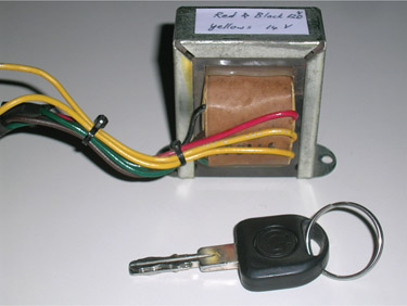
Figure 10.7
A 20 W single-phase transformer.
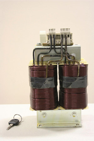
Figure 10.8
A 4 kVA single-phase transformer.
10.4 Ideal Transformer
In all transformers, one phase or three phase, the primary winding gets energy from the mains and the secondary winding is connected to the load(s). If the secondary circuit is turned off by a switch, there is no load on the secondary winding. Nevertheless, the primary winding is still connected to electricity and forms a closed circuit. In this case the primary winding behaves as a coil with a core; a current flows through it that (1) warms the winding and (2) warms the core as a result of eddy currents and hysteresis.
Eddy current is a local movement of electrons in a ferromagnetic material when placed in a magnetic field. In a solid piece of iron or other ferromagnetic metal, there can be many local circuits of eddy current in various directions, depending on the variation of the magnetic field. This unwanted current not only warms up a core, it consumes energy and also affects the magnetic property of the core metal.
To reduce the eddy currents and its effects, all the core materials of transformers and motors are made up of laminated metal. Each lamination has a layer of paint or nonconductive wax on it so that it is electrically isolated from its neighbors. In this way, eddy currents are limited to those only inside of one laminated metal. Figure 10.9 shows what a laminated metal looks like. This greatly reduces the amount of energy loss by eddy current and the resulting heat. Nevertheless, eddy currents cannot be entirely stopped and the associated energy loss cannot be reduced to zero. There are other types of loss in transformers, such as hysteresis and mechanical loss (energy changed to noise). But these are relatively smaller than eddy current loss in a well-designed transformer.
The loss due to the current in the winding(s) is called copper loss, and the losses due to eddy currents, hysteresis, and so on are referred to as core loss because they occur in the transformer core, and they are independent of how much the current is (but they increase as frequency goes up).
Copper loss: Amount of power loss in a transformer that corresponds to the resistance of the wire winding and it depends on the load current (the percentage of loading).
Core loss: Amount of power loss in a transformer that corresponds to the quality of design and core material and is independent of the load current.
To develop the electrical relationships between the primary and secondary transformers, all losses are assumed to be zero. This simplifies the relationships and facilitates developing the pertinent equations. Such an assumed transformer in which all the losses are neglected is called ideal transformer.
Ideal transformer: When in a transformer all the losses are assumed to be zero and, as a result, input power equals output power.

Figure 10.9
Laminated metal for transformers and motors.
In an ideal transformer the output power and the input power are equal. That is, all power received by the primary winding is delivered to the secondary winding.
In dealing with any device, including transformers, one needs to bear in mind that it is always the load that determines how much power is required.
In an ideal transformer all the losses are assumed to be zero. As a result, the power in the primary side is equal to the secondary side power.
10.4.1 Voltage Relationship
Referring to Figure 10.5, the primary winding is connected to a supply voltage V1 and the secondary voltage V2 is applied to a load. In general, a load can be resistive, inductive, capacitive, or a combination of these. A current I2 will flow in the secondary winding. On the basis of this current the primary winding curries a current I1.
The relationship between the primary and secondary voltages is based on the ratio of the number of turns in the primary and secondary windings. The turns ratio in a transformer is the ratio of turns in the primary winding to that of the secondary winding and is denoted by a.
Turns ratio: Ratio of number of turns in the secondary and primary windings of a transformer.
The following equation is the fundamental relationship for an ideal transformer:
| (10.1) |
where V1 and V2 are the primary and secondary voltages, respectively; N1 and N2 are the number of turns in the primary and secondary windings, and a is the turns ratio. For most transformers the turns ratio is fixed and cannot change. When a > 1, the secondary voltage is smaller than the primary voltage, thus a step-down transformer. When a < 1, the secondary voltage is larger than the primary voltage and the transformer is a step-up transformer.
Equation 10.1 shows that a transformer with a given turns ratio, for instance 10, can divide its input voltage by 10 at the secondary winding. This transformer can theoretically also multiply its input voltage by 10. For instance, if the side with the lower number of turns is connected to 120 V, the secondary winding has 1200 V at its terminals. This implies an important and serious issue: in working with a transformer, special care must be taken for its correct connection to the source and loads. Wrong connection can easily lead to damage and injuries.
In a step-up transformer the secondary voltage is higher than the primary voltage. In a step-down transformer it is the reverse.
Take note that although theoretically one can connect a transformer for stepping up or stepping down a given voltage, and there are transformers designed for working both ways, in practice, design considerations such as wire thickness and transformer power rating determine the limitation for the use of a transformer. A transformer cannot necessarily be connected to any arbitrary voltage or in an arbitrary fashion.
In working with a transformer, special care must be taken for correct connection of its primary and secondary to the outside circuits.
Example 10.2
The primary winding of a transformer has 1000 turns. If this transformer is to be used for changing 120 V input to 24 V output, how many turns are needed for the secondary winding?
In using transformers, often the turns ratio is mentioned in the form of a:1 (a to 1) or 1:a (1 to a). For example, in a 2:1 transformer the primary voltage is twice the secondary voltage.
In conjunction with Equation 10.1 one can understand that in a transformer the ratio
is a constant. This constant is called volts per turn and determines how many volts there are per each turn of either the primary or the secondary winding. The use of this constant is in the design stage of a transformer.
Volts per turn: Number indicating the value of volts for each turn of winding in a transformer. This value can be obtained from either the primary side values or the secondary values by dividing the voltage by the number of turns.
10.4.2 Current Relationship
The relationship between the primary and secondary currents for an ideal transformer is based on the power relationship; that is, the power in the primary side is equal to the power consumed in the secondary side. Always, in AC electricity the consumed power refers to the apparent power, the product of voltage and current. Writing
S = V1I1 = V2I2
leads to
| (10.2) |
This equation also implies that in a transformer the side with the higher voltage has a smaller current and vice versa. The secondary current I2 can always be found from the secondary voltage and the load impedance connected to the secondary. Having the current in the secondary, then the current I1 in the primary can be found. This is for an ideal transformer, and I1 represents the current in the primary due to the load only. If there is no load connected to the secondary side, this current is zero, too. In other words, in an ideal transformer the current I1 as obtained from Equation 10.2 does not include the no-load current and the core loss currents (due to eddy currents in the core, mentioned earlier) that exist in a real transformer.
Because the current in the secondary and primary windings are not the same, the wire sizes for the two windings are not the same. The current in the winding with the lower number of turns is always higher than the current in the other winding. Thus, the lower voltage (higher current) side always has a thicker wire than the higher voltage (lower current) side. This can be a good way to judge the connections if in doubt.
For a step-down transformer, secondary current is higher and the winding wire is thicker than that of the primary winding.
Example 10.3
A step-down transformer is used to change 220 to 110 V. If a resistive load consuming 500 W is connected to the 110 V side, what is the current due to this load in the secondary and primary windings?
Solution
Because this is a 2:1 transformer, current in the primary winding is half of the current in the secondary winding. From the power of the load and the voltage in the secondary side the current I2 can be found
from which the current in the primary side follows
I1 = (0.5)(4.54) = 2.27 A
10.5 Autotransformer and Isolation Transformer
Autotransformers and isolation transformers are made for both single-phase and three-phase applications. They are not different in principle from other transformers but are meant for a special purpose.
10.5.1 Autotransformer
Autotransformer: Transformer with only one winding per phase (instead of two). Primary and secondary windings are part of the same wire winding.
An autotransformer has only one winding with one or more taps that serves for both primary and secondary windings. In this way a part of the winding is shared between the primary and secondary of the transformer. Secondary winding can be selectable by taps or a slider, which provides an adjustable voltage. Application of such a transformer is numerous when a voltage must be only slightly changed. For example, normally toward the end of a distribution line there is a noticeable voltage drop. To compensate for this voltage drop, the line voltage must be raised to its nominal value. Consider the houses at the end of a street where the line voltage must be 120 V. If the voltage has dropped to 105 V, then it is necessary to increase the voltage by 15 V to bring it to the nominal level. In such a case an autotransformer is used.
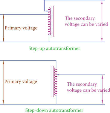
Figure 10.10
Principle of operation of an autotransformer.
The winding is tapped at the proper point for the desired voltage ratio. An autotransformer can be used for both stepping up and stepping down voltage. Figure 10.10 shows the concept for a single-phase autotransformer.
Small autotransformers can often be used when a variable voltage is required. This is obtained by a slider that for the secondary voltage connects to different points on the winding. In the larger three-phase transformers, there is a tap changer that moves from one connection to the other for regulating the voltage, as required. In these transformers this operation is in the form of make and break (meaning that a new connection is made before the previous connection is removed). Otherwise, sparking occurs under high current, which is undesirable and unsafe. A small single-phase autotransformer is depicted in Figure 10.11.
Note that in an autotransformer the primary and secondary currents flow through the same winding. But the direction of the currents at each instant is such that the primary and secondary currents do not add together for the common part of the winding.
10.5.2 Isolation Transformer
Sometimes in electrical applications it is necessary that a device be isolated from the rest of the circuit feeding it. That is, the device receives a voltage while not directly in parallel with other devices. In such a case an isolation transformer is employed. The schematic of an isolation transformer is shown in Figure 10.12. In an isolation transformer the number of turns of the primary and secondary windings is the same. As a result, the secondary voltage is the same as the primary voltage. Nevertheless, if by a fault in the primary circuit the current suddenly jumps up, the device connected to the secondary side is not affected. The isolation transformer, thus, is used when a device must be protected from damage.

Figure 10.11
A small autotransformer.

Figure 10.12
Insulation transformer schematics.
Isolation transformer: Transformer with the same number of turns in the primary and secondary windings, thus not changing voltage. Its purpose is only to protect a device from possible high currents in the primary side by isolating it from being directly connected to the mains.
10.6 Transformer Mounting
While small transformers used with a device (such as a television) are mounted inside the device, large size transformers are stand-alone and must be somehow supported where they stand. In this sense, transformers are divided into pad mount and pole mount. As the name implies, a pad mount transformer is mounted on a platform on a horizontal surface, whereas a pole mount transformer is more suitable for mounting on the top of distribution line poles.
Pad mount (transformer): Transformer that is mounted on a flat surface (a flat slab) as opposed to those which are designed to be mounted on an electric pole (pole mount).
Pole mount: Type of transformer which is suitable for mounting on an electric pole.
Figure 10.13 depicts a pad mount transformer of a wind turbine. The figure shows the transformer radiators for cooling the oil inside which the body of the transformer resides. Figure 10.14 shows three pole mount transformers.
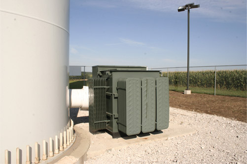
Figure 10.13
A wind turbine pad mount transformer.
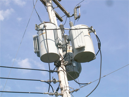
Figure 10.14
Pole mount transformers.
10.7 Three-Phase Transformers
For three-phase electricity transformation it is possible to use three separate but similar single-phase transformers, or a three-phase transformer (see both cases in Figures 10.13 and 10.14). A three-phase transformer is more compact and more efficient. The single core in a three-phase transformer can have various forms by combining the cores of single-phase transformers. Figure 10.15 shows the more common core forms. In practice, however, in addition to the basic structure, there are other concerns to be taken into account in order to increase the efficiency (see Section 10.9) and protection of a transformer. A cutaway of a medium-sized, three-phase transformer is shown in Figure 10.16.
In a three-phase transformer the three primary windings are connected to the supply voltage as a three-phase load for the power supply circuit; so, they can have star or delta (Y or Δ) connection. Independent of how the primary side is connected, the secondary windings can be connected together forming either a star or a delta. This implies that there are four ways that a three-phase transformer can be used in a circuit. The four ways are referred to as delta-delta, delta-star, star-delta, and star-star; these are shown in Figure 10.17. Thus, the voltage ratio not only depends on the turn ratio of the windings but also on what way the connections are made.
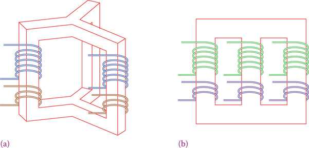
Figure 10.15
Basic structure of three-phase transformer. Transformer core structure can be as in (a) or in (b).

Figure 10.16
Construction of a three-phase transformer. (Courtesy of SPX Transformer Solutions, Inc. All rights reserved.)
The choice of configuration depends on the application. A delta-delta configuration is used in many industrial (factories and manufacturing) applications. In electricity transmission that might not be the best choice, depending on various other factors. In practice, there are other concerns that are taken into account. Grounding for faults and the existence or excitation of harmonics are among these issues.
If the higher voltage has delta connection and the lower voltage side is connected in wye and has a ground, this is referred to delta high-groundedwye low. This is the standard configuration used by utilities for transmission and distribution. Some (large) transformers in power generation and distribution have auxiliary windings in addition to the main windings. This smaller winding is referred to as tertiary. In the case that the two main windings are wye connected because both provide a reference point for grounding, the tertiary winding is delta connected, and its purpose is to provide a path for the third harmonics. The purpose of the tertiary winding can be for providing a neutral point for grounding; for example, when both main windings are delta connected. A Y-connected tertiary then provides a reference for grounding. Another way of generating a neutral point for grounding is using a zigzag transformer (see Appendix C).

Figure 10.17
Four different configurations for primary and secondary windings connection in a three-phase transformer. (a) Delta − delta. (b) Wye − delta. (c) Delta − wye. (d) Wye − wye.
Tertiary winding: Auxiliary winding in a three-phase transformer used for providing a grounding point or for making a path for flow of certain currents, depending on the case.
Zigzag transformer: Special three-phase transformer in which the primary and secondary windings have the same number of turns and are combined in a particular way such that they cancel the magnetic effect of each other. It can be used for various purposes including fault detection.
In the two cases where both windings are connected the same way, the voltage ratio can be used, similar to the case of a single-phase transformer. In the other two cases the situation is different. Each winding in the primary is matched with a winding in the secondary. Figure 10.18 helps to understand this fact. In addition to the change in voltage ratio for these cases, there is a phase difference between the primary and secondary voltages. There is a 30° phase shift for star-delta and delta-star combination.
The current can always be found from the power relationships. The key issue is that for an ideal transformer the load on the secondary of a transformer determines the power that the transformer must deliver. In real transformers the power loss also must be considered. This is discussed in Section 10.9.
In three-phase transformers, voltage ratio depends not only on the turns ratio but also on the way (wye or delta) the primary and secondary windings are connected to their circuits.
For star-delta and delta-star combination in three-phase transformers, there is a 30° phase shift between the two sides of a transformer.
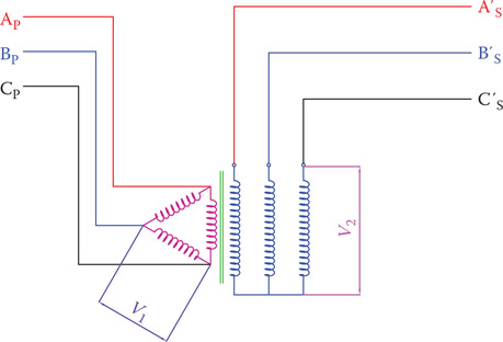
Figure 10.18
The voltage relationship between windings in a three-phase transformer.

Figure 10.19
Symbol for showing three-phase transformer and connection configuration.
In practice, to show the connection configuration of three-phase transformers, a symbol as shown in Figure 10.19 is used. This figure shows that the primary is delta connected and the secondary is wye connected and is grounded at neutral. For three-phase transformers, high voltage terminals are marked by H1, H2, and H3, and the other ones are marked by X1, X2, and X3. H′ and X′ may be used for indicating the other side of each winding.
When connecting three-phase transformers or when connecting three single-phase transformers to form a three-phase transformer, special care must be taken in the correct order of connecting the 12 available terminals. Any connection made in the wrong order can lead to damaging the transformer and other equipment. An identification of various terminals and a sketch of how they must be connected, based on the required configuration is of paramount importance.
Example 10.4
The turns ratio in a step-up transformer is 1:2.65. The primary line voltage is 4160 V and the primary windings are connected in Δ. Determine the secondary line voltage (1) if the secondary windings are also connected in Δ and (2) if the secondary windings are connected in Y.
- Because the primary and secondary windings have the same type of connection, the secondary line voltage is multiplied by the turns ratio:
Secondary line voltage = (4160)(2.65) = 11,024 V
- Voltage between the two ends of each secondary winding is 2.65 times of that of the primary, i.e., 11,024 V. Line voltage is the voltage between each two of phase lines, which is times larger (see Chapter 9). Thus, the line voltage for this configuration is
(11,024)(1.73) = 19,071 V
Example 10.5
The primary winding of a transformer is Y connected to 11,000 V line. If the secondary winding is Δ connected, and the turns ratio in the transformer is 15:1, what is the secondary line voltage?
Solution
Because the primary is Y connected, the voltage affecting each winding is times smaller. This smaller voltage is transformed and reduced by the turns ratio.
6350.85 ÷ 15 = 423.4 V
Thus, the secondary line voltage is 423.4 V.
Example 10.6
A three-phase load takes 25 A from the secondary of a step-down transformer supplying 418 V line voltage. If the transformer secondary windings are delta connected and its primary windings are Y connected, find the current in the primary of this transformer. The transformer turns ratio is 20:1.
Solution
The nominal apparent power for the load is .
Because the secondary is delta connected and the primary is Y connected, the line voltage in the primary is
Because for three-phase circuits apparent power = , the current in the primary circuit due to this load is
Example 10.7
A three-phase delta-delta transformer is used to convert 14,400 to 380 V. Find the turns ratio.
Solution
Because nothing is mentioned about the two given voltages, they are the line voltages of the primary and secondary sides. Because both windings are delta connected, the ratio between the line voltages can directly determine the required turns ratio.
Turns ratio = a = 14,400 ÷ 380 = 37.9.
10.8 Transformer Applications and Power Rating
A transformer is usually designed for a specific purpose with a specific power capacity and a frequency range. This determines many mechanical and electrical parameters involved, such as core dimensions, number of turns, current, and wire size, as well as the type and amount of cooling, if necessary.
For all electrical transmission and for stepping down the voltage for all domestic and industrial devices the frequency is either 50 or 60 Hz, but transformers are also used for audio and video signals and for radio frequency (RF) applications. Audio transformers work at audio frequencies (50–20,000 Hz) and transformers for RF work at much higher frequencies. As the frequency increases, the size decreases. Also, the number of turns in each winding decreases. For this reason, the transformers for high-frequency signals are much smaller than those for 50 and 60 Hz. Most of transformers of this type are single-phase transformers and work at very small power, even at a fraction of 1 W (any necessary amplification of signals is performed after all the processing). Figure 10.20 illustrates two of these transformers in an electronic circuit.
On the other side of the spectrum, transformers for transmission and distribution of electricity may carry millions of watts of power. These transformers, normally three phase, need cooling for taking away the heat that is generated in their windings and core. An example of such a transformer is depicted in Figure 10.21. A large transformer that need cooling can be air cooled or oil cooled. Oil-cooled transformers are inside an oilfilled container. The oil circulates and removes the heat generated in the transformer. They might need a radiator and other components such as a pump, a fan, and an automatic system to start and stop these devices when necessary, based on the temperature.
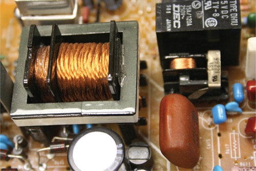
Figure 10.20
Very small and low-power transformers in electronic circuits.
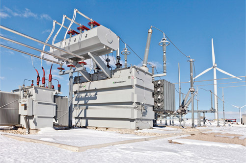
Figure 10.21
A wind farm transformer. (Courtesy of SPX Transformer Solutions, Inc. All rights reserved.)
While small transformers are rated in watts, like 500 W, the large industrial transformers are rated in volt-amperes (VA) (e.g., see Figures 10.8 and 10.21). Rating represents the maximum capacity of a transformer.
Like most machinery a transformer has the highest efficiency (see Section 10.9) if it is used at the rating it is designed for. Although it is possible to use a higher rated transformer at lower powers, the core losses makes it less efficient at lower powers.
10.9 Transformer Efficiency
Efficiency of any device or a system is the ratio of the output power to the input power. That is, the ratio of the power taken from the system to the power given to the system (or consumed by the system). On the basis of the definition, for an ideal transformer, the secondary power is the same as the primary power. That is, the output and input powers are equal. This implies an efficiency of 100 percent. The ideal transformer is for the purpose of determining the minimum voltage and current.
For a real transformer the efficiency cannot be 100 percent. Transformers, in general, have good efficiency. For well-designed large transformers it can reach up to 98 percent. For such a transformer in service for 24 hours per day even that 2 percent shortage from 100 percent can translate to a sizable amount of money in the long run. For this reason, whenever necessary, the efficiency of a transformer must be determined.
Two main categories of power loss in transformers are core loss and copper loss (see Section 10.4). These two represent the energy that turns into heat, for which a transformer must be cooled. The main reason for core loss is eddy current as described in Section 10.4. In addition to eddy current the losses are due to hysteresis and leakage of magnetic energy. These all depend on the design, material, and construction quality of a transformer. Hysteresis loss is due to the nature of alternating current magnetizing effect on ferromagnetic metals. Each time the magnetic field is reversed, there is a chance for losing a small amount of energy. Leakage implies a tiny amount of magnetism lost or leaked out while flowing through the core. Core loss is almost independent of load, but copper loss depends on the current, thus it is load dependent. Input power to a transformer is equal to the output taken from it plus these two losses. In this sense, the efficiency of a transformer can be defined as
| (10.3) |
where the second term in the denominator represents the copper loss. It is written this way to indicate that it is load dependent. When the load on the secondary increases, the current goes up, and this loss goes up, too.
Hysteresis: Property of keeping an effect after its cause has ceased. This is particularly noticeable in electromagnets and electric machines that maintain the effect of magnetization.
Leakage (in transformer): Part of the (magnetic) flux produced by the primary winding that is lost and does not reach (link) the secondary of a transformer, due to structural imperfection.
If the information about the core loss and the copper loss is known, the efficiency of a transformer can be found for each load. Note that both the primary and secondary windings contribute to the copper loss. In practice, the efficiency of a transformer for a given period can be found from a more practical equation as follows. The value found this way represents the energy efficiency of a transformer.
Energy efficiency: Overall efficiency of a transformer in a period of time, for example, in one year; That is, the ratio of the energy provided by a transformer in a length of time divided by the energy consumed by the transformer in the same period.
| (10.4) |
This equation deals with the measurement of the consumed energy by the transformer and the energy supplied to the transformer loads, instead of dealing with power components that might be difficult to measure. Usually, a period of 24 hours is used, and the term all-day efficiency is employed:
| (10.5) |
All-day efficiency: Average efficiency of a transformer during a 24-hour period.
Note that even if the efficiency of a transformer is very good at full load, if it works at a fraction of its load, efficiency drops to a lower level. This is a problem that can be observed particularly in wind turbines because a wind turbine does not have the same rate of generation at all times. Its power generation depends on the available wind and its speed. In selecting a transformer for a wind turbine this fact must be taken into consideration.
Example 10.8
When a 8.5 kW load with a power factor of 0.82 is connected to a 10:1, 14.1 kVA single-phase transformer, the secondary current is 250 A. and the transformer efficiency is 94 percent.
(1) What is the current in the primary? (2) What are the losses in the transformer? and (3) What is the primary voltage?
Solution
- Because the current in the secondary is known, the current in the primary can be found from the turns ratio and the efficiency.
-
Assuming the transformer has the same power factor as the load, the active power supplied by the transformer is
The transformer loss, therefore, is
9043 − 8500 = 543 W
- The apparent power taken by the transformer is
and based on the primary current the applied voltage is
Example 10.9
In the transformer of Example 10.8, the core loss is 300 W. What is the copper loss at full load under the same conditions, if the transformer efficiency at full load is also 94 percent?
The deliverable active power at full load is
Power × Efficiency × pf = (14,100)(0.94)(0.82) = 10,868 W
and the power loss is
(14,100)(1 − 0.94)(0.82) = 694 W
Because the core loss is independent of load, it remains at the same value as before. The copper loss, therefore, is
694 − 300 = 394 W
Another way to look at this problem is to observe that in the previous problem the output power of the transformer was 11,027 VA, which translates to
That is, the transformer was at 78.2 percent load, having a primary current of 25.6 A. At full load, thus, the primary current is
and because the copper loss is proportional to the square of current, thus,
Copper loss = (543 − 300)(1.28)2 = 398 W
Example 10.10
Average power taken from a transformer is 25 kW, 10 hours per day. The energy consumption in 24 hr according to a meter is 280 kWhr. What is the all-day efficiency of this transformer?
Example 10.11
The efficiency of a 750 kVA transformer is 98 percent. If the average duty cycle of this transformer when in service for 24 hrs, 7 days per week is 85 percent, find the amount of energy turned to heat each year, in term of BTU and calories. If each kilowatt-hour of energy costs $0.08, determine how much is the cost of the energy lost this way (1 joule = 0.2388 cal; 1 joule = 1 watt-sec; 1 watt = 3.412 BTU/hr).
Solution
We first calculate the amount of electrical energy lost per year in kilowatt-hour.
Energy lost per year = (750)(1 − 0.98)(0.85)(365)(24) = 11,690 kW-hr
Cost of lost energy = (11,690)(0.08) = $935.2
1 watt = 3.412 BTU/hr → 1 watt-hr = 3.412 BTU
11,690 kW-hr = (11,690,000)(3.412) = 39,886,280 BTU
11,690 kW-hr = (11,690,000)(3600) = 42,084,000,000 J = 42,084,000 kJ
42,084,000 kJ = (42,084,000)(0.2388) = 10,049,659 kcal
Another measure for performance of a transformer is its voltage regulation. Voltage regulation reflects how large or small is the change of voltage (due to voltage drop inside a transformer) when the load on a transformer changes, say from full load to 80 percent. Voltage regulation is expressed in percent and is determined from
| (10.6) |
Voltage regulation: Percent value representing how good a transformer is, obtained from the ratio of voltage loss to the transformer nominal voltage. The smaller this number is, the better the transformer.
The smaller the voltage regulation, the better the transformer because it implies that there is smaller copper loss in the transformer. For an ideal transformer the voltage regulation is 0 percent because it has no loss and no voltage drop.
Example 10.12
A transformer is used to change 4160 to 120 V. If the voltage across a load is 116 V at full load, what is the voltage regulation of this transformer?
Solution
The turns ratio of the transformer is
Thus, the primary voltage at full load is
(116)(34.67) = 4022 V
and the voltage regulation is
10.10 Transformer Circuits
Loads of any type (resistive, inductive, and capacitive) can be connected to the secondary of a transformer. Thus, in general, the secondary of a transformer has a current that, depending on the values of R, L, and C, has a phase difference with its voltage. Depending on this current, primary current and its phase difference with the primary voltage can be determined. In what follows we discuss the way this is done, which is much more complicated than the relationship for the ideal transformer. The analysis is always done for a single-phase branch but can be extended with the rules in Chapter 9 for three-phase loads, even if not balanced.
10.10.1 Transformer Model
A simplified electrical model of a single-phase transformer or one phase of a three-phase transformer is shown in Figure 10.22. Primary winding has a resistance R1. Also, in addition to the main winding inductance, an inductance L1, which at the working frequency exhibits a reactance X1 is added for the magnetic leakage of primary winding. Similarly, secondary winding has a resistance R2 and an inductance L2, the reactance of which at the working frequency is X2. Core losses can be shown in the form of a resistance in a parallel branch with the winding. So, load change does not affect the current through this branch.
If a voltage V1 is applied at the terminals of the primary winding, a current I1 flows in the primary winding. This current consists of Ic, a current assumed for the core loss, called the core loss current, and Im, the magnetizing current. Owing to the voltage drop in the winding the voltage magnetizing the core is E1, which is smaller than V1. Because of the mutual inductance between the windings, an AC voltage is available across the terminals of the secondary winding. With the secondary being open, this voltage is equal to E2, which is found from the voltage relationships (Equation 10.1) for the ideal transformer. But, if a load is connected to the secondary winding this voltage reduces to V2 (V2 < E2) because of voltage drop in the secondary winding (R2 and X2).
Core loss current: Current in the primary winding of a transformer that corresponds to the core losses; that is, it is equal to the core loss power divided by the primary voltage. It exists even if there is no load connected to a transformer.
Magnetizing current: Part of the current in a wire winding that corresponds to creating a magnetic field.
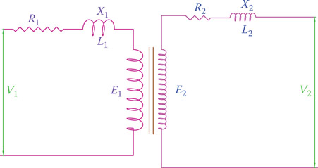
Figure 10.22
Trans former electrical model.
The current I2 in the secondary is V2 ÷ Z2, where Z2 is the load impedance. Before we can continue with the corresponding relationships for this model and see how to find the current in the transformer primary due to a load, we need to associate the secondary parameters to the primary, as discussed in Section 10.10.2.
10.10.2 Primary-Secondary Load Interchange
It is customary for transformers to refer the loads in the secondary, to the primary. This implies replacing the secondary loads by their equivalent values, as if they were connected in series with the primary winding instead of the transformer. Writing
and substituting for V2 and I2 from Equations 10.1 and 10.2 in terms of V1 and I1 leads to
This relationship implies that the equivalent of Z2 if substituted in the primary circuit is a value proportional to the square of the turns ratio. If the value is denoted by , then
| (10.7) |
is said to be the secondary load as seen from the primary. This equation is general and is also valid for resistance, capacitance, and inductance, as well as the winding parameters (R2 and X2 in Figure 10.22). Moreover, the inverse of the same thing is valid if a value must be referred to the secondary from the primary circuit.
Example 10.13
If the turns ratio in a transformer is 10, what is the resistance as seen by the primary of a 5 Ω load that is connected to the secondary, assuming an ideal transformer?
Example 10.14
A three-phase transformer changes 14,270 to 240 V. A 24 kW heating load is connected to each secondary. What is the resistance of this load as seen by the primary? Assume an ideal transformer.
The turns ratio for this transformer is
Resistance of the load is
Note that the secondary current is .
On the basis of the current relationships the primary current for this load is .
And if the primary current is calculated from the primary voltage and its assumed load of 8600 Ω resistor, it is . The slight difference observed here is because of the round-off errors (a is not exactly 60).
On the basis of the aforementioned discussion, Figure 10.23 depicts the electrical model of a transformer when the effects of the secondary winding resistance and leakage reactance are referred to the primary. We see that when the secondary is open there is no current in the secondary (I2 is zero), but Ic and Im still exist. Also, there is no voltage drop due to and . The only voltage drop in V1 is due to and X1 and the currents Ic and Im.
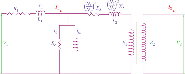
Figure 10.23
Transformer equivalent circuit when the secondary parameters are referred to the primary.
When there is no load, the current in the primary winding is denoted by
| (10.8) |
This is the current that is ignored in an ideal transformer. When the secondary of a transformer is open, the transformer behaves like an inductor.
10.10.3 Measurement of Copper Loss and Core Loss
Core loss and copper loss at rated current are experimentally found for a transformer by two well-accepted standard tests. These are called open-circuit test and short-circuit test.
Open-circuit test: Test for measuring current in the primary of a transformer when the secondary winding is not connected to any load. This measurement determines the core loss (the losses for magnetization, leaks, and eddy current, which are load independent) of a transformer.
Short-circuit test: One of the two important tests for transformers. Short-circuit test measures the copper losses of a transformer. The secondary winding is shorted for this test.
In the open-circuit test the secondary of a transformer is open, and there is little current in the primary (therefore, the copper loss is very little). To a good approximation, the reading of a wattmeter that measures the consumed power represents the core loss (the copper loss in this test is negligible).
The short-circuit test measures the copper loss. For this test the secondary winding is short circuited and a low voltage is applied to the primary terminals. This voltage is much smaller than the rated voltage; it is experimentally adjusted such that the primary winding current reaches its maximum rated value. (If this test is done with the rated voltage, the transformer immediately overheats and gets damaged.) With a good approximation the wattmeter reading in this test represents the copper loss because this current is much more than that in the open-circuit test. Hence, a small part of this current corresponding to core loss (which still exists) can be ignored.
For a transformer, the open-circuit test determines the core loss and the short-circuit test determines the copper loss.
In the short-circuit test, the voltage that causes the rated current in the transformer primary has a specific significance. The percent ratio of this voltage to the rated voltage is called transformer percent impedance (denote by Z%). This number defines two things:
- How much voltage drop in the primary exists under full rated current
- How much the maximum secondary current is that a transformer can handle if a short circuit occurs in the secondary.
Transformer percent impedance: Percent ratio of the voltage in the short-circuit test of a transformer that causes the rated current to the rated voltage.
Item 2 is based on what secondary current causes 100 percent voltage drop in the primary winding. For industrial transformers smaller than 1 MVA the value for percentage impedance is around 5 percent, but as the power and the voltage rating increase this value increases up to 22 percent. The smaller this value is the better the transformer is. The following example shows a practical application of the percentage impedance.
Percentage impedance of a single-phase 15 kV to 415 V transformer is 5 percent. If its rated power is 30 kVA, find (1) what the voltage drop in the primary is and (2) what the maximum short circuit current for the secondary is.
Solution
- Maximum voltage drop in the primary at the rated voltage is
(15,000)(0.05) = 450 V
- Full load current in the secondary is
and the maximum short circuit current is
The information from the latter part can be used for selection of breakers and fault protection devices.
10.11 Chapter Summary
- All transformers work based on mutual induction between two windings.
- Windings must have a common core; core is made out of laminated ferromagnetic metal.
- A transformer can increase or decrease voltage.
- A step-up transformer increases voltage, and a step-down transformer decreases voltage.
- The input side of a transformer is called primary, and output side is called secondary.
- The key issue in a transformer is that the primary side power is equal to the secondary side power and the power losses.
- Power losses are categorized to core loss (due to eddy current, hysteresis, etc.) and copper loss (due to current flow in the wire windings).
- In an ideal transformer the losses are ignored. Primary power is equal to the secondary power.
- Rated values of a transformer are for the operating voltage and frequency, and maximum power that a transformer is designed for.
- A three-phase transformer can have a single core or it can be made up of a bank of three identical transformers.
- In a three-phase transformer the primary and secondary can be independently connected with star or delta configuration.
- There are four different configurations for connecting three-phase transformers, delta-delta, delta star, star-delta, and star-star.
- In delta-star and star-delta connections, there is a 30° phase difference between the primary circuit and the secondary circuit.
- Attention to polarity and primary/secondary sides is very important in making connections in transformers.
- There are two important tests for measuring transformer parameters, open-circuit test and short-circuit test. The former measures the core loss, and the latter measures the copper loss.
- The efficiency of a transformer is the ratio of output power from the secondary to the input power the primary takes from mains.
- All-day efficiency of a transformer is based on its output and input in a period of 24 hours.
- Transformer percent impedance can be used to see how much voltage drop occurs in the primary at full load. It also serves for a measure of the maximum current in a shorted secondary.
Review Questions
- What is the main purpose of a transformer?
- What is the basic construction of a transformer?
- What are primary and secondary windings?
- Is the primary voltage larger or smaller than the secondary voltage?
- What does increase in a step-up transformer?
- Define an ideal transformer.
- Define an isolation transformer.
- Is it possible in a step-down transformer to have a lower current in the secondary? Why or why not?
- What is turns ratio?
- Define volt per turn.
- Is the volt per turn larger in the primary or in the secondary?
- What are the two categories of main losses in a transformer?
- If frequency changes, does it affect the performance of a transformer? Explain.
- In a real transformer, where does the difference between the primary and secondary powers go?
- Is the current larger in a transformer when it has a load or when it does not have a load?
- What is the efficiency of a transformer?
- What is a typical acceptable figure for the efficiency of a transformer?
- What is the energy efficiency?
- What is all-day efficiency?
- What is the voltage regulation of a transformer?
- Why is the core in a transformer laminated?
- What is copper loss?
- What are the two tests for a transformer? What are determined by these tests?
- Can one use three single-phase transformers in place of a three-phase transformer?
- What are the four configurations that a three-phase transformer can be connected?
- Is there any phase difference between the primary and secondary voltages in a single-phase transformer?
- Is there any phase difference between the primary and secondary voltages in a three-phase transformer?
Problems
- The primary winding of a 10:1 single-phase transformer has 500 turns. Assuming an ideal transformer, what is the number of turns of the secondary?
- If the transformer in Problem 1 provides 415 V, what is the primary voltage?
- If the rated power of the transformer in Problem 1 is 15 kVA, what is the maximum secondary current?
- A 500 W resistive load is connected to the secondary of a step-down transformer. Primary and secondary voltages are 220 and 110 V. What are the currents due to this load in the secondary and primary windings, assuming an ideal transformer?
- The turns ratio in a step-up transformer is 8.4. The primary line voltage is 4160 V, and the primary windings are star connected. Determine the secondary line voltage (1) if the secondary windings are also star connected and (2) if the secondary windings are delta connected.
- The primary winding of a transformer is Y connected to a 4100 V generator. If the secondary winding is Δ connected and the turns ratio in the transformer is 14.6:1, how much is the secondary line voltage?
- A three-phase load is connected to a 208/120 V line by a delta configuration. The line is fed from a 600 V Y/Δ transformer. Find the current in the primary of this transformer if the load current is 75 A.
- A single-phase transformer is part of a bank to transform 125 to 21 kV. If a Δ/Y configuration is employed, determine the line to neutral voltage in the secondary and the turns ratio of the transformer.
- A three-phase delta-star transformer is used to convert 11,400 to 480 V. Find the turns ratio.
- A load with a power factor of 0.85 is connected to the secondary of a 12,000/480 V, 48 kVA single-phase transformer. Secondary current is 62.50 A, and the transformer efficiency is 95 percent. (1) What is the current in the primary? and (2) What are the total losses in the transformer?
- In the transformer of Problem 10, the core loss is 500 W. What is the copper loss at full load under the same conditions if the transformer efficiency at full load is also 95 percent?
- During a 24-hour period the average power taken from a transformer is 30 kW. The corresponding energy consumption in 24 hr is 840 kW-hr. What is the all-day efficiency of this transformer?
- A three-phase transformer rated at 75 kVA is used to feed a plant. The plant contains a number of motors, lighting, and auxiliary devices that altogether consume 70 kW energy. The bill paid at the end of a 30 day month for this plant is $5760. If the cost of electricity is $0.08 per kW-hr, what is the energy efficiency of this transformer?
- A three-phase transformer is used to step down 4160 to 208 V. If the line to line voltage measured is 200 V at full load, what is the voltage regulation of this transformer?
- Turns ratio in a three-phase transformer is 26:1. A 25 Ω load is connected to the secondary. What is the resistance of this load as seen by the primary?
- A transformer is used for stepping up 7200 to 34,400 V. What is the impedance as seen by the primary for a 240 mH inductor connected to the secondary?
- A transformer changes 660 to 240 V. If a 3 kW load is connected to the secondary, assuming an ideal transformer, what is the resistance of this load as seen by the primary?
- The percentage impedance of each phase of a three-phase 480 to 120 V transformer is 5 percent. The transformer rated power is 4 kVA. (1) What is the voltage drop in the primary? and (2) What is the maximum short circuit current that the secondary protection circuit should handle?
- Core loss and copper loss for a transformer have been determined to be 200 and 1700 W at full load. The full load secondary current is120 A. What is the total loss of this transformer at 80 percent load?
- A 26:1 three-phase transformer is rated 45 kVA. If the primary voltage is 12,680 V, what is the voltage drop in the primary if the secondary voltage is 473 V? What is the rated primary current for this transformer?
- A three-phase transformer with the turns ratio 5:1 is used to power a plant. The supply line voltage is 2400 V. If the secondary circuit allows a maximum current of 20 A, find what the maximum power that can be drawn is for each of the following cases of the transformer connection: (1) delta-delta, (2) delta-wye, (3) wye-delta, and (4) wye-wye.
Advanced Learning: Real Transformer Circuit Analysis
The phase difference between the voltage and current in the secondary and primary circuits of a transformer makes it rather difficult to analyze loads and determine power loss and voltage drop. In this section a simplified version for tackling transformer circuits is discussed. A few examples are included for illustrating the matter.
We refer to Figure 10.22 and the discussion in Section 10.10.1. We learned that if an AC voltage V1 is applied to the primary winding, an AC voltage is available across the terminals of the secondary winding. If there is no load on the transformer, secondary current I2 is equal to zero and this voltage is equal to .
The following two equations constitute the relationships for a transformer:
| (A10.1) |
| (A10.2) |
ZI1 represents the total voltage drop due to the load and the core and magnetizing losses. The variables in Equations A10.1 and A10.2 are not in phase with each other; thus, the values must be added in the vector form (see Figure A10.1a).

Figure A10.1
Phase relationships between I1, I2, V1, and V2 in a simplified real transformer. (a) Real situation: I1 and I2 are not in phase; V2 and E1 are not in phase. (b) Simplified form: I1 and I2 are assumed in phase; V2 and E1 are assumed in phase.
When a load is added to the transformer (secondary), secondary current I2 is not zero anymore, and the secondary terminal voltage is no longer E2;
I2 and V2 depend on the type of load (inductive, resistive, capacitive) and the losses, which depend on the parameters of the transformer.
When the secondary has a current in it, the effects of R2 and L2 must also be brought into consideration. (They contribute to the voltage drop in the primary, which results in a decrease in V1, E2, and V2.) The effect of the transformer parameter can be represented by Z0 and the load impedance is denoted by Z2. Z0 is the total impedance due to the resistance and inductance of both primary and secondary windings (see Figure 10.23 and Equation 10.7). (Note that the R and X terms are added in the vector form. A bar on the letter denotes this.)
| (A10.3) |
The total load Z1 on the primary is (when the transformer load is referred to the primary)
| (A10.4) |
and the secondary and primary currents can be found, respectively, from
when V1 and V2 are known.
Example A10.1
Data for a 3:1 step-down three-phase transformer are R1 = 2.3 Ω, R2 = 0.07 Ω, X1 = 8.47 Ω, and X2 = 0.304 Ω per phase. If the three-phase balanced load on the secondary can be represented by a 42 Ω resistor (Z2 = 42) per phase, find the total impedance of the primary.
Solution
For this transformer, all calculation is done for one phase because the load is balanced.
R0 = R1 + R2 = 2.3 + (3)2(0.07) = 2.93 Ω
X0 = X1 + X2 = 8.47 + (3)2(0.304) = 10.206 Ω
In this example the load is purely resistive because it is represented by a resistor. Together with R0 the total resistive value of the load is 2.93 + 378 = 380.93 Ω. The reactance values are at 90° lagging. Thus, the total impedance of the primary is
Example A10.2
In Example A10.1 if the full load current in the primary is 89 A,
- What is the applied primary voltage?
- What is the voltage drop in the primary at full load?
- What is the no load primary current?
- What is the power rating of this transformer?
Solution
- V1 = (381.067)(89) = 33,915 V
-
- For this question with good approximation we may say that the ratio between the no load current to the full load current is the same ratio for the impedance values in 1 and 2. Thus,
- Primary voltage of this transformer is 33,915 V (nominally 33,000 V), and its full rate current is 89 A. Its power rating, therefore, is
In a real transformer a thorough analysis of the relationships between V2 and E1 is cumbersome, because of the phase differences as shown in Figure A10.1a and the core losses that are current independent. Here we use a simplified version based on certain assumptions that, to a great degree, are acceptable. The assumptions are as follows:
- Primary and secondary currents are in phase with each other.
- Voltages E1 and V2 are in phase with each other.
- Core losses are ignored, because they are relatively small.
On the basis of these assumptions, the phase relationships between various transformer variables become simpler, as can be seen comparing Figure A10.1a and b. In this figure, ZI1 is the effect of copper losses that is subtracted from V1 to find E1. The third assumption allows replacing Z by Z0 in the figure.
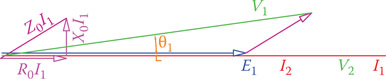
Figure A10.2Phase relationships between I1, I2, V1, and V2 when θ2 = 0.
Note that even if θ2 = 0, θ1 is not zero. When the load is purely resistive, or in the case of no load, θ2 = 0 and I1 coincides with E1 (as well as I2 coinciding with V2). Figure A10.2 illustrates a case when θ2 = 0.
In Figure A10.1b the terms R0I1, X0I1, and Z0I1 are exaggerated. In reality, as can be observed from Example A10.2, the value for Z0I1 is much smaller than V1. In this respect, the difference between angles θ1 and θ2 is very small, particularly when θ2 is nonzero. This allows us to approximate the relationship in Equation A10.1 to arithmetic sum instead of vector sum (see Figure A10.2).
Example A10.3
In a three-phase 33,000 V/11,000 V transformer a load takes 150 A from the secondary. If, the primary voltage is 33,200 V, determine (1) What the voltage V2 is, (2) How much power the load takes, and (3) What the efficiency of the transformer is. Assume the same values of resistance and reactance as in Example A10.1 for the transformer.
Solution
-
Preliminary steps for calculation of R0 and X0 are the same as in Example A10.1 and are repeated here for convenience.
R0 = R1 + R2 = 2.3 + (3)2(0.07) = 2.93 Ω
X0 = X1 + X2 = 8.47 + (3)2(0.304) = 10.206 Ω
Because this is a step-down transformer, current in the primary winding is smaller than I2:
-
Voltage drop in the primary winding is
ΔV = (10.618)(50) = 531 V
The secondary voltage, therefore, is
and the power taken by the load is
- Efficiency is the ratio of the output power over the input power