
16
Diode Rectifiers and Filters
OBJECTIVES: After studying this chapter, you will be able to
- Describe how AC is converted to DC
- Explain the quality of direct current as obtained from a rectifier
- Define ripple and how one can reduce ripples
- Understand the significance of filtering in rectified electricity
- Describe how one can add filters to a rectified waveform
- Explain what a half-wave rectifier and a full-wave rectifier are
- Define bridge rectifier
- Make a diode rectifier for single-phase AC
- Make a diode rectifier for three-phase AC
- Construct a power supply with filtered and regulated output
- Define various types of filters
- Define and use low pass filters, band pass filters, high pass filters, and band reject filters
New terms: Attenuation, band pass filter, band reject filter, band stop filter, bandwidth, bridge rectifier, full-wave rectifier, half-wave rectifier, high pass filter, low pass filter, ripple, ripple factor, surge, surge suppressor, tank circuit
16.1 Introduction
A rectifier is a device to convert AC electricity to DC. Except batteries that are small sources of DC electricity, or the rechargeable ones that store electricity, most of the domestic devices that work with DC electricity use rectifiers. At the industrial level, there are industries that need DC electricity to run DC motors or processes that can function only with DC; they either must have their own generators or must obtain their DC requirement from AC sources by rectifiers.
Both single-phase and three-phase AC can be converted to DC. For domestic products and small applications, single-phase rectifiers suffice, but for large loads at the industry level, such as electroplating, electrolytic metal refining and high voltage direct current (HVDC) transmission and smaller ones like DC motor drives, three-phase converters are employed. Converter is a term that is used for both rectifier and inverter (inverter does the opposite job of providing AC from DC; discussed in Chapter 20).
In the simplest form a rectifier consists of a number of diodes, and therefore, we can call it a diode rectifier. And, as you can guess, there are other type(s), as will be discussed in Chapter 20. Diode rectifiers are simpler than the other types that use switching devices. Hereafter in this chapter the word diode is omitted for simplicity because the discussion implies that only diode rectifiers are concerned. The most common and widely used single-phase rectifier is the bridge rectifier, but full-wave rectifiers and half-wave rectifiers can also be used.
Bridge rectifier: Full-wave rectifier of AC using four diodes (for single phase) or six diodes (for three phase) to obtain direct current from alternating current.
Full-wave rectifier: Rectifier in which both half cycles of an alternating current waveform are rectified and delivered to the output as DC, as opposed to a half-wave rectifier in which only one half of each cycle reaches the output.
Half-wave rectifier: Simplest type of rectifier for alternating current, consisting of only one diode (for single phase) and three diodes (for three phase) that block the negative half cycle of AC, so that only the positive half cycles are passing to the output.
16.2 Half-Wave Rectifier
Figure 16.1 shows the schematic of a half-wave rectifier, which is the simplest and lowest quality type of rectifier. But, it demonstrates the principle of how rectifiers work. It consists of only one diode inserted in an AC circuit. As a result, for each full cycle of the alternating current the diode conducts only for half of the cycle but blocks the current for the other half. The outcome is shown in Figure 16.1c, which is a DC voltage as seen by a load.
The performance of a half-wave rectifier is very poor, and the DC voltage has a lot of fluctuation. The DC voltage here is, in fact, a series of half sinusoidal pulses (a pulse is a short duration DC signal). This variation of the voltage level, called a ripple, can be smoothed out to some extent by employing a filter. Note that the variation of voltage reflects in a load, depending on what the load consists of. Unless otherwise said, the load for this rectifier is everything that is connected in the circuit and is represented by R in Figure 16.1. All that we have learned about series and parallel components comes into view. An average value for the DC voltage, which lies somewhere between zero and maximum (peak values of the AC voltage), can be determined.
Ripple: Fluctuations in a rectified AC waveform. Fast fluctuations in an electrical value, such as voltage, that is supposed to be constant.
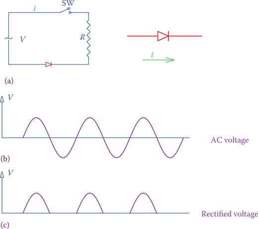
Figure 16.1
Half-wave rectifier. (a) AC circuit. (b) AC voltage across resistor without the diode. (c) Voltage across resistor when diode is added to the circuit.

Figure 16.2
Schematic of a half-wave rectifier and the effect of a filter on the load voltage.
The most common filter is one or more capacitors connected across the positive and negative poles of the DC voltage, that is, in parallel with the load. Half-wave rectifiers are used only in applications for which a crude DC voltage is acceptable, like battery charging. A half-wave rectifier with filter and its output to the load (filtered output) are shown in Figure 16.2. As can be seen, as a result of the capacitor (filter), output voltage is not as before, meaning that the voltage does not vary between zero and the peak value of the alternating current. It varies between a minimum and a maximum. Variation of the voltage in the filtered output is between the peak value and a nonzero positive magnitude. The average DC value in this case is larger than in the unfiltered case. The larger the capacitor, the larger is the minimum value and the difference between the minimum and the maximum (the ripple) is smaller. The average DC value, as a result, is higher.
In a half-wave rectifier the ripple amplitude is rather high. The ripple frequency is the same as the frequency of the input AC signal.
To convert DC to AC a half-wave rectifier eliminates the negative half in each cycle of AC.
16.3 Full-Wave Rectifier
The half-wave rectifier uses only a half cycle of an AC waveform. A full-wave rectifier has two diodes, and its output uses both halves of the AC signal. During the period that one diode blocks the current flow the other diode conducts and allows the current. The schematic of a full-wave rectifier is shown in Figure 16.3, where the unfiltered output voltage is also illustrated. The AC source is shown as a transformer. This is the reality in many rectifiers. First, the voltage is lowered (or increased) to a desired value, and then it is sent to the rectifier.

Figure 16.3
Schematics of a full-wave rectifier.
As can also be observed from Figure 16.3, the two similar sides of the diodes are connected together and are connected to one side of the load. The other side (of the load) is connected to the center point of the transformer secondary winding. This implies that the transformer must have a center tap and it is required that access to this point is available. Furthermore, in a full-wave rectifier the DC voltage obtained corresponds to only half of the supplied voltage. Thus, for a direct conversion of the mains supply of 120 V to DC one needs a 1:2 transformer with a center tap. This is one of the drawbacks of a full-wave rectifier.
The average value of the unfiltered DC voltage obtained this way is only 45 percent of the effective voltage of the transformer secondary. In this sense, if the effective (rms) voltage in the transformer secondary of Figure 16.3 is 240 V, for instance, the average value of the rectified (DC) voltage is
DCAV = (0.45)(VEff) = (0.45)(240) = 108 V
Practically, this average value is not so useful except in simple and cheap battery chargers. This is because in most cases, in practice, a capacitor (or other filter; see Section 16.8) is used to reduce ripples. The effect of a filter added to a circuit (the simplest is a capacitor in parallel with the rectifier load) is shown later.
The average DC value of the output of a full-wave rectifier is twice as much as a comparable (having the same rectified pulse peak value) half-wave rectifier because it has twice as many pulses. The frequency of its ripples is also twice. The filtered output has much less ripple content than that of the half-wave rectifier. The frequency of ripples is 2 times the frequency of the mains.
Ripple is the rapid fluctuations in the voltage of DC electricity obtained from rectified AC.
16.4 Bridge Rectifier
A bridge rectifier is similar to having two full-wave rectifiers together to obtain the full voltage of the source in the output instead of half. In addition to the voltage relationship, another advantage is, thus, no need for a center tap point. It uses four diodes as shown in Figure 16.4. Pay attention to the way the four diodes are connected together and to the circuit. At each half cycle, two of the diodes conduct and two of them block the current. The resulting rectified waveform, as seen by a load, is similar to those shown for full-wave rectifier, with the exception that the voltage this time is double of that with a full-wave rectifier, all conditions being the same. Figure 16.4 shows the direction of current for one half cycle. Note that we have used the common way for showing electronic circuits; thus, the current path is completed through the ground.
The current through a load connected to a full-wave rectifier or a bridge rectifier flows in one direction only, as if all negative half cycles of the alternative current are converted to positive.
If you trace the flow of current, you will observe that no matter which side of the transformer is at a higher voltage the current through the load is always in one direction. That is, it is direct current. Normally, a capacitor is used to filter the ripples. Always for all rectifiers the higher the capacitance of this capacitor, the better is the filtering effect. The average voltage of the unfiltered DC voltage can be determined from
| VAV=2Vpeakπ=2√2VEffπ=0.90 Vrms | (16.1) |

Figure 16.4
Schematics of a bridge rectifier.
Thus, for a 120 V effective AC voltage the average of the unfiltered output DC voltage is 90 percent of 120 V, that is, 108 V. Nevertheless, after inserting a capacitor this voltage can increase. For a pure resistive load the filtered DC voltage after putting a capacitor in parallel with the load is
| VDC=Vpeak(1−12fRC) | (16.2) |
where R is the load resistance, C is the capacitance of the filter, and f is the frequency of the ripples. This equation shows that a larger capacitor, or a larger load, gives a much smoother DC volt; it also indicates that with the same capacitor a better result is obtained if the frequency of the ripples is higher (e.g., comparing single-phase bridge rectifier with three-phase bridge in Section 16.6).
The effect of filters can be better observed from Figures 16.5 and 16.6, which show the comparison of the filtered and the unfiltered voltage for a particular case. These figures correspond to 14 V AC effective voltage (40 V peak-to-peak) shown on an oscilloscope. Reading on the left is the effective value of the ripples and reading on the right is the average DC value. (Note that always some percentage of the voltages is dropped in the diodes.) Figure 16.6 illustrates the same rectified waveform. The ripples voltage has dropped to 0.4 V, whereas the DC voltage is 16.7 V for the same loading condition.
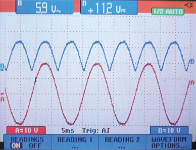
Figure 16.5
Unfiltered output of a bridge rectifier.
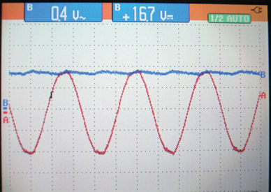
Figure 16.6
Filtered output of the DC output shown in Figure 16.5.
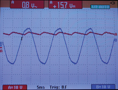
Figure 16.7
Effect of increased load on the DC voltage shown in Figure 16.6.
How much the average DC voltage is and how much ripple remains in the rectified DC depend on the nature of the load, its power consumption (circuit current), and the filter (capacitance of the capacitor), as can be determined from Equation 16.2. Figure 16.7 depicts the effect of increasing the all resistive load (increase in current) for the same case in Figure 16.6.
A bridge rectifier is practically the most common and most frequently used rectifier for single-phase AC. Nowadays it is possible to buy the four diodes integrated together in one package, as shown in Figure 16.8. They come in different shapes. It can be larger than a single diode, but the size depends also on the voltage and current rating (power). It has two input terminals to connect to AC and two output terminals, which provide the DC electricity. Any capacitor for filtering and the load are connected to the DC side.
In practice, the power rating of a rectifier and the maximum voltage are the main consideration for selection of a proper rectifier. As in DC, power is the product of voltage and current. Thus, for a particular application the rectifier diodes must stand the applied voltage and the circuit current.

Figure 16.8
Bridge rectifier integrated circuits.
When diodes are used in a rectifier in each half cycle of the AC signal, they are subject to a negative voltage across them when they are reverse biased. A diode must withstand the peak inverse voltage (see Chapter 14). For a single-phase bridge rectifier this voltage is around 1.57 of the DC voltage.
16.5 Ripple and Filters
Ideally, the output of a rectifier must be a perfect DC and look as smooth as a straight line on an oscilloscope, similar to the output from a battery. This implies no fluctuation in the value of the voltage. Because of the nature of rectification, nevertheless, the unevenness of the rectified sinusoidal waveform is present. The percentage of this ripple with respect to the voltage value, however, can be small or large. And the smaller this percentage is, the better it is. For example, the filtered output of a bridge rectifier in Figure 16.5 has a much smaller ripple than the unfiltered output, but it is not as smooth as DC from a battery. The measure of quality of the DC output of a rectifier can be defined in the terms of the ratio of the variation in the voltage (ripple) to the voltage value. For example, if for 24 V DC the ripple is 1 V, (i.e., the voltage varies between 23.5 and 24.5 V), then we may calculate this ratio to be 1/24, or about 4 percent. Alternatively, one may express this ratio in terms of the peak value of the AC voltage, in case it is more appropriate, like 2 V ripple on 40 V peak.
Recall from Chapter 13 (see Section 13.5.6) that one of the functions of filters is to remove unwanted signals. Here, the ripple is an unwanted part of a DC signal that we want to remove. As said, a capacitor is the most common type of filter for this case. Also, capacitors are relatively cheap. There are, nevertheless, other types of filters, a few of which are discussed here.
As you remember, when a capacitor is inserted in a circuit (see Section 8.6), it charges and discharges, based on the polarity of the voltage at its terminals and the previous charge in the capacitor. In doing so, a capacitor introduces a delay in a voltage to develop or change. It all depends on the capacitance of a capacitor and the frequency of a signal (how fast it wants to change).
In the same way that a capacitor acts as a blocking agent for a change in voltage an inductor was a blocking means for a change in current. In this sense, an inductor can also be used as a filter. In fact, a combination of capacitor plus an inductor and sometimes a resistor construct the few types of filters, as we discuss here.

Figure 16.9
Inductor as a filter for the rectified AC.
Figure 16.9 illustrates the schematic of a bridge rectifier with an inductor as filter. Note that contrary to the capacitor filter that was in parallel with load, an inductor filter is in series with the load. Normally, a capacitor is cheaper than an inductor, and therefore the majority of single-component filters use a capacitor.
Other types of filters consisting of capacitors and inductors are L-type filters, T-type filters, and π-type filters. The reason for these names is the resembling of the branches containing the filter elements to an L, T, or the Greek letter π. Figures 16.10 through 16.12 depict different forms of each category. In these figures the diodes (the rectifier part) are not shown. The two terminals for each filter are connected to the output of the rectifier. Note that in T-type and π-type filters a resistance can be employed instead of an inductor. We see more of this later in Section 16.8.
A filter is sensitive to frequency. It can remove all signals of some ranges of frequencies. It attenuates the input signals having those frequencies.
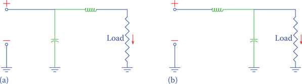
Figure 16.10
L-type filters. The inductor and capacitor form a letter L. (a) Inductor is put after capacitor. (b) Inductor is put before capacitor.
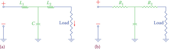
Figure 16.11
T-type filters. The three filter components form a letter T. (a) Two similar inductors are used. (b) Two similar resistors are used.
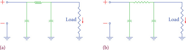
Figure 16.12
The three filter components form the π-type filters. (a) LC filter. (b) RC filter.
16.6 Three-Phase Rectifiers
At the industrial level, where more power is required, a three-phase rectifier is employed. In this way, power is taken from all the three phases, but a single DC supply is obtained. Figure 16.13 depicts the diode arrangement and connections of the most common three-phase rectifier. There are other arrangements, too. To make a distinction among other designs, the design in Figure 16.13 is referred to as a bridge rectifier, full-wave rectifier or full-wave bridge rectifier by different people. For this configuration, connection to the mains is provided by three-phase lines and no provision is available for a neutral line, similar to a delta connection. This arrangement uses six diodes. Other arrangements are also possible, which use only three diodes or 12 diodes, but the three-phase rectifier in Figure 16.13 is more common and more efficient. We do not consider other designs. Similar to all other rectifiers, the output voltage can be filtered for ripple reduction/elimination. Also, as discussed in Section 16.7, the output voltage can be regulated for better quality.
Full-wave bridge rectifier: Same as bridge rectifier.
The average DC voltage from a three-phase rectifier under discussion is approximately 0.95 times the peak value of the line voltage. That is, 0.95 × 2 = 1.35× the nominal (effective) voltage of the supply line voltage. The DC voltage thus is larger than the AC supply peak voltage, as shown in Figure 16.13b. At each instance the voltage difference across the load is determined by the most positive and most negative voltages at the three-phase lines. For example, during the period between 0 and 30° of each cycle, according to the figure shown, the voltage in phase C is the most positive and that in B is the most negative. The load voltage, therefore, is the total voltage difference between the positive value of C and the negative value of B. All of these values are represented by the ver tical lines shown at 10° intervals, for 360° (one cycle) in the figure. These line segments are repeated at the bottom of the figure, showing the DC voltage.

Figure 16.13
Schematics of a three-phase rectifier. (a) Arrangement and direction of diodes. (b) Resulting DC electricity at the rectifier output.
It is easy to see from Figure 16.13 that the frequency of ripples in a three-phase rectifier is 6 times the frequency of the mains supply. Also, compared to the single-phase bridge rectifier, the ripple factor is much smaller. Three-phase rectifiers are revisited in Chapter 20, where more powerful and versatile rectifiers and power converters are studied.
In a DC voltage provided by a three–phase rectifier the ripple frequency is 6 times the supply frequency.
Ripple factor: The ratio of the AC content (peak-to-peak value in volts) of a rectified voltage to its DC content (which is the average value of the rectified voltage). The smaller this ratio is, the better is the rectified value.
In a three-phase rectifier the peak inverse voltage that appears across each diode is equal to the peak of the line (indicated as line-to-line in Figure 16.13, for consistency) voltage. In practice, a safety factor of 2.5 is also considered and for a line voltage v diodes that can withstand 2.5v are used.
16.7 Small DC Power Supplies
Because all electronic devices can only work with DC electricity, almost all of them have a built-in power supply or they have an external power supply that provides DC electricity at the required voltage and power. Examples are plenty, at home and in industry. For instance, radio, television, cellular phone, computer, electronic guitar, and so on, all are powered by AC line, whereas AC is converted to DC.
The basic component of a power supply is a rectifier (single phase for all the above applications) of the types discussed earlier, which is connected to the secondary of a transformer. The transformer supplies the necessary AC electricity at the correct voltage.
In addition to the rectifier, a power supply is most likely equipped with a filter of some type, and it may have a voltage regulator, too. Because the line voltage may have some fluctuation, and normally the functions of electronic devices can vary with temperature, the output of a basic rectifier may not be sufficiently good and stable. To keep the output voltage at a desired level, a power supply may be equipped with a voltage regulator. In this way, the operating condition (e.g., louder music or quieter music) and the ambient temperature have less effect on the functioning of a device.
Voltage regulation was discussed in Chapter 15, and now you know how a zener diode is employed for this purpose. All power supplies do not necessarily have a voltage regulator. Usually, the more sensitive devices and those which are more expensive and have better performance need to have a voltage regulator.
Many devices do require protection from overvoltage and overcurrent. Sudden changes in voltage level in the form of spikes are very common in the electricity line due to various reasons, including the on-off transition of larger loads. A power supply may have provisions for protection of itself as well as filtering these unwanted spikes from being passed to its load. These protection provisions become an integrated part of a power supply. The unwanted spikes are considered as noise. They are of short duration, which is, as you know, associated with high frequency like most other noises.
Also, when power is initially applied to a device, the inrush current through the device can be several times higher than the normal current. This initial higher current is called surge. A voltage surge in a line can also originate from other loads on the line. A power supply may also be equipped with a surge suppressor, which is a circuit to absorb the higher current and not pass it through to the load. Figure 16.14 illustrates a simple adaptor for charging a battery (in a particular device). Compare it with the power adaptor in Figure 16.15 that has a number of extra features such as overvoltage and overcurrent protection as well as fuses.
Surge: Sudden and short-term increase of voltage in a line, for instance, during a few seconds after a large load is taken off the line.
Surge suppressor: Device or arrangement to stop or reduce the effect of a surge.
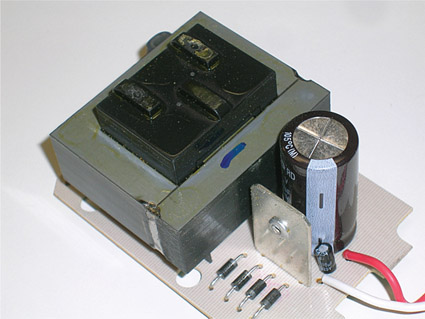
Figure 16.14
Example of a simple DC power adaptor.
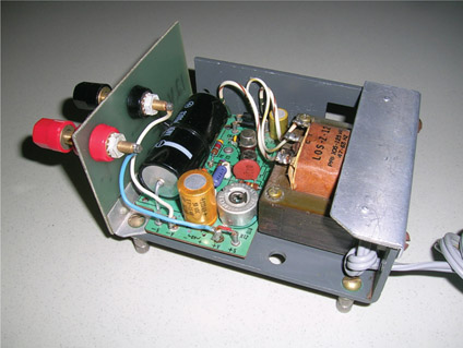
Figure 16.15
Example of a power adaptor with voltage regulation and protection circuits.
Remember that a capacitor reactance becomes smaller as the frequency increases. Consequently, at relative higher frequencies a capacitor can act as a conductor. For protecting an electronic device, or a component in a device, from overvoltage at relative higher frequencies a capacitor is often used in parallel with the item. Figure 16.16 shows an example. In this circuit all protective capacitors are in parallel with various components and bypass any higher-frequency voltage that might arrive. C1 is to protect the primary winding, and C2 does the same for the secondary winding. C11, C12, C21, and C22 are to protect the diodes. Notice that RB is added to this circuit, which is in parallel with the load. This resistor serves as a permanent load to the power supply. It is customary to have such a permanent load because it
- Provides a discharge path for the filter capacitor.
- Reduces the surge current and protects the diodes.
This resistor has a magnitude much larger than that of the load.
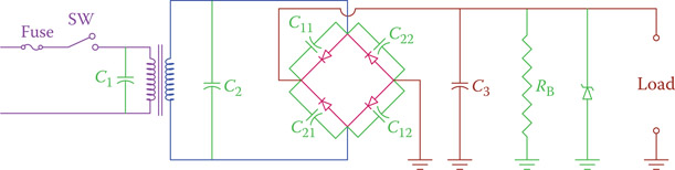
Figure 16.16
Protection and voltage regulation arrangements in a power adaptor.

Figure 16.17
DC power supply with positive and negative voltage.
In practice, the physical arrangement of the diodes does not need to be as shown in Figure 16.16. Here, for the sake of simplicity and similarity with the previous figures for a bridge rectifier, we have shown it this way. In Figure 16.17 a bridge rectifier is shown differently. But notice that the way the four diodes are connected still represents a bridge rectifier. The difference between Figures 16.16 and 16.17 is that in the latter the capacitor filters, the zener diodes and resistor RB are divided into two, and the middle point is grounded. In this way, a negative voltage (with respect to ground) is created and a power supply arranged this way can provide both positive and negative voltage. This is necessary for certain circuits.
16.8 More on Filters
The filters discussed so far have been used to take care of removing the ripple and smoothing the output voltage from a rectifier. There are other aspects of filters that we did not consider but were pointed out in Chapter 13. We are going to elaborate on these features.
The frequency of ripples in each of the preceding cases is constant. What if a general signal is made out of components at different frequencies? Examples of such a scenario are plenty. Speech and sound are good examples. The audible range of sound for a human being can be between 100 Hz and 20 kHz (though for most people the more realistic range is between 500 and 5000 Hz). If sound is converted to an electric signal through a microphone, the same frequencies in the sound appear in the electric signal. But, reproducing a recorded signal is not immune to noise from various sources.

Figure 16.18
Interchanging L and C in an L-type filter. (a) Capacitor is parallel with load. (b) Inductor is parallel with load (load is connected to the output).
Recalling the behavior of a capacitor or an inductor, their apparent resistance (reactance) changes with frequency. An inductor exhibits more reactance as the frequency increases, whereas for a capacitor, the opposite is true (a review of Chapter 8 before proceeding further on this section is recommended). We now consider the filter part of the previous circuits in this chapter and treat a filter as an input-output device. We further consider that we may have different ways of combining components to construct filters, as exemplified by the circuits in Figures 16.10 and 16.11.
Let start with the filter in Figure 16.10b, which is repeated in Figure 16.18a, and compare its behavior with that in Figure 16.18b. We are going to use the terms high- and low-frequency signals but bear in mind that high and low are relative to each other and do not refer to any particular value. You may assume that a high-frequency signal has a frequency 10 times larger than that in question.
16.8.1 High Pass and Low Pass Filters
In the circuit of Figure 16.18a for low-frequency signals the resistance exhibited by the reactance of the inductor is low, whereas for high-frequency signals this resistance is high. For the capacitor it is the reverse; for high frequencies the capacitor acts as a shorted connection (low resistance), but for low frequencies it has a relatively sizeable reactance value. The result of this behavior of the capacitor and the inductor is that if a combined signal consisting of high- and low-frequency components appears at the input terminal of this filter, the low-frequency components are passed to the output, whereas the high-frequency components are shorted to the ground and do not pass.
On the contrary, for the circuit shown in Figure 16.18b the opposite happens. The low-frequency signals are encountered by high resistance on the way because of the reactance of the capacitor. Additionally, the inductive reactance of the inductor is low, which leads to a low voltage across the output terminals. Therefore, the low-frequency signals are blocked from reaching the output, but the high-frequency signals pass. On the basis of their performance and the action on an input signal the filter in Figure 16.18a is called a low pass filter, and the one in Figure 16.18b is called a high pass filter.
Low pass filter: Type of electric filter that blocks the higher frequencies in a signal consisting of various frequencies and allows the lower frequencies to pass to the output.
High pass filter: Type of electric filter that blocks the lower frequencies in a signal consisting of various frequencies and allows the higher frequencies to pass to the output.
A filter selects or removes signals based on their frequency and based on the filter specification.
Another way of looking at what happens in the filters in Figure 16.18 is to consider them as voltage dividers. The input voltage is divided into two, one part across the component on the horizontal segment and one part across the component shown on the vertical segment and grounded. The output has the same voltage as the component on the vertical segment, which is a capacitor in the first filter and an inductor in the second filter. For high frequencies the output of the first filter is shorted; thus, this is a low pass filter. In a circuit as shown in Figure 16.18b the capacitor is shorted for high frequencies and the whole input voltage appears across the inductor; thus, it is a high pass filter. The inductor exhibits a large reactance to the high-frequency signal and does not short it to the ground.
Filters of other types exhibit similar behavior. Other high pass filters are shown in Figure 16.19, and other low pass filters are shown in Figure 16.20.

Figure 16.19
Other high pass filters. (a) T-type high pass filter. (b) π-type high pass filter.
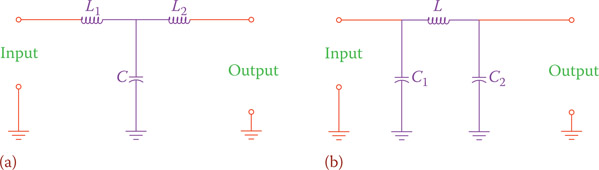
Figure 16.20
Other low pass filters. (a) T-type low pass filter. (b) π-type low pass filter.
The performance of any filter in passing high- or low-frequency signals and rejecting (or suppressing) the other ones can be shown by a curve. There is never a sharp line separating which frequencies will pass and which ones will be blocked because the distinction between high and low is relative and the transition is gradual. Figure 16.21 illustrates the transition. It shows the output voltage with respect to the change in frequency for a low pass filter. Similarly, Figure 16.22 depicts the behavior curve of a high pass filter. These two figures exhibit the typical forms of the associated curves. There are no numbers given either for the frequency or voltages. A particular filter (with values of the capacitance and inductance given) has a specific curve that reflects the frequencies that are on the pass side, those on the suppress side, and the ones in the transient region.
As we can see, a filter may never eliminate a signal by 100 percent. It reduces the strength or power of a signal by reducing its voltage or current (and thus the power associated with it). In the figures the voltage was used, but depending on a circuit, it could have been the current. The act of reducing the effect of a signal (i.e., suppressing a signal) is called attenuation. A high pass filter, for instance, has no or little attenuation of the high-frequency signals, but the low-frequency signals are attenuated to a great degree.
Attenuation: Reducing the intensity of an electric signal to match measurement and other devices.
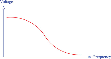
Figure 16.21
Typical characteristic curve of a low pass filter.
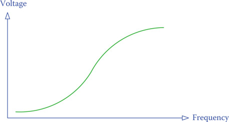
Figure 16.22
Typical characteristic curve of a high pass filter.
You notice that in all the aforementioned filters there are two elements that stand between the input and the output. Those are shown as “1” and “2” in Figure 16.23, which represents a general form of filters. For passing a signal from input to output, ideally, element 1 must have no resistance and element 2 must have zero current. On the contrary, for blocking a signal, element 1 must have significant voltage drop and element 2 must be short circuit (thus, no voltage across it).

Figure 16.23
General characteristic for (a) block a signal or (b) pass a signal behavior of filters.
16.8.2 Band Pass and Band Reject Filters
In addition to high pass and low pass filters, there are two more classes of filters: band pass and band reject. When inside a circuit, a band pass filter exhibits small or no resistance against current for signals within a finite range of frequencies and high resistance for other frequencies. As a result, all signals with frequencies in that range pass to the output. All other signals with frequencies outside of the range are affected, and their voltage level is reduced.
Band pass filter: Type of electric filter that lets signals in a range of frequencies pass from the input side to the output. All other signals with frequencies outside this range are blocked.
The opposite of band pass filter is band reject filter, which lets all signals with frequencies outside a particular range pass to the output, but those signals having frequencies within that range be blocked from reaching the output.
Band reject filter: Opposite of band pass filter. All the signals with frequencies in a defined range are blocked from reaching the output.

Figure 16.24
Typical characteristic curve of a band pass filter.
Bandwidth: Range of frequencies in a band pass or band reject filter.
Figure 16.24 depicts a characteristic curve of a typical band pass filter, and Figure 16.25 shows that of a band reject filter. The range of frequencies involved is called the bandwidth (BW) of a filter. The smaller a bandwidth is, the higher the selectivity of a filter in passing the desired frequencies or rejecting the unwanted signals.
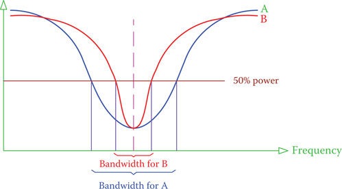
Figure 16.25
Characteristic curve of a band reject filter.
Band pass and band reject filters work based on the resonance frequency of a capacitor-inductor pair. We recall from Chapter 8 (see Section 8.13) that for an inductor and a capacitor, either in parallel or in series, there is a resonant frequency that can be determined from the values of inductance L and capacitance C. For each circuit we have observed a number of properties. A parallel LC circuit at resonance, especially when used in filters, is known as a tank circuit. At resonance, for a capacitor and an inductor forming a tank circuit the total current in their main circuit (not in the tank circuit that has a large local current) becomes minimum (see Section 8.13.2), meaning that the impedance of the branch containing the tank circuit is maximum. As a result, the voltage drop across the tank circuit is high.
Tank circuit: Part of an electric circuit consisting of an inductor and a capacitor in parallel with each other, used in filters.
On the contrary, at resonance the voltage drop across the series capacitor-inductor is minimum (see Section 8.13.1), implying that they (the capacitor and inductor together) have negligible impedance for the current flow. If a set of series capacitor-inductor and parallel capacitor-inductor combination having the same resonance frequency is used in a filter structure (L-type, π-type, and T-type), as shown in Figure 16.26, then the filter affects a band (range) of frequencies. All the filters in Figure 16.26 have the same behavior of a passing filter (based on Figure 16.23b) for a band of frequencies.
Figure 16.26 represents three designs for a band pass filter. If the parallel LC and the series LC blocks are swapped the result is a band reject filter. Figure 16.27 shows three different designs of band reject filters. In all circuits shown in Figures 16.26 and 16.27 the resonance frequency of the capacitor and inductor in parallel must be the same as the resonance frequency of those in series, so that the arrangement behaves as a band pass or band reject filter. A band reject filter is also called a band stop filter.
Band stop filter: Another name for band reject filter.
Note that the filters shown in Figures 16.26 and 16.27 are not the only designs for band pass and band reject filters. If the components in the horizontal segments (in L, T, and π) are removed, the remaining part still acts as a band pass or band stop filter.

Figure 16.26
Structures of band pass filters. (a) L-type. (b) T-type. (c) π-type.
For band pass and band reject filters the resonance frequency of the series inductor-capacitor and that of the parallel inductor-capacitor must be the same.
If the resonant frequency of the L and C components in a filter is denoted by fRes, the bandwidth for that filter is such that fRes is in the middle. The bandwidth is defined by two frequencies, one higher and one lower than fRes. The boundaries are determined by those frequencies for which the output voltage drops by about 30 percent. That is, the frequencies at which the output voltage will be 70.7 percent of the output voltage for resonance frequency. In Figures 16.24 and 16.25 the characteristics of two band pass filters A and B are shown. A line corresponding to 50 percent power denotes the 70 percent voltage output at resonance (since power is proportional to square of voltage, and 0.7072 = 0.5). Accordingly, the bandwidth for each filter is depicted on the basis of the intersections of the 50 percent power line and each curve.
The bandwidth of a filter depends on the so-called quality (or quality factor) Q of the inductor-capacitor used in its structure. The higher the value of Q, the narrower the bandwidth. Q is a number and has no unit. Higher value of Q implies better quality.
16.8.3 Quality Q
Bandwidth and quality (factor) are related to each other by
| BW=fResQ | (16.3) |
Thus, if the resonance frequency and the quality of a filter are known its bandwidth can be determined.
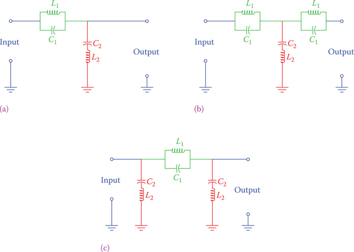
Figure 16.27
Structures of band reject filters. (a) L-type. (b) T-type. (c) π-type.
On the basis of the preceding discussions, a band pass or band reject filter is made of a set of capacitors and inductors, either in parallel or in series with each other. The quality of any filter, therefore, is defined by the quality of these two main elements.
Quality of a capacitor is normally high (based on leakage), and, consequently, the quality of a filter is determined by that of the inductor. Because in reality an inductor is a coil, it has some resistance in its wire winding, though it can be small. This resistance is shown as a resistor r in series with the inductor (note that we have shown this resistor with a lowercase to make it distinct from any other resistor R). Quality of an inductor is defined by the ratio of its reactance to its resistance, at any given frequency.
| Q=XLr | (16.4) |
For a filter XL is the reactance at the resonance frequency.
Example 16.1
Quality of a 3.3 μF capacitor is 300. This capacitor is used in a tank circuit at the output of a band pass filter. If the coil inductance and resistance are 1 mH and 0.4 Ω, respectively, find the bandwidth of the filter.
Solution
First, we find the resonance frequency for the capacitor and the inductor.
| fRes=12π√LC=1(2)(3.14)√(0.001)(0.0000033)=2770 Hz |
Then for the resonant frequency we find the inductor reactance
XL = (2)(3.14)(2770)(0.001) = 17.4 Ω
The value for inductor Q now can be determined
| QL=17.40.4=43.5 |
Because QL < QC = 300, the Q for the tank circuit is taken as that of the coil; thus, Q = 43.5, and the filter bandwidth is
| BW=277043.5=63.7≅64 Hz |
Thus, this filter affects the frequencies between 2738 and 2802 Hz.
Note that for the cases that the quality of the inductor is higher than the quality of the capacitor (like in the above example), Equations 16.3 and 16.4 can be combined together and the bandwidth can be defined in terms of the specifications of the inductor. In such a case,
| BW=r2πL | (16.5) |
16.9 Chapter Summary
- DC electricity can be obtained from AC using a rectifier.
- A single-phase half-wave rectifier eliminates the negative half of a full cycle of AC to obtain DC. It uses one diode.
- A single-phase full-wave rectifier uses two diodes, each one conducting for half of each cycle. Current through a load is always in one direction, as if all negative half cycles are converted to positive by the rectifier.
- A single-phase bridge rectifier has an output like a full-wave rectifier. It uses four diodes, each pair conducting for half of a cycle. It is the most commonly used single-phase rectifier.
- A three-phase bridge rectifier uses six diodes.
- Fluctuations in the voltage of DC electricity from a rectifier is called ripple.
- Ripples are undesirable, and for many applications they must be removed or smoothed out.
- Frequency of ripples in a rectifier output depends on the type of rectifier.
- Ripples are removed or their intensity is reduced by filters.
- Capacitors and inductors are the main components for filtering.
- L filters, T filters, and π filters are the most common filters.
- Filters are also used for separating signals of different frequencies.
- A low pass filter delivers low-frequency signals and blocks high-frequency signals from reaching its output.
- A high pass filter delivers higher-frequency signals to its output and blocks lower-frequency signals.
- A band pass filter delivers the signals within a range of frequencies and blocks all signals with other frequencies from reaching its output.
- The function of a band reject filter is opposite to the band pass filter and allows all signals except those within a particular frequency range to pass to the output.
- The bandwidth of a filter is all those frequencies between two bounds, which a filter is able to separate from the rest.
- The bandwidth of a filter is inversely proportional to the quality of a filter. The higher the quality is, the narrower the bandwidth.
- The quality of a tank circuit is dominated by quality of the inductor.
- Filters are used also to remove noise from measured signals.
Review Questions
- Describe how AC is converted to DC.
- What is the principal function of a rectifier?
- Why do we need rectifiers?
- What is the main component of a rectifier?
- What is ripple and how is it coming into DC?
- How can one reduce ripples?
- What is the difference between a half-wave rectifier and a full-wave rectifier?
- What is the difference between a full-wave rectifier and a bridge rectifier?
- What is meant by filtering?
- What are the main components of filters?
- How many diodes are used in a single-phase bridge rectifier?
- How many diodes are used in a three-phase bridge rectifier?
- Draw the schematic of a single-phase bridge rectifier.
- Draw the schematic of a three-phase bridge rectifier.
- What is the difference between a filter in a rectifier as shown in Figure 16.16 and one shown in Figure 16.20?
- What is the difference between a low pass filter and a high pass filter?
- What is meant by band in a band pass or band reject filter?
- What components do you need to make a 12 V DC power supply?
- If you construct a power supply, can you use it to start your car with? Why or why not?
- Can you charge the battery of your car with the power supply in the previous question?
- Can you say that a band pass filter is made up of a low pass filter and a high pass filter? Why or why not?
- What is the difference between a band pass filter and a band reject filter?
- What is the bandwidth of a filter?
Problems
- For the circuit shown in Figure 16.1, draw the output voltage if the direction of the diode is reversed.
- In a bridge rectifier, what happens if the direction of all diodes is reversed?
- What happens in a three-phase rectifier if three of the diodes from one side are removed?
- What is the bandwidth of a 0.1 mH coil if used in a tank circuit with a 4.7 μF capacitor? The resistance of the coil is 0.5 Ω. The capacitor quality is sufficiently high.
- Referring to Figures 16.6 and 16.7, determine the percentage ripple ratio in each case.