 Appendix G: Structure of Logic Gates
by Ahmad Hemami
Electricity and Electronics for Renewable Energy Technology
Appendix G: Structure of Logic Gates
by Ahmad Hemami
Electricity and Electronics for Renewable Energy Technology
- Cover
- Half Title
- Title
- Copyright
- Dedication
- Contents
- Preface
- Acknowledgments
- Author
- 1 Energy and Electricity
- 2 Basic Mathematics and Systems of Measurement Units
- 2.1 Introduction
- 2.2 Ratio and Percentage
- 2.3 Area and Volume Ratios
- 2.4 Angles, Triangles, and Trigonometric Relationships
- 2.5 Principal Measurement Entities and Systems of Measurement
- 2.6 Other Measurement Entities and Their Derivation
- 2.7 Conversion between Systems of Measurement Units
- 2.8 Formulas, Relationships, and Equations
- 2.9 Chapter Summary
- 3 Atomic Structure of Materials
- 3.1 Introduction
- 3.2 Material Properties
- 3.3 Atom and Molecule
- 3.4 Atomic Structure of Materials
- 3.5 Differences between Materials
- 3.6 Similarities between Materials Based on Valence Electrons
- 3.7 Categorization of Materials: Conductors and Insulators
- 3.8 Electric Charge and Energy in Electrons
- 3.9 Chapter Summary
- 4 DC and AC Electricity
- 5 Voltage, Current, and Power
- 5.1 Introduction
- 5.2 Electric Current
- 5.3 Electric Voltage
- 5.4 Ohm’s Law: Relationship between Voltage, Current, and Load Resistance
- 5.5 Measuring Electric Current
- 5.6 Measuring Electric Voltage
- 5.7 Multimeter
- 5.8 Measuring Resistance
- 5.9 Electric Power
- 5.10 Measuring Electric Power and Energy
- 5.11 Chapter Summary
- 6 DC Circuits Relationships
- 6.1 Introduction
- 6.2 Series Circuit
- 6.3 Resistors in Series
- 6.4 Parallel Circuit
- 6.5 Resistors in Parallel
- 6.6 Combined Series and Parallel Resistors
- 6.7 Rule of Series Circuits
- 6.8 Rule of Parallel Circuits
- 6.9 Examples of Combined Circuits
- 6.10 Voltage Divider
- 6.11 Capacitors in DC Circuits
- 6.12 Inductors in DC Circuits
- 6.13 Power in DC Circuits
- 6.14 Chapter Summary
- 7 DC Motors and Generators
- 8 AC Circuits Relationships
- 8.1 Introduction
- 8.2 Vectors
- 8.3 AC Circuit Measurements and Values
- 8.4 Resistors in AC Circuits
- 8.5 Inductors in AC Circuits
- 8.6 Capacitors in AC Circuits
- 8.7 Power in Inductors and Capacitors
- 8.8 Phase Difference
- 8.9 Power in AC
- 8.10 Series RLC Circuits
- 8.11 Parallel RLC Circuits
- 8.12 Voltage Divider in AC Circuits
- 8.13 Resonance
- 8.14 Power Factor Correction
- 8.15 Chapter Summary
- Advanced Learning: AC Problem Solving Using Complex Numbers
- 9 Three-Phase Systems
- 9.1 Introduction
- 9.2 Three-Phase Electricity
- 9.3 Properties of a Three-Phase System
- 9.4 Load Connection in Three-Phase Systems
- 9.5 Three-Phase Loads
- 9.6 Use of Vectors in Three-Phase Electricity
- 9.7 Unbalanced Loads
- 9.8 Chapter Summary
- Advanced Learning: Mathematical Representation of Three-Phase Systems
- 10 Transformers
- 10.1 Introduction
- 10.2 An Illustrative Example
- 10.3 Single-Phase Transformer
- 10.4 Ideal Transformer
- 10.5 Autotransformer and Isolation Transformer
- 10.6 Transformer Mounting
- 10.7 Three-Phase Transformers
- 10.8 Transformer Applications and Power Rating
- 10.9 Transformer Efficiency
- 10.10 Transformer Circuits
- 10.11 Chapter Summary
- Advanced Learning: Real Transformer Circuit Analysis
- 11 AC Motors and Generators
- 12 Electric Power Transmission and Distribution
- 12.1 Introduction
- 12.2 Power Transmission and Distribution
- 12.3 Electric Cables
- 12.4 Fault Detection and Protective Measures
- 12.5 Transmission Lines
- 12.6 Rules for Network Problems
- 12.7 High Voltage Direct Current Transmission
- 12.8 Chapter Summary
- Advanced Learning: Positive, Negative, and Zero Sequence for Fault Analysis
- 13 Electronic Components, Functions, and Devices
- 14 Diode
- 15 Regulating Diodes and Applications
- 16 Diode Rectifiers and Filters
- 17 Transistor
- 17.1 Introduction
- 17.2 Junction Transistor
- 17.3 Transistor Size and Packaging
- 17.4 Transistors Connection and Biasing Configuration
- 17.5 Modes of Operation
- 17.6 How a Transistor Works
- 17.7 Transistor Properties
- 17.8 Transistor Main Functions
- 17.9 Transistor as a Switch
- 17.10 Transistor Amplifier
- 17.11 Biasing a Transistor
- 17.12 Chapter Summary
- 18 Transistor Circuits
- 18.1 Introduction
- 18.2 Transistor Characteristic Curves
- 18.3 Common-Emitter Amplifier
- 18.4 Common-Base Amplifier
- 18.5 Common-Collector Amplifier
- 18.6 Current Gain, Voltage Gain, and Power Gain in Amplifiers
- 18.7 Amplifier Classes
- 18.8 Input and Output Impedance
- 18.9 Coupling and Impedance Matching
- 18.10 Testing Transistors
- 18.11 Chapter Summary
- 19 Switchable Diodes and Gated Transistors
- 20 Power Converters
- 21 Electronic Power Converters in Wind Turbines and Solar Photovoltaic Systems
- 22 Digital Electronics
- 23 Logic Circuits and Applications
- 24 Encoders and Decoders
- Glossary
- Appendix A: Internal Resistance of Batteries and Battery Aging
- Appendix B: Switches
- Appendix C: Special Transformers
- Appendix D: Mil and Circular Mil
- Appendix E: Standard Resistors
- Appendix F: Quality Factor of RLC Circuits
- Appendix G: Structure of Logic Gates
- Index
Appendix G: Structure of Logic Gates
It was mentioned in Chapter 22 that all the digital electronics components are made out of analog electronic circuits, such as transistors. Construction of some of the logic gates are shown in Figures G.1 and G.2. These are the simplest designs, which are based on transistor-transistor logic. Other designs are also possible. Furthermore, the basic designs can be enhanced by amplification.
Figure G.3a depicts a simple transistor working as a NOT circuit. An enhancement of the same circuit with another transistor to amplify the input is shown in Figure G.3b. Also, another version of the NOR gate is illustrated in Figure G.3c. However, the previous one in Figure G.2b is preferable to this in the sense that the two inputs cannot have interaction with each other, so that one influences the other (when one is high and the other is low). A XOR gate is more involved and can be synthesized from other gates.
In practice, logic gates come as packages in the form of integrated circuit (IC). For example, the family of 74xx IC’s is a series of logic gates and other digital devices all defined by the number 74 and some other characters and numbers. Figure G.4 shows the inside structure and the pin-out of a sample called 7486, which contains four two-input XOR gates.

Figure G.1 Structure of (a) AND and (b) OR gates from transistors.
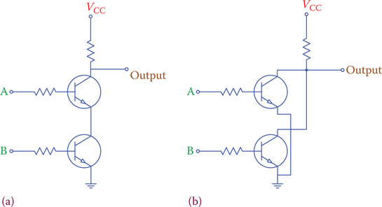
Figure G.2
Structure of (a) NAND and (b) NOR gates from transistors.
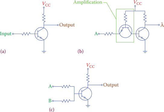
Figure G.3
(a) NOT gate, (b) NOT gate with input amplification, and (c) alternative NOR gate.

Figure G.4 Layout of four XOR gates in 7486 IC.
-
No Comment