
6
DC Circuits Relationships
OBJECTIVES: After studying this chapter, you will be able to
- Explain series circuits
- Understand the equivalent resistor in series resistors
- Explain parallel circuits
- Understand the equivalent resistor in parallel resistors
- Explain combined series and parallel circuits
- Understand the equivalent resistor for a set of resistors combined together in series and parallel
- Use a voltage divider for providing a desired voltage
- Perform power calculations for all DC circuits
- Describe the behavior of a capacitor when in a DC circuit
- Describe the behavior of an inductor in a DC circuit
- Understand what “time constant” in an electric circuit is
New terms: Combined circuit, equivalent resistor, parallel circuit, series circuit, time constant, voltage divider
6.1 Introduction
Not all electric circuits are composed of a simple device and a single loop. Circuits can have more of the same component put together or they can have any number of the basic components put together in various combinations. This could be because of different parts of the same device or when a source is feeding various devices. For instance, at home there is only one source of electricity, whereas many devices are powered by the same source. This is true for all the electric devices, say in a factory, which are ultimately powered by one source of electric power.
If we learn how to deal with a few components when put together, then we will be able to extend that to the case when thousands of components are put together. The application of what you learn here is widespread. At small scale, consider few components, like in a stove that has a few heating elements, a light and so on, or in a battery charger (Chapter 16). At large scale, consider a city where each house has several devices (e.g., lights, radio, TV, kitchen appliances). Today, electricity in cities is provided by more than one source. The power network, or grid, is fed at different points. So, we need to study the cases where there is more than one power source.
In this chapter we discuss how to deal with such circuits when connected to a DC source. In Chapter 8 we discuss these combinations in AC circuits.
6.2 Series Circuit
When a number of components are put together in such a way that when connected to a source they form a single loop, we say these components are in series (with each other), and the circuit formed this way is called a series circuit. A series circuit is shown in Figure 6.1. In this circuit, there are three resistors (or resistive components) and two inductors in series and connected to 110 V. A switch is added for turning the power on and off. Note that it is not defined if the 110 V source is DC or AC (when no other information is included). In the case it was DC we could show the source by a symbol for battery, and in the case it was an AC source we could write 110 VAC (when an AC source is used, normally the frequency should also be given).
Series circuit: Type of electric circuit in which the loads form a single loop between the two terminals of the power source.
Because there is only one loop, there is only one current for all the components. This is a property of a series circuit.
To analyze this circuit (finding the current, power, etc.), it is first necessary to reduce this circuit. The first step will be to substitute all the components of the same type by a single component equivalent to all those. This is what is always pursued (for parallel and combination circuits, as well).
In this chapter we discuss only finding the equivalent circuit for resistors. To determine the equivalent component for inductors and capacitors, refer to Chapter 8.
In a series circuit, all components in series with each other have the same current.
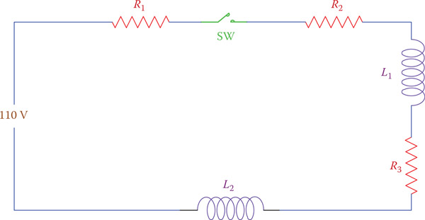
Figure 6.1
A general series circuit.
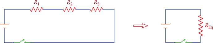
Figure 6.2
Resistors in series must be reduced to their equivalent resistor.
6.3 Resistors in Series
Resistors in series are shown in Figure 6.2, which contains only three resistors, but, in general, it could be any number. Any such circuit must be simplified to the equivalent circuit, which contains only one resistor. The equivalent resistor, denoted by REq, or often just R, for a series circuit is
| REq=R=R1+R2+R3+… | (6.1) |
Equivalent resistor: Resistor that can replace two or more resistors in series, parallel, or in any combination, that is, having the same effect on the circuit.
Example 6.1
What current is in a circuit containing three resistors connected to a 12 V battery if two of the resistors are 5.1 Ω each and the third one is 51 Ω?
Solution
First, we find the equivalent resistor, as
R = 5.1 + 5.1 + 51 = 61.2 Ω
The current can be determined (from Equation 5.2)
I = 12 ÷ 61.2 = 0.196 A ≈ 0.2 A
Example 6.2
In the following circuit, what current is in the 800 Ω resistor (see Figure 6.3)?
Solution
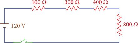
Figure 6.3
Resistors in Example 6.2.
The current in the 800 Ω resistor is the same as in the other resistors. First, find the equivalent resistor:
R = 100 + 300 + 400 + 800 = 1600 Ω
and the current is calculated as
I = 120 ÷ 1600 = 0.075 A
Alternatively, you may directly find the current from
| I=120(100 + 300 + 400 + 8000)=0.075 A = 75 mA |
Which way is easier for you depends on your habit and how familiar you are with your calculator.
Example 6.3
In the circuit of Example 6.2, what voltage is across the 800 Ω resistor?
Solution
Using Equation 5.1, the voltage across this resistor is
V800 = (800)(0.075) = 60 V
Note the subscript 800 is used for the voltage in order to denote the voltage across the 800 Ω resistor.
Note also that we may say the voltage difference across the 800 Ω resistor is 60 V. Either term is correct to use and implies that if a voltmeter is connected to the two sides of the resistor, it should read 60 V. Furthermore, if the two ends of the resistor are called A and B, we may say the voltage difference between A and B is 60 V.
Example 6.4
Current in a device must not exceed 4 A. This device has a resistance of 24 Ω. If the available voltage is 115 V, determine the resistance of a resistor to be put in series with this device, so that the current is 4 A.
Solution
Voltage that causes a current of 4 A to flow in the device is
V = RI = (24)(4) = 96 V
The remainder of the voltage from the source is
115 − 96 = 19 V
Because this resistor must also carry 4 A current, its resistance is
19 ÷ 4 = 4.75 Ω
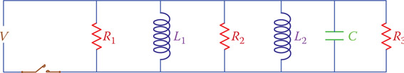
Figure 6.4
Example of a parallel circuit.

Figure 6.5
Although this is equivalent to Figure 6.4, the circuit is almost never shown this way.
6.4 Parallel Circuit
In a parallel circuit all the components are directly connected to the electric source. In this way, the full voltage of the source is applied to all the components in the circuit. A parallel circuit is normally shown as in Figure 6.4. You see that each component in the circuit makes a separate loop containing the source. You may show the parallel circuit of Figure 6.4 as shown in Figure 6.5 (i.e., the components are shown both sides of the source), but this is almost never done, although the two circuits represent the same thing.
Parallel circuit: Electric circuit having two or more electric components with their terminals connected to the same point in the circuit, so that current divides between the branches formed by those components.
In a parallel circuit each loop containing the source has a current, which is independent of the currents in the other loops. In this sense, in a parallel circuit there is not a common current for all the components, but the applied voltage to all the components in parallel is the same. Moreover, as can be observed, the current through the source is the sum of all the currents through the various components in the circuit. A source must be capable of delivering the total current required by all the loads.
Here again in order to find the current and determine the power requirement from the source all components of the same type are substituted by their equivalent component. We study parallel resistors in this chapter but leave the study of equivalent inductor and capacitor for Chapter 8.
In a parallel circuit all the components in parallel with each other have the same voltage.
6.5 Resistors in Parallel
Figure 6.6 illustrates three resistors R1 to R3 in parallel. These resistors can be substituted by a single resistor that is equivalent to all those resistors. The formulation for finding the equivalent resistor for three parallel resistors can be generalized and extended to embrace as many that can be in parallel.
Because each branch (resistor) in Figure 6.6 has a separate current, we can identify the currents for R1 to R3 as I1, I2, and I3, respectively. Then the total current in the circuit, that is, the current that must be provided by the power supply, is
| I=I1+I2+I3 | (6.2) |
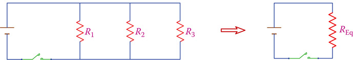
Figure 6.6
Resistors in parallel are substituted by a single equivalent resistor.
According to Ohm’s law, the values of the various currents in Equation 6.2 are
| I1=VR1, I2=VR2, I3VR3, I=VR=VREq |
because the voltage V is the same for all branches and for the equivalent resistance. Note that for simplicity the subscript Eq is dropped from REq, and only R is used for the equivalent resistor.
Substituting for I1, I2, I3, and I in Equation 6.2 leads to
| VR=VR1+VR2+VR3 |
which leads to
| 1R=1R1+1R2+1R3 | (6.3) |
This is the relationship between parallel resistors. Note that in Equation 6.3 the value of R obtained this way is smaller than any of the R1 to R3 values. Equation 6.3 gives the inverse value of R.
Thus, R can be found from (inverting both sides of Equation 6.3)
| R=11R1+1R2+1R3 | (6.4) |
In the case there are only two resistors, Equation 6.4 can be simplified to
| R=R1R2R1+R2 | (6.5) |
Example 6.5
If four 1000 Ω resistors are connected in parallel, what is the resistance value of the equivalent resistor?
Example 6.6
A 510 Ω and a 51 Ω resistor are put in parallel. What is the resulting resistor?
Solution
Because there are only two resistors, one can directly use Equation 6.5
| R=510 × 51510+51=26,010561=46.36 Ω |
Note that the equivalent resistor is smaller than the 51 Ω. If in calculation you ever came up with a number larger than the smallest resistor in the parallel resistors, check your calculation because a mistake has happened.
Example 6.7
Resistance of the equivalent resistor for a 47 Ω resistor parallel with another resistor is 15 Ω. What is the resistance of the second resistor?
Solution
We may employ Equation 6.3 and write
| 115=147+1R2 |
From which we may find R2
| 1R2=115−147=0.04539→R2=22 Ω |
Note that the values for resistors in the above examples are among those of the standard resistors (see Appendix E for standard resistors).
It is very helpful to notice that when similar resistors are put in parallel, the resistance of the ensemble is obtained from dividing their common resistance value by the number of units. For instance, if four 1000 Ω resistors are in parallel, they are equivalent to a 250 Ω resistor (see Example 6.5), and the resultant of two 51 Ω resistors is 25.5 Ω. Because 25.5 Ω is not a standard resistor, if one needs to use a resistance of this value in a circuit, one way is to use two 51 Ω resistors in parallel with each other.
6.6 Combined Series and Parallel Resistors
Arrangement of the components in a circuit can be in such a way that it may not be modeled either as a series circuit, or as a parallel circuit. The resistors in the circuit of Figure 6.7 illustrate a simple example. This circuit has components that are in series (have a common current) and components that are in parallel (a few branches start from some points). In other words, all components neither have the same current nor voltage across all components. Note that the way various resistors (and, in general, various components) are shown in Figure 6.7 is not the only way to represent this circuit. For example, the same circuit can be shown as in Figure 6.8. It is better to reduce the representation of a circuit to its simplest form, before anything else, because it helps to understand and analyze the circuit better. Often, it is an art to bring a complicated circuit to its simplest representation. Always we have to bear in mind that two components are in parallel if the same voltage is applied to them, and two components are in series if they are part of the same loop and share the same current.
The way to tackle a combined circuit (find the current, power, etc.) depends on the way the components are laid out. In the circuits of Figure 6.8 it is easy to understand that first we may replace the resistors R1 and R2 by their equivalent resistor and also resistors R3 and R4 by their equivalent resistor. Then we end up with three resistors that are in series with each other. The rules of resistors in series can, then, be applied.
Combined circuit: Circuit having a number of the same electric components in both series and parallel at the same time.
Two components are in parallel if the same voltage is applied to them, and two components are in series if they are part of the same loop and share the same current.

Figure 6.7
Example of a combined circuit.
Figure 6.9 shows another example of a combined circuit. It is a little more involved than the one in Figures 6.7 and 6.8. Dealing with a combined circuit of resistors requires, in general, that we find the single resistor equivalent to all those in the circuit. Nevertheless, before doing so, we need to know what the purpose of this analysis is and avoid unnecessary computations.

Figure 6.8
Alternative representation of the same circuit shown in Figure 6.7.
As said before, reducing combined resistors to their single equivalent resistor depends on the circuit. Step by step and from inside out we need to replace the parallel resistors by their equivalent resistor and the series resistors by their equivalent resistor. For instance, to reduce the circuit of Figure 6.9, the following steps are necessary:
- Substitute the parallel resistors R2 and R3 by their equivalent resistor R23.
- Substitute the series resistors R1 and R23 by their equivalent resistor R123.
-
Substitute the parallel resistors R5 and R6 by their equivalent resistor R56.
The result of these operations is shown in Figure 6.10.
The circuit of Figure 6.10 is still a combined circuit. Thus we need to further do the following.
- Substitute the parallel resistors R123 and R4 by their equivalent resistor R1234.
Now we have only three resistors R1234, R56, and R7 that are in series with each other, as shown in Figure 6.11. The equivalent resistor for these can be found now by adding the values of these resistors (Equation 6.1).
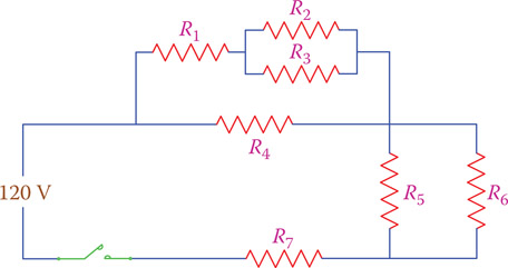
Figure 6.9
Another example of a combined circuit (more involved than that in Figure 6.7).

Figure 6.10
Result of operations 1 to 3 to the circuit of Figure 6.9.
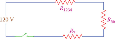
Figure 6.11
Simplification after steps 1 to 4 for the circuit in Figure 6.9.
Example 6.8
Find the equivalent resistance for the circuit of Figure 6.9, if R1 = 240 Ω, R2 = 300 Ω, R3 = 470 Ω, R4 = 510 Ω, R5 = 300 Ω, R6 = 300 Ω, and R7 = 2400 Ω.
Solution
Following steps 1 to 4 as mentioned above leads to
- Using Equation 6.5,
R23=300 × 470300+470=183.12 Ω - R23 is in series with R1
R123 = 240 + 183.12 = 423.12 Ω
- R56 is the resultant of R5 and R6 in parallel. However, since both are 300 Ω their equivalent resistance is 150 Ω.
- R123 is in parallel with R4; thus,
R1234=423.12 × 510423.12+510=231.26 Ω
Finally, the equivalent resistance of R1234, R56, and R7 is
R = 231.26 + 150 + 2400 = 2781.26 Ω ≈ 2781 Ω
In Example 6.8, how much total current is in the circuit that the power supply must provide?
Solution
Because all the resistors can be substituted by a single resistance of 2781 Ω, the total current that the power supply must be able to provide is
120 ÷ 2781 = 0.043 A = 43 mA
Often in a circuit, like that under study, it is necessary to find the current in all or some of the resistors. For this task, an additional calculation is necessary. In the problem of Example 6.8, the current in resistor R7 is the same as the total current as calculated, because R7 is a part of the resistors in series with each other in the final calculation. However, if the current in any other resistor is required, it is not readily available without some more analysis. The general way to do so is employing Ohm’s law for various parts of the circuit, as required. In this sense, if the current in a resistor is required, we need to have the voltage across the resistor (and divide by the value of the resistor). For example, if we need to know the current in resistor R4 in the Example 6.8, we must determine the voltage across it, first.
Before we can go ahead with how to perform this task, we must discuss two rules, one for the series circuits and one for the parallel circuits.
6.7 Rule of Series Circuits
As we have discussed, all the components in a series circuit have the same current, but there are different voltages associated with a number of components in series. Figure 6.12 shows three resistors in series with each other and the voltage measured between their ends is V (any number of items can considered; three is randomly selected).
Because there are three resistors, three voltages can be defined denoted by V1, V2, and V3 in Figure 6.12; if the circuit current is I, then
V1 = R1I, V2 = R2I, V3 = R3I
The rule of series circuits states that
| V=V1+V2+V3 | (6.6) |
That is, the sum of all the voltages across the components is equal to the supply voltage.
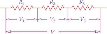
Figure 6.12
Three resistors in series under an applied voltage V.
If a 240 Ω resistor and a 510 Ω resistor are in series and are connected to a 12 V battery with wires of negligible resistance (say, 0.5 Ω, which is negligible compared to 240 Ω), what voltage is across the 510 Ω resistor?
Solution
We need to find the current first. The common current in both resistors is
| I=12240+510=0.016 A |
The voltage across the 510 Ω resistor is
V510 = (510)(0.016) = 8.16 V
Example 6.11
If the current through three resistors in series with each other is 0.06 A and the resistance of the resistors are 470 Ω, 680 Ω, and 750 Ω, what is the applied voltage to the three resistors?
Solution
Applied voltage can be found from
V = (470 + 680 + 750)(0.06) = (1900)(90.06) = 114 V
Alternatively, we may find the individual voltages and add them together
V1 = (470)(0.06) = 28.2 V
V2 = (680)(0.06) = 40.8 V
V3 = (750)(0.06) = 45 V
V = 28.2 + 40.8 + 45 = 114 V
In a series circuit the sum of all the voltages across the components (or voltage drops in the components) is equal to the total circuit voltage.
Example 6.12
In the circuit shown in Figure 6.13, find the value of R3.
Solution
From Ohm’s law the value for resistance R3 can be found if the voltage across it and its current are known. The voltage across R3 is found to be
V3 = 24 − (15 + 6) = 3 V
and the current through R3 is the same as that through the 120 Ω resistor, which is
I = 6 V ÷ 120 Ω = 0.05 A
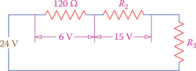
Figure 6.13
Example 6.12.
Thus,
R3 = 3 ÷ 0.05 = 60 Ω
Note that, alternatively, you could deduce that since the voltage across the 120 Ω resistor is 6 V, the resistance of R3 must be 60 Ω, because the voltage across it is 3 V. This proportionality is always true for the voltage across series components. In general, we may say that for two resistors in series the voltage across the larger resistor is larger than the voltage across the smaller resistor.
For two series resistors the voltage across the larger resistor is larger than the voltage across the smaller resistor.
6.8 Rule of Parallel Circuits
In a parallel circuit, there are as many independent currents as there are branches, in the same way that in a series circuit, there are as many independent voltages as the number of components. Independent is used, because there are also currents that are dependent on the other currents and can be obtained by adding or subtracting from each other, as shown in Figure 6.14.
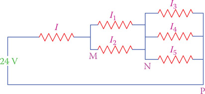
Figure 6.14
Different currents in branching (parallel) resistors.
As marked in Figure 6.14, there are various currents in any circuit containing parallel components. There exist, however, some relationships between these currents. These relationships can be found from the rule of parallel circuits. For more complicated circuits containing more than one source, other rules such as Kirchhoff’s current law must be employed (see Section 12.6.2).
The simple rule of parallel circuits that you need to understand is that when a current carrying line divides into two or more parallel branches the current in that line divides between the branches. This is well illustrated in Figure 6.14. Current I divides into I1 and I2. Thus,
| I1+I2=I | (6.7) |
Also, the two currents I1 and I2 branch into three divisions carrying I3, I4, and I5. In this sense,
| I3+I4+I5=I1+I2=I | (6.8) |
Example 6.13
In the circuit of Figure 6.15, I = 1.5 A and the current in R2 is 0.5 A. What current is in R1?
Solution
Because the sum of the currents I1 and I2 is 1.5 A and I2 is 0.5 A, thus,
I1 = 1 A
Example 6.14
In the circuit shown in Figure 6.16 the voltage difference between points A and B is 9 V. What is the current in R1 = 90 Ω and R2 = 180 Ω?
Solution
Current in R1 = 9 ÷ 90 = 0.1 A
Current in R2 = 9 ÷ 180 = 0.05 A
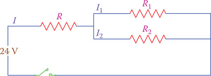
Figure 6.15
Circuit of Example 6.13.
Note the important fact that because the voltage across the two resistors is the same (being in parallel), the current in the 90 Ω resistor is twice as much as the current through the 180 Ω resistor. In general, we may say that when two resistors are parallel, the current in the smaller resistor is larger than the current in the larger resistor.

Figure 6.16
Circuit for Example 6.14.
In two parallel resistors the current in the smaller resistor is larger than the current in the larger resistor.
6.9 Examples of Combined Circuits
In dealing with combined circuits, there is no unique method of analysis. Depending on the circuit and what information is required, one must determine the simplest way. Also, more than one method of solution might be found for certain problems. The general approach of reducing the parallel and series circuits to their respective equivalents must be successively followed. In this section a number of examples are solved to illustrate the matter.
Example 6.15
In the problem of Example 6.13, what is the resistance of resistor R if the voltage across R2 = 9 V and the circuit current is 0.15 A?
Solution
Current through R is given (0.15 A), and the voltage across R can be determined from the other information given:
Voltage across R = VR = 24 − 9 = 15 V (from series circuit rule)
and the resistance of R is
R = 15 ÷ 0.15 = 100 Ω
Example 6.16
In the circuit of Figure 6.15, R = 10 Ω, R1 = 9 Ω, and R2 = 18 Ω. What is the current in R1 if the circuit current is 1.5 A?
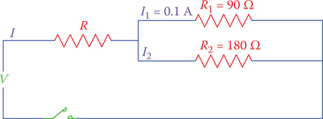
Figure 6.17
Circuit of Example 6.16.
Solution
VR = RIR = (10)(1.5) = 15 V
VR1 = VR2 = 24 − 15 = 9 V
IR1 = VR1 ÷ R1 = 9 ÷ 9 = 1 A
Example 6.17
In the circuit of Figure 6.17, if R = 36 Ω, what is the supply voltage?
Solution
Using Figure 6.17, the current in R1 is 0.1 A. Because R1 and R2 are in parallel, the current through R2 is 0.05 A (R2 is twice in size as R1). Thus, the total current in the circuit is 0.15 A.
Supply voltage is the sum of the voltage across R and the voltage across the parallel resistors.
Voltage across R = (36)(0.15) = 5.4 V
Voltage across R1 and R2 = (90)(0.1) = 9 V
Supply voltage = 5.4 + 9 = 14.4 V
Example 6.18
The circuit in Figure 6.18 is the same as that in Figure 6.9, shown differently. (It might look different, but it is the same). If R1 = 240 Ω, R2 = 300 Ω, R3 = 470 Ω, R4 = 510 Ω, R5 = 300 Ω, R6 = 300 Ω, and R7 = 2400 Ω, the total current was found (see Examples 6.8 and 6.9) to be approximately 43 mA. How much current is in R4?
Solution
To find the current in R4, we need to determine the voltage across it, first. If the voltage across R7 and the voltage across R5 (or R6) can be subtracted from the supply voltage, then the voltage across R4 can be determined.
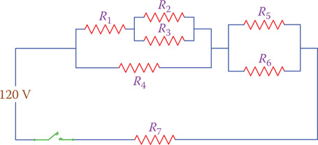
Figure 6.18
Circuit of Example 6.18.
VR7 = R7I = (2400)(0.043) = 103.2 V
In finding the voltage across R5 and R6 we need to use their equivalent value R56 if the 43 mA current is to be used.
VR5 = VR6 = R56I = (150)(0.043) = 6.45 V (see Example 6.8)
VR4 = 120 − (103.2 + 6.45) = 120 − 109.65 = 10.35 V
IR4 = VR4 ÷ R4 = 10.35 ÷ 510 = 0.020 A = 20 mA
Example 6.19
In the problem of Example 6.18, what is the power consumption of R2?
Solution
To find the power in R2, either the voltage across it or the current in it must be known (in addition to its resistance). If we concentrate on the part of the circuit containing R1, R2, R3, and R4, we recall from Example 6.8 that the circuit was reduced to that of Figure 6.10. Because the total current is 43 mA and the current in R4 is 20 mA (from Example 6.18), the current in R123 is 23 mA (43 − 20).
From the fact that the voltage across R4 (and R123) is 10.35 V (see Example 6.18) and the current in R123 is 23 mA, we can conclude that the voltage across R2 and R3 in the original circuit is
| 10.35−(R1)(0.023)=10.35−(240)(0.023)=10.35−5.52=4.83 V |
Power consumption of the resistor R2 can now be directly found from Equation 5.6:
| P=V2R=4.832300=0.07776 W = 77.76 mW |
6.10 Voltage Divider
A voltage divider is a circuit composed of series components that is used to provide one or more voltages from a single voltage supply. These voltages are lower than that of the power supply. This is not the most efficient way of obtaining a desired voltage from a power supply, but it is often the simplest or the easiest way. Suppose that you need 7.5 V for an application, but you have 12 V power supply. In such a case you may use a voltage divider to obtain 7.5 V from 12 V.
Voltage divider: Electric circuit made up of components in series that can deliver two or more smaller voltages from a voltage applied to the circuit.
Figure 6.19 depicts the arrangement of a voltage divider. This voltage divider is made out of three resistors. On the basis of the voltage of the power supply and the values of the resistors, a current passes through all the resistors. Then various voltages can be observed between points A-B, A-C, B-C, and B-D in addition to the supply voltage V across A-D. The load is connected between the appropriate points across a resistor, based on the desired voltage. One important fact about the use of voltage dividers is that the load resistance cannot be small compared to the resistor across which it is connected. Otherwise, the voltage relations will not remain as desired. As a rule of thumb, you may say the resistance of the load must be 10 times or more larger than the resistance of the resistor to which it is connected.
Various voltages that are available from a voltage divider can be directly found from the values of the resistors and the supply voltage. For instance, for the voltage divider in Figure 6.19, we may write the following relations. This formulation is general and can be used for any voltage divider.
| VAB=V × R1R1+R2+R3VBC=V × R2R1+R2+R3VCD=V × R3R1+R2+R3 | (6.9) |
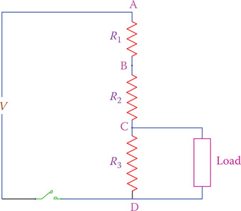
Figure 6.19
Voltage divider.
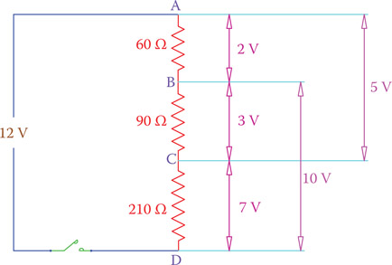
Figure 6.20
Getting different voltages from one source with a voltage divider.
| VAC=V × R1+R2R1+R2+R3 |
| VBD=V × R2+R3R1+R2+R3 |
As can be seen from this formulation, to find the voltage between any two points, the supply voltage must be multiplied by the ratio of the resistance between those points to the total resistance in series.
In Figure 6.20 a 12 V battery is used as a power supply, but with this arrangement various voltages can be obtained as shown.
Example 6.20
You need to make a voltage divider consisting of two resistors to obtain 7.5 V from a 12 V battery. If you already have a 51 Ω resistor, what other resistor do you need?
Solution
This problem has two solutions, based on if you use the 51 Ω resistor as the smaller or the larger of the two resistors. Suppose that you will use it as the larger resistor. If the value of the resistor to be found is represented by R, from the relationships given in Equation 6.9,
| 5151+R=7.512=0.625 |
This is a simple equation that can be solved. In case you are not yet familiar with this type of equation, you may want to write it differently, which can look easier, that is (invert both sides),
| 51+R51=127.5=1.6 |
The value of resistor R can be found to be
R = 30.6 Ω ≈ 30 Ω
30 Ω is a standard resistor and can be used for this purpose.
If, instead, you want the 51 Ω resistor as the smaller resistor, then
| 5151+R=4.512=0.375 |
or
| 51+R51=124.5=2.67 |
from which the value of R can be found to be
R = (51)(2.67 − 1) = (51)(1.67) = 85 Ω
6.11 Capacitors in DC Circuits
As we learned earlier, a capacitor acts as a storage device to electricity. The amount of storage depends on the capacity of the capacitor. We want to study what happens if a capacitor is included with resistors connected to a DC circuit. Figure 6.21a is a simple DC circuit with a resistive load, to which a capacitor is added, as in Figure 6.21b. An analogous equivalent hydraulic circuit, for better tangibility, is shown in Figure 6.22. Adding a capacitor to an electric circuit is equivalent to adding a closed tank with limited capacity or a tall tank (with walls that are tall enough and comparable with the main reservoir) at the end of a pipeline.
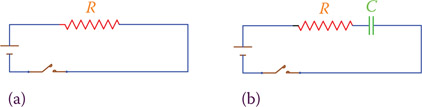
Figure 6.21
Adding a capacitor to a DC circuit. (a) Circuit without capacitor; normal current after switch is closed. (b) Circuit with a capacitor; current only for a short time no current afterwards.
Water flows in the pipeline in Figure 6.22a as the electricity flows in the circuit of Figure 6.21a, as long as the reservoir (battery) is not emptied. Nevertheless, in the case of Figure 6.22b a current of water flows as long as the small tank is not full. That is, for a short period of time, there is a current in the pipeline, but after a while water stops flowing. Moreover, this flow of water is not uniform during the period. In the beginning (when the tank is empty), more water flows but toward the end the flow of water becomes less and less, approaching zero. This is exactly what happens in the electric circuit containing a capacitor, too.

Figure 6.22
Adding a small tank to the end of a pipeline. (a) Hydraulic system analogous to Figure 6.21a. (b) Hydraulic system analogous to the DC circuit with a capacitor, in Figure 6.21b.
When a capacitor is inserted inside a DC circuit, for a short period of time after the switch is turned on, current flows in the circuit. In the beginning this current is higher but gradually becomes smaller and smaller until it diminishes. This is when the capacitor has charged, and it does not accept electric charge anymore. At this time and afterward, there is no current flowing in the circuit. Thus, except for a short period in the beginning a capacitor in a DC circuit blocks the circuit and does not allow any current.
A charged capacitor contains electricity and behaves like live electricity. It can be dangerous if the voltage is sufficiently high. The voltage level to which a capacitor charges is the same as that of the battery (power supply) if the capacitor becomes fully charged. If the circuit is broken (the switch is turned off) while the capacitor is charging, it only partially charges and to a voltage less than the applied voltage.
A capacitor in a DC circuit blocks the current, except for only a short period following a change such as after a switch is closed (or opened if already closed).
It is interesting to know how long it takes for a capacitor to charge. In fact, in many timing devices, including electronic watches, this time period is used for time keeping. The time for charging or discharging a capacitor has a direct correspondence with the problem for a water tank to fill (under a given water pressure) or empty if already full (based on the height of water and the resistance of the pipeline from which water discharges).
Here a simple rule is given for the calculation of the time for charging a capacitor. At the end of this chapter we provide additional material on this subject. Referring to Figure 6.21b the circuit consists of a resistor with resistance R and a capacitor with capacitance C in series with each other connected to battery (power supply) of voltage V. We define a time constant τ (the Greek letter corresponding to English t, and pronounced tow).
Time constant: Duration of time for a circuit containing a capacitor or inductor and resistors to reach 63 percent of a new value after a change has happened to the circuit (e.g., its power has been turned on or off).
| τ=RC | (6.10) |
When R is defined in ohm and C in farad, τ is automatically expressed in seconds. As can be seen, the time constant τ depends on the values of R and C. It takes approximately 5 times the time constant τ for the capacitor to fully charge to voltage V. This time starts from the instant that the switch is closed. But, if during this time interval the switch is opened, the capacitor does not fully charge. The time constant is sometimes shown by T (uppercase) instead of τ.
Example 6.21
A 51 Ω resistor and a 10 mF (millifarad) capacitor in series are connected to a 12 V battery. How long does it take for the capacitor to charge?
Solution
The time constant is calculated first:
τ = RC = (51)(10 ÷ 1000) = 0.51 sec
The required time for charging the capacitor = 5τ = (5)(0.51) = 2.55 sec
Example 6.22
How much current is in the circuit of Example 6.21 after 5 sec following closing the switch?
Solution
Current diminishes to zero at the end of the charging time (2.55 sec). Thus, the current at 5 sec after the switch is closed is 0.
Because this time period of charging is relatively very small, it can be ignored compared with longer periods of time i. Thus, in general, we consider a DC circuit to be open when it contains a capacitor.
Except for a very short period in the beginning, a capacitor in a DC circuit behaves as an open circuit and does not allow any current.
It takes approximately 5 times the time constant for a capacitor to either charge or discharge.
6.12 Inductors in DC Circuits
Figure 6.23 illustrates a simple DC circuit consisting of a resistor with which an inductor is added in series. We are interested to see what the effect of this inductor to the circuit is. The effect of an inductor in an electric circuit is always to oppose a change in the circuit current. For instance, at the instant the switch is closed, current tends to increase from zero to a value that depends on the voltage and resistance in the circuit. An inductor wants to keep the current unchanged. Eventually, after a short period of change, the current settles at a value and remains constant for this DC circuit.
Adding an inductor in an electric circuit is analogous to adding a flexible (stretchable) tank (reservoir) to a hydraulic pipeline. When the tank stretches, its volume changes. When the valve in the pipeline is opened to let water flow, the flowing water must fill the flexible reservoir before it can continue its normal flow. Thus, part of the flow is used to fill the reservoir. Once the reservoir is filled, water flow continues in the pipeline at its normal rate. In other words, the flow of water is initially resisted and limited for a short period of time but afterward will have a continuous and constant current.
The effect of an inductor in an electric circuit is to oppose a change in the circuit current (keeping the current unchanged).
Here again it is interesting to know how long it takes for the electric current in Figure 6.23b to reach its constant value or for the water in Figure 6.24b to reach its normal flow. Associated with the circuit resistance R and inductance L values, we may define a time constant (similar to the case for a capacitor) as follows:
| τ=LR | (6.11) |
When L is defined in henries and R in ohms, τ will be in seconds. This equation implies that for smaller values of R the duration of the effect of inductor is longer. It takes approximately 5 times the time constant for the current to reach its constant value.

Figure 6.23
Adding an inductor in series with a resistor in a DC circuit. (a) Original circuit. (b) Circuit with an inductor.
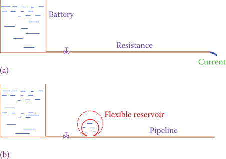
Figure 6.24
Analogy of a hydraulic system to an electric circuit when an inductor is added. (a) Circuit without an inductor. (b) Circuit with an inductor.
Example 6.23
What is the time constant in a circuit containing a resistor and a coil in series? The resistor has a value of 51 Ω, and the coil has an inductance of 11 mH and a resistance of 4 Ω.
Example 6.24
What is the final current in the circuit of Example 6.23 if the battery voltage is 6 V? And how long after the switch is closed does the current reach this final value?
Solution
The final current is established after the effect of the inductor on current ends. The final current is found from Ohm’s law. The total resistance of the circuit is 51 + 4 = 55 Ω, and on the basis of Ohm’s law,
| I=VR=655=0.109 A = 109 mA |
It takes approximately 5 times the time constant before the current reaches this value; thus, the current reaches 109 mA after
(5)(0.2) = 1 msec
It takes approximately 5 times the time constant for the effect of an inductor in a DC electric circuit to disappear.
Time Constant in DC Circuits
Capacitor
A capacitor has a storage capability for electricity. When it is part of a DC circuit, it exhibits an apparent opposition to a change in the circuit voltage. When a switch turns on or off the power to an electric circuit, it introduces a change of voltage to the circuit. During turning the power on in a DC circuit containing a capacitor, first, the capacitor is charged. Similarly, at power off, first, a capacitor in the circuit releases its charge to the circuit. Consequently, a delay is associated with both turning on and turning off a DC circuit. As a result of this delay, it takes a short while before the circuit containing a capacitor reaches its equilibrium and comes to its final condition when a change in voltage, either increasing or decreasing, occurs. This delay depends on the capacitance of the capacitor and the resistances in the circuit.
The delay just mentioned is approximately 5 times the time constant of the circuit.
The time constant for a circuit containing capacitors with an equivalent capacitance C and resistors with an equivalent resistance R is
Time constant = RC
When R is in ohm and C is in Farad, the time constant is determined in second.
The figure below shows the two cases of increasing and decreasing the voltage in a DC circuit. Because this change in voltage can be any value, it is normalized and its magnitude is shown as 1, which percentagewise represents 100 percent. The figure illustrates the gradual change of voltage during the time it takes for this change. The time constant is depicted as T, and the percentage change after the elapse of each time constant T is also shown.
For an increase in voltage (like turning on a switch), part (a) in the figure illustrates that subsequent to the initiation of an increase in voltage, after T seconds the voltage increases by 63 percent of difference between the new and the old values. In the figure, the old value is zero, but it can be a nonzero value. After 2T sec the voltage is augmented to 86 percent of the change. After 5T, 99 percent of the change is reached, which is almost the total change to occur.
Part (b) of the figure illustrates a decrease in voltage. If the change is caused by turning the power off, so that the final voltage is zero, 63 percent of decrease in voltage takes place after one time constant. That is, the circuit voltage drops to 37 percent of its initial value. Accordingly, after 2T the voltage drops to 14 percent and after 5T the decrease is 99 percent and the voltage in the circuit is 1 percent of its initial magnitude. After this time the voltage change is practically zero.

The delay introduced by a capacitor has many applications, particularly in electronic circuits used in radio, TV, communications, and so on, as well as in electrical applications that need control and regulation. By changing the time constant, through R and C, a desired delay can be obtained for any application.
Inductor
In the same way that a capacitor causes a delay for the voltage change in a circuit, because of its intrinsic electricity storage property, an inductor in a circuit causes a delay. However, the delay caused by an inductor is because of the property of an inductor to resists a change in the current in the circuit it is a part.
The time constant for a circuit containing an inductor and a resistor is defined by
| Time constant = LR |
When L is henries and R is in ohms the calculated value of time constant is in seconds.
All what was said about the time delay for changing voltage in a circuit containing capacitors and resistors and the corresponding graphs is true for a circuit having inductor in it. However, in this case, the values and the percentage of change shown at the end of periods T, 2T, 3T, etc., corresponds to changes of current in a circuit and not voltage.
6.13 Power in DC Circuits
In the previous two sections, we studied the effect of a capacitor and an inductor in a DC circuit. On the basis of this study we know that this effect is only for a short period of time after a switch is turned on or off. Turning a switch on and off is, in fact, a change of power to a circuit. In many electric circuits when a switch is turned on, no other condition changes for a relatively long time. However, in electronic circuits many factors can change with time and new conditions are introduced repeatedly and on a continuous basis. For example, in a radio circuit the signals (voltages created by a microphone) corresponding to someone’s talking, or music, continuously vary.
In this respect, the time scale of electric circuits and electronic circuits are completely different. Without loss of generality we can assume that for DC electric circuits we deal only with resistors (or resistive components), because the existence of a capacitor introduces an open in a circuit, and an inductor only adds its resistance to a circuit. The matter is different for AC circuits, which we will discuss in Chapter 8. Moreover, electronic circuits are dealt with later in Chapters 13 to 20. As a result, from now on when we refer to a DC electric circuit it is assumed that we have only resistive elements in the circuit (no capacitor and no inductor).
In this section we consider the power associated with a DC circuit. As noted before, the resistors are the consumers of power and the electric power supply is the provider of that power. A circuit can be a series circuit, a parallel circuit, and a series-parallel combination circuit. In all these cases the total power consumption by the circuit is the sum of all the individual power consumption of all the resistors in the circuit. To find power consumption for a circuit, thus, we may (a) find and add together all the individual powers, (b) find the power in the equivalent resistor of the circuit, or (c) find the power consumption in various parts of the circuit. The following example illustrates the matter.
Example 6.25
The circuit shown below is the same circuit as shown in Figure 6.14. It is illustrated this way for your convenience (the physical circuit could have been not so straightforward). Values of resistors are shown in the figure. We want to find the total power (consumption) of this circuit. Pay attention to the numbering of the resistors. This way, the same number subscripts are used for the currents and the resistors; that is, the current in R1 is I1 and so on, except for R6 (whose current is the total current in the circuit). See Figure 6.25.
Solution
To find the individual power consumptions, the current for each resistor should be known. Also, for calculation of the power using the total current, the equivalent resistance of the whole circuit is required. Although the second way needs less calculation, here we are going to find the power in both ways as a demonstration that the two values are equal.

Figure 6.25
Circuit and values for Example 6.25.
There are two sets of parallel resistors in this circuit, which when substituted by their equivalent resistors, respectively, the whole circuit reduces to three resistors in series. For ease of reference, we numerate each step as we proceed:
- Find the equivalent values of each parallel set of resistors:
Equivalent resistance of R1 and R2=R12=(200)(300)500=120 Ω Equivalent resistance of R4 and R5=R45=(400)(600)1000=240 Ω Equivalent resistance of R3 and R45=R345=(240)(240)480=120 Ω -
Find the equivalent resistance of series resistors R6 + R12 + R345:
RTotal = R6 + R12 + R345 = 60 + 120 + 120 = 300 Ω
At this point we may use the rule of a voltage divider to determine the voltages across different points as follows:
Voltage between points L and M = VLM=24 × 60300=4.8 V - Find the total current:
- Find the currents in R1 and R2:
- Find the currents in R3, R4, and R5:
- Verify the currents in R1 to R6:
- I1 + I2 = 48 + 32 = 80 mA
- I3 + I4 + I5 = 40 + 24 + 16 = 80 mA
- Find the sum of the powers in all resistors:
- Find the power from equivalent resistance:
P = (300)(0.08)2 = 1.920 W
- Also, you may want to verify the following:
(4.8)(0.08) + (9.6)(0.08) + (9.6)(0.08) = 0.384 + 0.768 + 0.768 = 1.92 W (using P = VI)
6.14 Chapter Summary
- In a series circuit all components are connected one after another, so that they form a single loop.
- In a series circuit the current is the same for all components in series with each other.
- In a series circuit, applied voltage divides between the components. The component with larger resistance has a larger voltage across it.
- In a parallel circuit the same voltage is applied to all components in parallel. Each component has a direct connection to the supply voltage.
- In a parallel circuit there are as many currents as there are circuit branches.
- In a parallel circuit, total current is obtained by adding all the individual currents (the currents in all branches). This is the current through the power supply, and the power supply must be able (have enough power) to provide this current.
- In a parallel circuit the component with the largest resistance has the least current.
- In either a series circuit or a parallel circuit composed of resistors, one can find one single resistor to replace all the resistors. This resistor is called the equivalent resistor.
- In a series circuit the equivalent resistor is larger than all the resistors. In a parallel circuit the equivalent resistor is smaller than all the resistors.
- A combined circuit has both series and parallel parts.
- A combined circuit consisting of resistors can be represented only by one single equivalent resistor.
- All the rules of series and parallel circuits apply to series parts and parallel parts of a combined circuit, respectively.
- A voltage divider is an arrangement that allows various voltages from a single power source with one single voltage. Various voltages obtained by a voltage divider are always smaller than the power supply voltage.
- A capacitor in a DC circuit acts as an open circuit and does block the current.
- An inductor in a DC circuit adds its resistance to the circuit.
- Associated with a capacitor (or an inductor) in an electric circuit, there is a time constant that depends on the circuit resistance and the capacitor capacitance (inductor inductance).
- For only a very short period of time a capacitor or an inductor in a DC circuit affects the current in the circuit. This period is approximately 5 times the time constant.
- Power in any DC circuit can be found from the total current and the equivalent circuit or from adding the individual powers of all the resistors.
Review Questions
- What is a series circuit? How many loops does a series circuit have?
- What is the equivalent resistor for a set of series resistors? Is it larger or smaller than the largest resistor? Is it larger or smaller than the smallest resistor?
- In series resistors, how many switches do you need to turn off the power from all the resistors?
- How do you define parallel circuits?
- Are the four elements on the top of an electric oven in series or in parallel?
- How do you determine the equivalent resistor in parallel resistors?
- What is the relationship for voltages in parallel resistors?
- What is the relationship for currents in parallel resistors?
- What is meant by combined series and parallel circuit?
- Can you substitute a set of resistors combined together in series and parallel by a single resistor?
- What is a voltage divider used for?
- Can one obtain any desired voltage from a voltage divider?
- Can you get 12 V from a voltage divider if the power supply is 9 V?
- Which way is better to find power in a DC circuit, adding all the individual powers or using the equivalent circuit and its current?
- In a DC circuit, is the power consumption of all the loads larger or the power to be delivered by the power supply? If so, why?
- Does a capacitor conduct electricity when in a DC circuit?
- Does an inductor conduct electricity when in a DC circuit?
- What is “time constant” in a DC electric circuit? Does it mean that the time is constant?
- When dealing with an electric circuit, when/what does normally define the start of time?
Problems
- A lightbulb is connected to 120 V electricity through a switch, using three pieces of wire (one between the + and the switch, one between the switch and the lightbulb and one between the lightbulb and the −) of the required lengths. If the resistance of the lightbulb filament is 70 Ω, the resistance of each shorter wire is 0.5 Ω and the resistance of the wire between the light and the switch is 1 Ω, draw a schematic of the circuit. What is the total resistance in the circuit?
- What is the current in the circuit of Problem 1?
- In Problem 1, what is the power that the source must supply?
- In Problem 1, how much of the power provided by the power supply is used in the filament of the lightbulb?
- Where does the rest of the power provided by the power supply go?
- What is the equivalent resistance of the circuit in Figure P6.1?
- If the current in the circuit of Figure P6.2 is 12 mA, what is the resistance R2?
- In the following circuit (Figure P6.3), what is the voltage across R3?

Figure P6.2 Circuit of Problem 7.

Figure P6.3 Circuit of Problem 8.

Figure P6.1 Circuit of Problem 6.
- In the circuit of Problem 8, find the value of R3.
- What is the total power used in the circuit of Figure P6.3?
- Find the total current in the circuit of Figure P6.4.
- Explain why the circuit in Figure P6.5 is a parallel circuit.
- Find the current in the circuit shown in Figure P6.5.
- Find the equivalent resistance of the circuit shown in Figure P6.6.
- Find the current in each of the 51 Ω resistors in the circuit of Problem 14.
- In the circuit of Figure P6.6 determine, without calculation, if the current in the left 100 Ω resistor is higher or lower than that on the right?
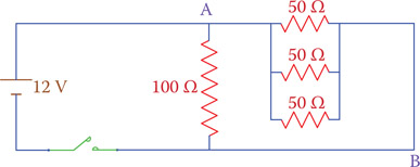
Figure P6.5 Circuit of Problems 12 and 13.

Figure P6.6 Circuit of Problem 14.
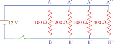
Figure P6.4 Circuit of Problem 11.
- Find the equivalent resistor of the circuit shown in Figure P6.7.
- Find the power consumption of the circuit of Figure P6.7.
- In the circuit of Figure P6.8, if all the resistors have similar power capacity, what is wrong with the design of this circuit?
- How much is the total power consumption of the circuit in Figure P6.8?
- Using the conversion tables in Chapter 2, determine how many calories are generated in 1 sec in the circuit of Problem 20.
- Determine how many calories are generated in the circuit of Problem 20 within 24 hr.
- In the circuit shown in Figure P6.9 the coil has 10 Ω resistance. What is the time constant of the R-L circuit?

Figure P6.7 Circuit of Problem 17.
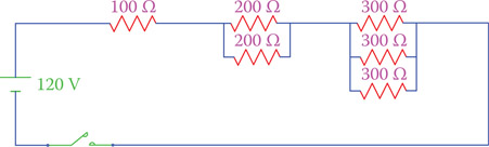
Figure P6.8 Circuit of Problem 19.
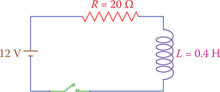
Figure P6.9 Circuit of Problem 23.

Figure P6.11 Circuit of Problem 26.
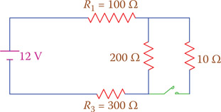
Figure P6.10 Circuit of Problem 25.
- What current is in the circuit of Figure P6.9 after the effect of the coil ends?
- In the circuit shown in Figure P6.10, find the power to be provided by the battery (a) when the switch is open and (b) when the switch is closed.
- In the circuit shown in Figure P6.11, find the power consumed in the resistor marked by an arrow.