
11
AC Motors and Generators
OBJECTIVES: After studying this chapter, you will be able to
- Describe the way most AC motors work
- Explain the difference between various AC motors
- Define what a rotating magnetic field is
- Recognize the difference between an AC motor and a DC motor
- Understand that AC motors and AC generators have the same structure
- Explain synchronous speed of an AC machine and understand various standard synchronous speeds
- Associate synchronous speeds with frequency
- Formulate power and other relationships for AC motors
- Understand the difference between single- and three-phase motors
- Calculate current for motors in order to select fuses
- Understand and apply relationships for power correction to motors
- Judge if a motor and a generator are compatible
New terms: Alternator, asynchronous machine, breakdown torque, capacitor-run motor, copper loss, core loss, dynamic braking, full load torque, locked rotor current (LRC), locked rotor torque (LRT), pull-out torque, pull-up torque, reluctance, reluctance force, rotating magnetic field, rotor, shaded pole, slip, slip speed, split-phase motor, squirrel cage machine, stator, stray loss, synchronous motor, synchronous speed, universal motor, windage, wound rotor induction machine (WRIM)
11.1 Introduction
In Chapter 7 we discussed DC motors and DC generators. We discussed how a DC machine works and that DC motors and generators have the same structure, and we can simply call them DC machines. Moreover, we discussed how motors and generators work based on Lorentz force and Faraday’s law, which could be interpreted as the interaction between an electric field and a magnetic field that could be created by a winding or a permanent magnet.
The way an AC machine works, in general, is not exactly the same way DC machines work, although, again, the structure of an AC motor and an AC generator is the same. The latter statement implies that if an AC machine is rotated by a prime mover (mechanical energy is given to it), it generates electricity (generator), and if it is provided with electrical power, it delivers mechanical power (motor). Despite this similarity, a machine can be made for one purpose only, either as a motor or as a generator. One could say, in general, that AC machines work based on the interaction between two magnetic fields. One of them can be a permanent magnet in some machines.
In this chapter we learn the principal aspects of AC motors and generators (AC machines). Because understanding of the subject is easier with three-phase motors, we start with three-phase machines.
11.2 Main Categories of AC Machines
AC machines (generators and motors) initially fall into single phase (denoted also by 1 ϕ or one phase) and three-phase motor (3 ϕ). In each of these categories, then, we have synchronous and asynchronous (also called induction) machines. Induction machines are of two types, wound rotor and squirrel cage. There is, moreover, another type of motor that is called a universal motor. A universal motor is a single-phase motor (no three-phase counterpart) that works with both AC and DC; thus, it’s called universal. A universal motor is, in fact, a series wound DC motor. We will see how, in accord with the principle based on which it functions, it can use AC electricity as well as DC.
Universal motor: Type of motor that can work with both AC and DC. A series-wound DC motor has this capability.
There are other types of motors that are either very specific in the way they work or are used for very specific applications. Just to name a few, there are linear motors, which have a linear motion, rather than rotational motion, ultrasonic motors that are very small in size and capacity, hysteresis motors, step motors, and brushless DC motors (which is, indeed, an AC motor with a DC-powered driver). Except for the linear motors, which can be used for traction of railed vehicles, the others are normally small (fraction of a horsepower). Also, the term machine cannot be applied to these motors because they cannot work as generators or even if they do, nobody uses them as generators.
Before one can learn about how an AC motor works, it is necessary to understand the concept of rotating magnetic field. All three-phase motors work based on a rotating magnetic field; that is, a magnetic field that, though not visible, has a rotational motion.
Rotating magnetic field: Magnetic field with constant strength but rotating about an axis, formed in the stator of three-phase machines when connected to electricity. Such a rotating filed is developed because the three windings are physically apart by 120°.
11.3 Rotating Magnetic Field
Referring to electromagnets (see Section 7.3.2) if a coil is connected to a DC source a magnetic field is generated in the coil, the direction of which is found according to Figures 7.6 and 7.7. Consider now if the source is AC with a frequency of 50 Hz. Again, a magnetic field is generated, but this time its north and south pole swap places rapidly with the change in the current direction (100 times per second).
Now, consider three pairs of similar but separate windings that are connected to the three phases of a three-phase supply, each pair connected to one phase. Because the voltages in the three phases are not in phase with each other, the magnetic fields, accordingly, are not reaching their maximum and minimum strength at the same instants. Figure 11.1 shows these windings that are physically placed 120° from each other. Because three-phase voltage has a sinusoidal pattern, the strength of each magnetic field traces a sinusoidal pattern, which continuously varies from zero to a maximum and back to zero, and then changing direction, repeating the same pattern in the opposite direction. We may schematically show the resulting magnetic field by two opposite vectors that depict the direction and only the maximum and minimum lengths, corresponding to the peak values. As said before, because voltages in a three-phase system are 120° out of phase, the variations of the three fields are not coincident, and their maximum and minimum values do not occur at the same time.

Figure 11.1
Three windings connected to three voltages of a three-phase system.
Figure 11.2 illustrates the direction of the magnetic field for the maximum positive and the maximum negative values of the current in phase A, the maximum currents for phased B and C, and for some negative current in phase B.
At each instant of time the resulting magnetic field is obtained by adding together the three individual magnetic fields developed in the three windings. For this addition, however, as well as the magnitude, direction of the magnetic fields must be brought into account because the windings are at 120° from each other. In other words, addition implies the vector sum of the three magnetic fields. Because the magnetic fields are not constant, at each instant of time the resultant magnetic field has a different direction within 360°. Some of these positions are shown in Figure 11.3. It can be graphically and mathematically shown that the resultant has the same magnitude, but its direction continuously changes. In fact, it can be seen that the resulting magnetic field rotates with time. Speed of rotation is constant and for the arrangement in Figure 11.1 (one pair of windings for each phase) is the frequency of the AC line. That is, if the line frequency is 50 Hz, the speed of the rotating magnetic field is 50 revolutions per second. For three winding pairs, as was the case in Figure 11.1, for each one cycle of current, the resulting magnetic field rotates by one revolution. The same arrangement can be practiced with two sets of windings (six pairs) connected to three phases in a correct order and each one being physically at 60° from the neighboring windings (instead of 120°). In such a case, it can be seen that for each full cycle of current variation the magnetic field revolves half a revolution.

Figure 11.2
Direction and magnitudes of magnetic fields of windings in Figure 11.1 at a number of times.

Figure 11.3
Illustration of three positions of the rotating magnetic field.
By increasing the number of windings and connecting them in a proper manner, the number of revolutions per second of the magnetic field can be modified. This is what is done in AC machines to change the operating rpm. The relationship between the number of poles (each pair of windings counts for one set of north and south poles) and the rotating speed is
| (11.1) |
In this equation, NS is the rotational speed in revolutions per minute (rpm), f is the line frequency in Hertz, and p is the number of pairs of poles per phase. That is, for six windings as shown in Figure 11.1, for instance, p is equal to 1. The subscript S in NS represents the synchronous speed For any AC machine, synchronous speed is determined by the frequency of the line it is connected to because the number of poles is a physical constant when the machine is built. In some machines the arrangement of poles can be modified; in such a case a machine can have two speeds (one twice the other). This is done outside the machine by a special switch.
Synchronous speed: Special speed for an AC machine depending on its number of poles and the frequency of the AC line.
In three-phase machines a rotating magnetic field is developed by the stator windings.
For lower-speed machines (higher number of poles) poles are distinct, but for a lower number of poles windings are distributed around the periphery of a cylindrical support (Figure 11.4). The set of windings forming the magnetic poles is called the stator. These windings do not rotate but create the rotating magnetic field. Figure 11.4 shows the stator winding of a three-phase generator. The generated magnetic field has its strongest effect in the cylindrical space inside the winding, where the rotor is inserted, and its axis of rotation coincides with the stator axis.
Stator: Stationary part of AC electric machines, as opposed to the rotor that rotates.
Direction of rotation of the magnetic field depends on the order the windings are connected to a three-phase circuit. If (any) two connections are interchanged, the direction of rotation of the magnetic field reverses.
Rotor: The rotating parts of any motor, generator, turbine, and so on. In a propeller-type turbine, the motor consists of the hub and the blades.
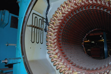
Figure 11.4
Stator windings of a three-phase generator. (From Hemami, A., Wind Turbine Technology, 1E ©2012 Delmar Learning, a part of Cengage Learning Inc. Reproduced with permission from http://www.cengage.com/permissions.)
The rotating part of an AC machine is called a rotor. It has a cylindrical form and is supported by bearings; it resides inside the stator and has a very small clearance from the inner diameter of the stator windings. Remember that in DC machines two different terms are normally used instead of stator and rotor. Figure 11.5 illustrates a cutaway of a three-phase machine; notably, it shows the rotor that sits inside the rotating magnetic field. This machine is much smaller than that in Figure 11.4, and all the inside components are on the same frame, whereas for large machines each component is separately supported. Most small machines have fins at one end of the rotor structure, which function as a blower when rotating, forcing air across the hot components (mainly the stator windings) in order to carry the heat away. This is also shown in Figure 11.5.

Figure 11.5
Cutaway of a three-phase motor. (Courtesy of ABB Inc.)
If (any) two connections of a three-phase system to the stator of an AC machine are interchanged, direction of rotation of the rotating magnetic field reverses.
In order for AC machines to work, the stator must be connected to electricity. Unlike DC machines, it is not necessary to also connect the rotor to electricity. When this connection is made, a rotating magnetic field is created inside the body of the stator. It is like a rotating magnet that can pull and move ferrous metals with it.
The stationary part of an AC machine is called the stator.
Example 11.1
The stator of a three-phase AC machine has a total of 24 poles. What is the rotating speed of the magnetic field developed in this machine when it is connected to 60 Hz line?
Solution
Because the machine is three-phase, the number of poles per phase is 8. Because poles have to be in pairs of north and south, then there are four pairs of poles; thus, p = 4. Using p = 4 and f = 60 in Equation 11.1 gives
Table 11.1 Synchronous Speed for Various Number of Poles

11.4 Synchronous Machines
A synchronous machine has a rotating magnetic field, as described in Section 11.3, in its stator when connected to a line of the compatible voltage and a magnet in the rotor. If the magnet in the rotor is rotated by mechanical means, we have a generator, otherwise, a motor. A synchronous machine is characterized by its synchronous speed, as defined by Equation 11.1. Because the common operating frequencies in the world are 50 and 60 Hz, the synchronous speeds can be uniquely defined for the number of poles of a machine.
Note that in Equation 11.1, p is the number of pairs of pole per phase. Alternatively, this formula can be written as
| (11.2) |
where P is the total number of poles in the stator (P = 6p). Table 11.1 shows the synchronous speeds for 50 and 60 Hz for common synchronous machines.
11.4.1 Synchronous Motors
Synchronous motors always have a constant speed that is determined by the relationship in Equations 11.1 or 11.2. This is a desired requirement for certain loads that no matter how much the load varies (the torque and power requirements), speed must be constant. Moreover, the synchronous motor has another property that is desirable. It can be run at any power factor. Thus, if alone, it can be run at pf = 1, or if run in a circuit that has many other types of motors it can run at a leading power factor to compensate for the lagging power factor of the other motors (other AC motors have a lagging power factor). In this sense, while running, it can induce a capacitive effect in the circuit to which it is connected.
Synchronous motor: Type of AC motor (usually very large size) that is insensitive to load change and always runs at a fixed (synchronous) speed, unless the load becomes larger than the motor capacity (when it stops working).
A synchronous motor is not self-starting.
Despite the desirable properties of a synchronous motor, it is only used when the requirement justifies for the extra cost of a synchronous motor. A synchronous motor is much more expensive than other type of motor of equal power, and for this reason it is made only in large sizes. The main reason for the high cost of a synchronous motor is its inability to self-start. That is, a synchronous motor is not self-starting. This means that it needs to be started by some additional means. The reason a synchronous motor is not self-starting is because of how it functions.
Figure 11.6 shows how a synchronous motor works. Suppose that there is a rotating magnetic field inside the stator of a three-phase machine. This is like having a large magnet that is rotating. Furthermore, assume that you could manage to put a magnet inside the stator, its axis coincided with that of the magnetic field. Because the magnetic field has a rather high rotational speed, the magnet stays stationary. If the magnetic field was not rotating, the magnet would orient itself aligned with it.
Now, if the above magnet is initially helped to rotate so that it reaches a speed around that of the magnetic field, then it will snatch the magnetic field and latch to it, hence, continuing to rotate with the magnetic field. If the external auxiliary mover is disconnected now, the magnet continues to rotate with and at the same speed as the magnetic field, getting its power from the magnetic field.
The above description clearly indicates that for a synchronous motor to work it is necessary first to rotate the rotor and bring its speed up to near the synchronous speed. Then, after this is done, the motor continues to run without the need of the external starter. For larger machines the starter can be a pneumatic or another electric motor that can move the unloaded synchronous motor and bring its speed up to within a few percent of the synchronous speed. In the smaller motors, this can be another type of AC motor, sometimes embedded in the same frame. A special switch will disengage this auxiliary motor after latching to the synchronous speed has taken place.

Figure 11.6
Principle of operation of synchronous motor.
It also follows from the preceding discussion that a synchronous machine works based on the interaction between two magnetic fields (the rotating magnetic field developed by the current through the windings and that of the magnet). Although the description of how a synchronous motor works suggests that the rotor of a synchronous motor must be a magnet, it is possible to interchange the rotor and stator roles and have a stationary magnet at the stator. In the larger machines, normally, the rotor is a magnet; otherwise, large currents have to be passed through the brushes and slip rings. It can be a permanent magnet or it can be an electromagnet that is powered by a DC source. For very large motors (and generators) the DC source can be a DC generator embedded within the structure of the synchronous machine (sharing the same shaft), which is solely used for magnetizing the rotor. Furthermore, instead of a commutator for the DC generator, an electronic converter can be used, as discussed later on in Chapter 20. For those machines with the magnet rotor, only the stator is connected to the power line. In smaller motors the stator can be a permanent magnet and the rotor is connected to the outside line through three slip rings.
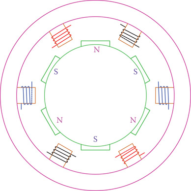
Figure 11.7
The rotor magnet is uniformly distributed around the rotor.
The magnet in the rotor of a synchronous machine is not a single magnet (one pair of north and south poles). To have more uniformity of motion and torque, the rotor consists of a number of magnets uniformly placed around the rotor, as schematically shown in Figure 11.7, based on the stator number of poles.
The rotor in synchronous AC machines is not connected to electricity.
11.4.2 Synchronous Generator
Alternator: Generator of alternating current (a machine that produces alternating current electricity when turned).
A three-phase synchronous generator is the standard type for conventional power generation at a commercial level. Except in wind turbines, or in very isolated cases, power plants employ a synchronous generator, generally called an alternator. A synchronous generator has exactly the same structure as a synchronous motor. Because generators are usually very large (up to 1 GW for some nuclear power plants), the rotor is the magnet that rotates. In this way, slip rings are avoided (slip rings need regular maintenance because of the wear of the brushes and sparking under high currents). As the magnetic field of the rotor cuts the wires of the three sets of windings in the stator, three-phase electricity is developed in the stator windings. The rotor, again consisting of a set of magnets as shown in Figure 11.7, must be rotated by a prime mover at precisely the machine synchronous speed (depending on the machine’s number of poles) to generate electricity at a desired frequency.
The formulae for synchronous speed still apply, but this time the frequency is a function of the rotating speed. Thus, if a machine with a total of P poles is rotated at N rpm, the frequency of the generated electricity is
| (11.3) |
So, for example, if a machine with a total number of 18 poles is rotated at 1800 rpm, the frequency of the generated electricity is 90 Hz, and if rotated at 900 rpm, the frequency is 45 Hz. To generate electricity at standard frequencies of 50 and 60 Hz, thus, the generator must be rotated only at synchronous speeds listed in Table 11.1. For P = 18 this speed is 1000 rpm for 50 Hz and 1200 rpm for 60 Hz.
Table 11.1 illustrates that for a given frequency the lower the number of poles, the faster the generator must be turned. In this respect, generators that are energized by steam and gas turbines have a smaller number of poles compared to those powered by hydraulic turbines because steam and gas turbines run at a higher speed than hydraulic turbines. For instance, in a water turbine driven generator the total number of poles can be 96 (P = 96); that is, 16 pairs per phase (p = 16). In order for the electricity to have a frequency of 60 Hz, the turbine must run at 225 rpm.
The number of poles in a generator determines its structure and diameter size owing to the fact that all the poles must be accommodated around the periphery of the generator stator. Accommodating more poles requires a larger diameter. For the same power capacity, generators with fewer poles are slimmer and longer, and those with more poles are larger in diameter but shorter in length.
When frequency is not important (e.g., for heating elements or when the generated power is to be converted to DC), it is thus possible to run a generator at any speed. For instance, in a certain mode of operation of wind turbines a synchronous generator produces electricity at a frequency determined by the wind speed, but this is converted to DC before it is converted back to AC with the desired frequency.
11.4.3 Characteristic Curves of Synchronous Machines
In many synchronous machines, in particular the larger ones, the rotor magnetic field is not supplied by a permanent magnet; instead, it is created by an electromagnet powered by a DC generator. In this way the strength of the rotor magnetic field can be controlled by varying the DC voltage. This voltage is applied to the rotor winding. Increasing this voltage increases the excitation current through the rotor winding.
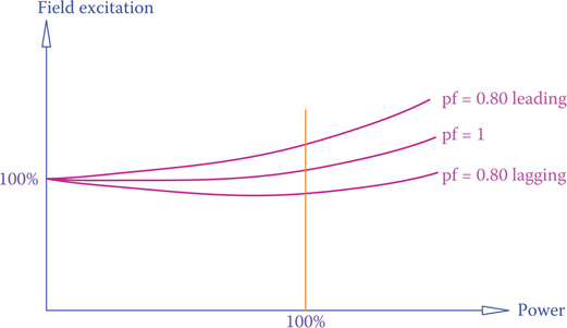
Figure 11.8
Over- and under-excitation of a synchronous machine.
In the majority of applications (no matter a generator or a motor) the stator voltage is constant, but the power demand from a generator or the mechanical power of a motor can vary. For a constant stator voltage as power demand increases, the rotor excitation current must be increased accordingly. This is shown by the middle curve in Figure 11.8. Nevertheless, it is possible to overexcite the rotor by increasing the DC voltage fed to the rotor winding. It is also possible to provide less voltage to (under-excite) the rotor. The effect of field over-excitation in a synchronous machine is to run it (both generators and motors) with a leading power factor and the effect of field under-excitation is to run the machine with a lagging power factor. Typical curves for these conditions are also depicted in Figure 11.8 for pf = 0.8.
As a motor, this property can be used to correct the power factor of a circuit. Specifically, in the cases that there are many motors connected to a circuit because the motors behave like inductors and cause a circuit to lag, if one or more of the larger motors is a synchronous motor it can improve the power factor of the circuit when running. For this purpose the motor(s) must run with a leading power factor (see Section 11.8.5).
11.4.4 Single-Phase Synchronous Machines
Whereas single-phase synchronous generators are very common for small electricity production in fixed or mobile units, they do not have a place in commercial electricity production. The structure of a single-phase alternator can be the same as its three-phase counterpart except that it has only one set of windings instead of three sets. In this sense, Equation 11.1 can also be used for a single-phase generator (but not Equation 11.2).
Alternatively, instead of having the magnet in the rotor and rotating, it can be in the stator and stationary, like in DC machines. In such a case, the rotor has a winding in which electricity is generated and is transferred to outside through slip rings. This is shown in Figure 11.9. Note that the structure of such a machine and how electricity is generated is exactly the same as happens in a DC generator, with the exception of the commutator, which converts the otherwise AC electricity to DC electricity. In Figure 11.9, variation of the generated voltage during one turn of the rotor (for a single pole machine) is illustrated and identified by letters A to E. In this sense, a DC generator and a single-phase alternator can have identical construction with the exception of the commutator versus a pair of slip rings, which helps to distinguish them from each other.

Figure 11.9
Single-phase alternator similar to a DC machine without commutator.
As for single-phase synchronous motors with the structure as explained earlier, they are not built. There are, nevertheless, some single-phase motors (such as reluctance motor) that have a constant speed. Because of this constant speed property, some people categorize them as synchronous motors, whereas they work based on a different principle than was described in this section (see Section 11.7).
11.5 Asynchronous or Induction Machines
Asynchronous machines are more known as induction machines because their principle of operation is based on induction. Recalling Faraday’s law from Chapter 7 (see Section 7.5), if a wire is moved in a magnetic field, then a voltage difference is generated between its two ends. We may also say a voltage or an electromotive force is induced in the wire. Remember, also, that it is the relative motion between a wire and a magnetic field that counts; that is to say, the wire can be stationary while the magnetic field moves.
Asynchronous machine: Another name for induction motor (see induction machines).
This principle, together with the rotating magnetic field, constitutes the basis for operation of induction motors and generators. Hence, one can say the difference between synchronous and induction machines lies in their rotors. In other words, it lies in how the magnetic field in the rotor is made. In this sense, the structure of the stator for a synchronous machine and an induction machine is the same, and only the rotors differ from each other. That is to say, in principle, one can interchange the stators of two similar (in size and power) synchronous and induction machines.
There are two types of induction machines. The difference again comes from the structure of the rotor, and the two types are named based on the rotor structure. One type is called squirrel cage machine and the other is called wound rotor induction machine (WRIM). The rotor of the squirrel cage machine has no winding, and there is no need for the rotor to be electrically connected to any electricity. The rotor of the latter, however, as the name implies, has windings. The windings must be connected to circuits outside of the rotor, though not to the three voltage lines. The arrangement for windings on the rotor, which rotate, to be connected to outside circuitry that is stationary is done through slip rings. Slip rings, as briefly described in Section 7.4, are metallic circular rings mounted and rotating with the rotor shaft and connected to the rotor windings but insulated from the rotor body. Brushes are spring loaded to make good contact with the surface of the rings. They do not rotate and are connected to the outside circuitry. Remember that in DC machines we had brushes and commutators. The difference between slip rings and commutators is that the former is made of one piece of metal, whereas the latter consists of many isolated pieces of metals around a ring. In both cases they are isolated from their shafts. Also, for DC machines, there is only one commutator, but for AC machines there are two (for single phase) or three (for three-phase) rings.
Squirrel cage machine: Type of alternative current induction machine in which the rotor winding has little resistance and thus carries very high current. To withstand high currents, the rotor structure is modified and more resembles a cage than a winding.
Wound rotor induction machine (WRIM): Type of induction machine for AC in which the rotor has wire winding. The windings are accessible through slip rings. Another type is (squirrel) cage machine that has no wire winding and has no slip rings.
11.5.1 Three-Phase Wound Rotor Induction Machine
Consider Figure 11.10 in which a one loop wire (for simplicity) is placed inside a rotating magnetic field.
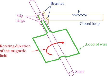
Figure 11.10
One loop of rotor winding connected to outside circuit through slip rings. (From Hemami, A., Wind Turbine Technology, 1E ©2012 Delmar Learning, a part of Cengage Learning Inc. Reproduced with permission from http://www.cengage.com/permissions.)
Notice that the single wire loop is connected to a resistor and together they form a closed loop. Also, notice that the resistor is external to the wire loop and its connection to the wire loop is through slip rings that are mounted on the shaft holding the loop. The loop ends are fixed to the slip rings, and two brushes make the connection between the slip rings and the external circuit.
Rotation of the stator magnetic field is equivalent to moving the wire in a stationary field. The following lines describe what happens as a result:
- Because the magnetic field is moving, it induces a voltage in the wire.
- Because the wire ends are connected to the resistor and form a closed circuit, a current is developed in the loop (including the resistor), proportional to the induced voltage.
- Because of the current in the loop, a force is generated that pushes each side of the loop wire in opposite directions, thus creating a torque. This torque makes the wire loop and its shaft rotate.
- This is what happens in a wound rotor AC induction motor. There is no connection to the electricity for the rotor winding (the loop wire), but the rotor windings make a closed circuit through the external resistor.
- We see that the torque develops if there is a current in the rotor windings. If there is no current, the torque diminishes. In other words, as long as there is a current in the rotor winding, motion exists. This current exists when there is a relative motion between the magnetic field and the rotor winding. If the rotor runs at the same speed as the magnetic field, then there is no relative motion. For this reason, to maintain current, in a motor the rotor always runs slower than the magnetic field.
- For simplicity and clarity, in Figure 11.10 and the above description, there was only one loop. Other loops at different angles can be connected in parallel with the loop shown, using the same slip rings.
- One loop, or a few loops in parallel with each other (two connections), corresponds to a single-phase machine. But, the discussion is equally valid for three-phase machines, having three separate loops (or three sets of parallel loops). The winding in the rotor of a single-phase machine has two terminals that must be connected to the outside of the rotor through two slip-ring-brush sets. Three-phase rotor windings have three terminals and need three slip rings.
The current flowing in the rotor winding cannot be direct current; thus, it has an AC nature (see Section 7.6 for DC machines) at a certain frequency.
The outside resistor can be used for various purposes (e.g., control of the current in the rotor winding when necessary). It can also modify the performance characteristic of a machine, as described in Section 11.5.2.
Normally, winding rotors is a costly job and the slip-rings-brush sets add to the cost and need repairs. For these reasons, the wound rotor induction machines are relatively costly. Their counterpart squirrel cage machines are much cheaper and economically preferred.
11.5.2 Squirrel Cage Induction Machine
Referring to Figure 11.10, suppose that the outside resistor is replaced by a piece of wire with no resistance. This immediately causes a significant increase in the current in the rotor windings. To compensate for the higher current, thickness of the wires in the rotor windings must accordingly be increased. In addition to the wire thickness increase, we observe that in such a case, then, there is no need for a set of slip rings because the external resistors do not exist anymore and, thus, the wire loops can be closed inside the rotor rather than outside the rotor. This latter reality has been the basis of the squirrel cage machines, in which the extra cost of the slip rings and brushes have been eliminated.
The windings of a squirrel cage machine are a number of thick bars of copper, brass, or aluminum (to carry very high currents) that are shorted together (forming parallel components) at both ends. Because the metal bars are connected to two circular rings at their ends, connecting them together, they form a cage shape, as shown in Figure 11.11. The name “squirrel cage,” thus, stems from the shape of the conducting bars.
This is the simplest form of a cage, where the bars have circular cross section; they are parallel to each other and parallel to the rotor shaft. The bars can be slanted (like a twisted cage) or they can have a different cross section rather than being circular. These are variations of models of squirrel cage machines for various reasons or purposes. The aluminum or copper cage is embedded in a ferrous material to increase the permeability of the rotor winding. The ferrous medium is laminated (like the metals in a transformer) to prevent or reduce eddy currents, thus reducing heat and losses. The cage, therefore, is not hollow. A hollow rotor would have a much less efficient performance. The picture of a tiny squirrel cage motor, illustrating the squirrel cage rotor, is shown in Figure 11.12a. (This motor is one phase, since it is so small.) A three-phase 1.5 hp squirrel motor is illustrated in Figure 11.12b.

Figure 11.11
Cage structure of squirrel cage induction machine. (From Hemami, A., Wind Turbine Technology, 1E ©2012 Delmar Learning, a part of Cengage Learning Inc. Reproduced with permission from http://www.cengage.com/permissions.)
Most of the motors used in industry are induction motors. Out of those the majority are of the squirrel cage type. This is because of the obvious economic reason; as was mentioned earlier, beyond the initial higher cost, the wound rotor induction machines need maintenance work on their brush and slip rings, whereas the squirrel cage machine is relatively maintenance free. Hence, unless necessary for any technical reason, after a squirrel cage motor has acceptable performance, it will be the candidate for a job.
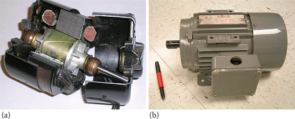
Figure 11.12
Squirrel cage induction machine: (a) very small single-phase motor and (b) 1.5 hp three-phase motor.
As a generator, one can say that almost the only application of induction generators is in wind turbines. The intrinsic performance of this machine matches well with the nature of wind, having a variable speed and not being in our control. Formerly, almost all of the wind turbine generators were of squirrel cage type, but, gradually more and more wound rotor induction generators are being used because of their advantages in grasping more power from the wind, despite their extra cost. Their advantages outweigh the higher cost (learn more about this in Chapter 21).
11.5.3 Characteristics of Three-Phase Induction Machine
Similar to other types of electric machines, a three-phase induction machine can work as a generator and as a motor. For this machine, however, because the stator must be connected to the three-phase circuit, the difference between being a motor or functioning as a generator lies in the speed of the rotor. In general, if the rotor speed is higher than the synchronous speed, then it behaves as a generator, and if the rotor speed is less than the synchronous speed, it becomes a motor. The synchronous speed is determined by the line frequency and the number of poles of the stator winding. The developed rotating magnetic field, after the stator is electrically connected, revolves at the synchronous speed. This causes the rotor to follow the rotating magnetic field and rotate (thus, a motor), but, if the rotor shaft is given mechanical energy to rotate faster than the speed of the magnetic field, then the machine behaves as a generator.
Figure 11.13 shows a typical characteristic curve of an induction machine. It involves the torque and speed relationships. The curve consists of two almost symmetrical curves, one representing the motor operation and one associated with the generator operation. This curve can be shown differently (swapping the coordinates) or can be continued from motor side for other characteristics (such as dynamic braking, where the direction of the developed torque is to the opposite of rotation, thus, a braking action), but here we are only interested in the following information that can be observed from the curve:
- If the rotor speed is less than the synchronous speed (NS), the machine acts as a motor; it delivers torque to a load. The amount of torque changes based on a given speed of the load.
- Only part of the curve, which is almost linear, is good for operation. For both functions, as a motor and as a generator, outside of this linear segment is not suitable for operating the machine.
- As a motor, the machine has a starting torque (at zero speed); thus, the machine is a self-starter.
- In the linear (operating) region as a motor, as torque increases, the speed decreases, and vice versa. At the synchronous speed NS, no torque can be delivered by the motor.
- Within the linear region as a generator, if speed is increased, torque demand also increases, and vice versa. This is a self-regulatory behavior; it prevents a machine from going into a runaway state.
- If the machine runs at a speed equal to NS, it does not produce any power (because the torque is zero at this point, and power = torque × speed).

Figure 11.13
Torque-speed characteristic curve of a three-phase induction machine.
The above observations imply that as a motor the speed is always less than the synchronous speed, and as a generator, the machine must always be run above the synchronous speed.
Except in a particular mode, as discussed later in Chapter 21, until recently, many wind turbines used an induction generator. This is an intelligent choice because the variable wind speed can move the operating point of an induction generator along the linear portion of the generator characteristic curve. In this way, with higher wind speeds a generator turns faster and produces more power without affecting the synchronous speed.
The curve depicted in Figure 11.13 has a typical shape. The exact form of the curve depends on the physical properties of each individual machine, including the resistance in the windings and the external circuit for a WRIM.
The difference between the speed of the rotating magnetic field (the synchronous speed) and the rotor speed is called the slip speed, and the ratio of this difference to the synchronous speed is called slip. The magnitude of slip, expressed in percentage, is usually small, say below 3 percent. It can be determined from
| (11.4) |
where NS is the synchronous speed and N is the rotor speed. For a generator NS < N and, thus, S becomes negative. Note, that as a generator, no matter how much N is larger than NS the frequency of the electricity injected into the AC line still corresponds to NS.
Slip speed: Difference between the speeds of the rotor and the rotating magnetic field in an AC induction machine.
Slip: The fact that the rotor of an induction machine does not rotate with the same speed as the rotating magnetic field (turning faster in a generator and slower in a motor).
The rotational speed N of a motor, and thus the slip, depends on the operating point, which depends on a load torque requirement (so, for a motor, if torque is higher, speed is lower). The same is true for a generator; an equilibrium point is reached when the torque demand on the shaft is fulfilled by the generator prime mover.

Figure 11.14
Change in the form of the torque-speed curve due to external resistance.
In a wound rotor induction machine the external resistor R (see Figure 11.10) can be modified. This alters the characteristic curve of a machine (both as a generator and as a motor). Figure 11.14 illustrates the effect of this change (only the motor part is shown). The effect is in slip and torque at zero speed. More about this is discussed in Section 11.6.
In a squirrel cage machine, there is no external resistor. However, the same effect (change in characteristic curve) can be obtained by altering the shape (not being round) and position (nearer or farther from center) of the bars of the cage. Sometimes two sets of bars are used; and it is called double-cage machine.
In a three-phase motor, there are three connections to be made. If (any) two connections are interchanged, direction of rotation reverses.
11.5.4 Single-Phase Induction Machine
Most of the smaller AC motors, including those used in some domestic appliances, are single-phase induction motors. They are more likely squirrel cage induction motors rather than wound rotor induction motor (WRIM) because the latter is more expensive and is not made smaller than a certain size.
A single-phase induction machine works based on the same principle as its three-phase counterpart. However, there is a clear difference. Because a single-phase motor has only one set of windings in the stator (and not three), there is no rotating magnetic field developed in the stator. It is rather a back and forth magnetic field. In other words, a magnetic field along one direction, whose strength varies between a maximum positive and a maximum negative value, in the same way that a sine wave amplitude varies.
Not having a rotating magnetic field, one does not expect that such a machine work at all. Nevertheless, the reality is that it works. In fact, a single-phase motor was first detected when one of the three lines of a three-phase machine was accidentally disconnected. The motor continued working, but with a lower power.
For the same physical size, a three-phase induction motor is more powerful and also it works more smoothly than a single-phase motor. The torque-speed characteristic curve of a one-phase induction motor is shown in Figure 11.15. Its behavior in the operating region (the linear segment of the curve) is the same as the curve for the three-phase machine, but this curve passes through the origin of the torque-speed coordinates. This implies that the one-phase induction motor has no starting torque. In other words, it is not a self-starter, and, thus, it needs to be started. Once started, however, it continues to rotate. Its rotational speed is, similar to the three-phase induction machine, lower than the synchronous speed by the slip magnitude following the relationship in Equation 11.4. The slip magnitude depends on the resistive torque from a load.
Because the single-phase induction motor has no starting torque, it needs an auxiliary device to start its motion (see Section 11.6.2). After the rotation in one direction has started, the motor continues to speed up to near the synchronous speed. The final speed is determined by the load torque.
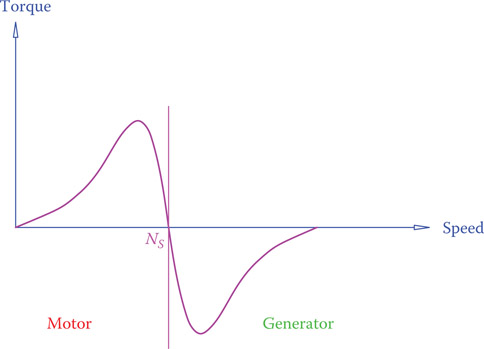
Figure 11.15
Torque-speed characteristic curve of a single-phase induction machine.
As a generator, it is not usual to have a single-phase induction machine used as a generator, except in experimental works and in very limited and isolated cases.
11.6 Induction Motors
In many industries, motors are used for powering pumps, compressors, fans, machine tools, presses, conveyor belts, and so on. In most of these applications induction motors are employed. For this reason it is worth covering induction machines used as motors.
11.6.1 Classes of Electric Motors
Characteristics of torque and power requirement of loads connected to motors are not the same. Some require higher starting torque, and some can be started with lower torque. When a motor starts spinning its load, their speed starts from zero and gradually increases to the operating rpm. The operating rpm is when the torque demand of the load and the torque provided by the motor become equal, and a state of equilibrium is reached. In other words, the operating speed/torque is where the characteristic curve of a load and the characteristic curve of its drive meet. This is shown in Figure 11.16, which also depicts a few terms for the characteristic curve of an induction motor.
Locked rotor torque (LRT): Starting torque in a motor (corresponding to when the rotor speed is zero) or the torque if the rotor is prevented from turning or cannot turn the load.
Pull-up torque: The minimum torque, after starting, in an induction motor that can be provided by the motor. If this torque is not sufficiently higher than that of a load the motor cannot accelerate the load fast enough (see the characteristic curve of a three-phase induction motor).
The starting torque is called locked rotor torque because the speed is zero. If a motor cannot overcome the initial resistive torque on its shaft, it remains at that zero speed (as if the shaft is locked). Associated current in the motor winding is high. Pull-up torque refers to the torque at the point that a motor accelerates and the speed goes up. Pull-out torque, also called breakdown torque, is the maximum torque that a motor can deliver. If load torque is more than breakdown torque at the corresponding speed, motor speed drops and the motor fails to bring the load to its normal operating speed, at which full load torque must be provided.

Figure 11.16
Operating point of a load.
Pull-out torque: The same as the breakdown torque. The maximum torque that an induction motor can provide before reaching its operating speed. The operating speed is within a region where the motor continues to work at full-load torque and the speed variation is proportional to the motor torque (see the characteristic curve of an induction motor.
Breakdown torque: The same as the pull-out torque. The maximum torque on an induction motor speed–torque characteristic curve that can be provided by the motor before reaching the operating speed, where the motor continues to work at full-load torque (see the characteristic curve of an induction motor).
Full load torque: The torque provided by an induction motor at its operating speed. This is the point of intersection of the load line and the motor characteristic curve, and must be sufficiently smaller than the pull-out torque to avoid motor stall.
For the load shown in Figure 11.16, starting torque is lower than operating torque. But this is not always the case and certain loads, like a crane, need a higher torque at the start. A motor must be able to handle starting torque of a load without overheating or giving up. In order not to over design motors for various loads and be able to select the appropriate motor for each job, the National Electrical Manufacturers Association (NEMA) has defined a number of standards for size (frame dimensions), characteristics, and electrical insulation properties of electric motors. (Other equivalent organizations are Underwriters Laboratories [UL] in North America, and International Electrotechnical Commission [IEC] for European countries.) For performance, these are called classes of motors. The most common classes of motors are class A, B, C, and D, which define the expected performance with respect to starting torque, slip percentage, and the like. For a full description of motor classes and other standards, a reader need to refer to NEMA publications.
The most common motor class for many applications is class B, which is characterized by a slip of not exceeding 5 percent and a locked rotor torque of 150 percent the full load torque. The motor current for starting is 600 percent of the full load current. This motor is good for applications such as fans, blowers, and compressors that do not need a high starting torque. Class A has a higher starting torque than class B, and its slip is about the same as that of B, with a maximum of 5 percent. Class C motor has a higher locked rotor torque of about 225 percent of the full load torque but has a higher slip. Class D design is for loads demanding a high starting torque, such as cranes and hoists. The starting torque is 280 percent of the full load torque, and the maximum slip is between 5 and 13 percent. Figure 11.17 illustrates the typical curves for NEMA class motors.
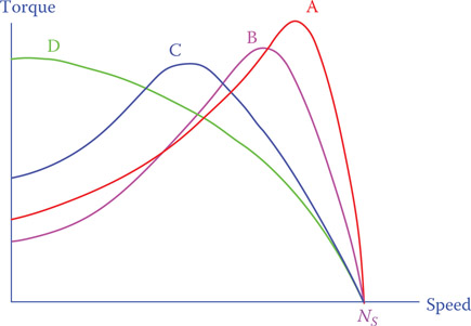
Figure 11.17
Typical characteristic curves of the four most common NEMA motor classes.
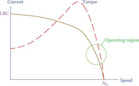
Figure 11.18
Typical current curve in an induction motor.
In an induction motor the stator is connected to electricity. For three-phase motors it can be wye connected or delta connected, as we have discussed in Chapter 8. When the motor is turned on, current starts from the highest value of locked rotor current and decreases to the rated current. Figure 11.18 shows a typical curve for this variation.
Locked rotor current (LRC): Current in a motor corresponding to when the rotor speed is zero (the current at starting a motor or if it is prevented from turning); this is the highest current that the winding in a motor experiences.
11.6.2 Starting of Single-Phase Induction Motors
As said before (see Figure 11.15), a one-phase motor has no starting torque and cannot start rotation on its own when powered. Therefore, it requires some boosting for the instant it is connected to electricity to start turning in the direction it is designed for. After it starts spinning in one direction, it continues running in the same direction. There are a number of ways to start a single-phase induction motor, and these motors are categorized and named by their starting method. The auxiliary device can be connected through a centrifugal switch, which turns it off after the motion starts or it can stay on as long as the motor runs. Motor performance and cost of the auxiliary device are not equivalent for the various starting methods.
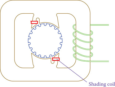
Figure 11.19
Shaded pole motor.
In a split-phase motor a smaller winding is physically put at 90° from the main winding. It is later disconnected after the rotor reaches about 25 percent of its normal speed. Mutual effect of the two windings creates the necessary torque for the motor to start. In very small motors a cheaper method is used, called a shaded pole. In a shaded pole motor an asymmetry is introduced in the magnetic field of the stator by adding two copper straps to each pole, as shown schematically in Figure 11.19. This asymmetry creates the necessary torque to start the motor.
Split-phase motor: Type of single-phase AC motor in which a starting torque is generated by an additional winding in the rotor.
Shaded pole: Type of single-phase AC motor (usually small motors of a fraction of horsepower) based on the creation of an initial (starting) torque by magnetic shading of its poles.
It is very common to use a capacitor in parallel with an induction motor to start it. The phase difference created in the current caused by the capacitor generates a torque that spins the motor. In a capacitor-start motor the capacitor is disconnected by a centrifugal switch after the motor starts. The torque generated this way is larger than that of a split phase motor.
In a permanent split capacitor motor, there is no centrifugal switch and the capacitor stays in parallel with the motor for the entire time the motor runs. It has the extra advantage of improving the power factor of the motor circuit. A capacitor-start capacitor-run motor has two capacitors, one to start the motor and one aimed for power factor correction. In this sense, this motor is a combination of the capacitor-start motor and the permanent split capacitor motor.
Capacitor-run motor: Alternative current type of motor that needs a capacitor in parallel with it in order to work.
11.6.3 Dynamic Braking
The complete speed-torque characteristic curve for an induction machine is shown in Figure 11.20. The additional part in Figure 11.20, compared with that shown in Figure 11.13, depicts the behavior of the machine when the rotor spins in the opposite direction of the rotating magnetic field. If during the operation of a motor the direction of the magnetic field is reversed, the torque on the shaft tries to rotate the rotor in the opposite way, thus adding to the resistive torque on the shaft of a motor. This property is called dynamic braking and can be used in motors to stop a motor faster when it must be stopped.
Dynamic braking: Using the back EMF in a motor for the purpose of braking.
As an example, for a large motor turning a fan, it can take say 10 min before the motor stops after it is switched off. This is because of the large inertia of the motor and its load. Making use of dynamic braking helps bring a motor to a stop much faster. In applying dynamic braking, nevertheless, electricity must be completely disconnected at the moment the motor comes to a stop; otherwise, it starts turning (and speeding up) in the other direction, which is not desirable. Also, a large current flows in the stator winding while dynamic braking is activated.
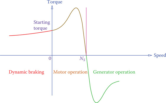
Figure 11.20
Complete characteristic curve of an induction machine.
11.7 Other Motors
Although at the industrial level motors are mostly of the types already discussed, at the consumer level, particularly in the single-phase and smaller category, there exist other types of motors. For example, the motors in a vacuum cleaner or a refrigerator, or inside a CD player, are more likely none of the ones we have studied so far. It is worth briefly describing some of these motors here. We consider only those that can be categorized as AC motors. These motors are universal motor, reluctance motor, and hysteresis motor. Other motors, such as stepper motor (or stepping motor) and brushless DC motors, cannot be directly considered as AC motors, and, hence, they are not discussed.
A universal motor is more common than the other two and is used in many household appliances that need a high starting torque. The reluctance motor and hysteresis motor work based on other principles than have been discussed so far. These motors are sometimes categorized under single-phase synchronous motors because they operate at a constant synchronous speed.
11.7.1 Universal Motor
A universal motor is by no means in the same category as the other motors described in this chapter. However, because many of the small (below 1 hp) motors, in particular those in the common tools and appliances such as a drill or a vacuum-cleaner, are of this type, it is worth mentioning them here. As said before, a universal motor is a series wound DC motor and, therefore, has the same characteristic curve as described in Chapter 7. A universal motor can be distinguished from a single-phase squirrel cage motor by the presence of brushes and a commutator. The rotor may be hidden inside and not be recognizable even in a squirrel cage (where there are no brushes and no commutator).
A universal motor has a smoother operation when fed by DC than when operated on AC electricity. Efficiency is higher and also the brushes last longer.
The following helps to explain how a series wound DC motor can work on both DC and AC electricity. Figure 11.21 can be helpful to clarify the matter. This is not possible in a shunt wound DC machine. You may need to review the Lorentz force and series wound machines in Chapter 7 (see Section 7.4) before continuing.
When connected to DC electricity,
- Direction of the field is constant because the polarity of the field winding does not change.
- Polarity of each loop of the armature winding must change when the loop passes the position indicated as XX′ in Figure 11.21. If the polarity does not change, then the torque generated after a loop has turned 180° will be in the reverse direction. The arrows in the figure show the direction of the forces at various positions of a loop denoted by AB.
- This polarity change is done through the commutator.
When connected to AC electricity,
- Polarity of field winding is switched after each half cycle.
- Polarity of the current in a loop of the armature winding also switches after each half cycle.

Figure 11.21
Series wound motor connected to DC electricity. (a) Series wound motor connected to DC electricity. (b) Forces exerted to one loop of the armature winding.
The mutual effect of the simultaneous changes in the field direction and the current direction cancel each other. The net effect is like having no change in either; that is, what a DC supply provides.
A further polarity change through the commutator is still needed and is carried out as normal for maintaining the direction of the developed torque.
11.7.2 Reluctance Motor
A reluctance motor works on the basis of the reluctance force. A reluctance force, as depicted in Figure 11.22, tries to pull or push a ferromagnetic metal into the magnetic path, so that there is minimum reluctance (or magnetic resistance) in the path. This motor has the same structure as a squirrel cage motor, with the exception that the rotor is deformed in order not to be round or uniformly symmetric. As a result of the shape change of the rotor, when near the synchronous speed, it can snatch into synchronism and continue its motion at the synchronous speed. Thus, the motor starts as an induction motor until it reaches the synchronous speed, at which the principle of operation is reluctance and not induction. Figure 11.23 shows schematics of some typical examples of the rotors for a reluctance motor.
Reluctance force: Force on a ferromagnetic material caused by a magnetic field to minimize the path of magnetic flux.
Reluctance: Equivalence of resistance in an electric circuit in a magnetic circuit; resistance to magnetic flux.
The torque-speed characteristic curve of a reluctance motor and a comparison with that of an induction motor are shown in Figure 11.24. If in operation the magnitude of load torque increases beyond a certain value, then the reluctance motor continues to run as an induction motor.

Figure 11.22
Exhibition of reluctance force. (From Hemami, A., Wind Turbine Technology, 1E ©2012 Delmar Learning, a part of Cengage Learning Inc. Reproduced with permission from http://www.cengage.com/permissions.)

Figure 11.23
Forms of the rotors of reluctance motor.
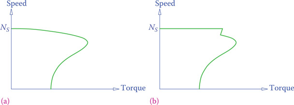
Figure 11.24
Comparison of the characteristic curve of (a) an induction motor with (b) reluctance motor.
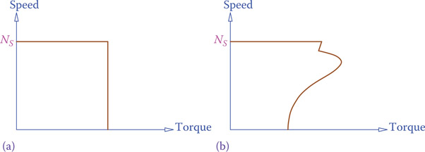
Figure 11.25
Characteristic curve of a (a) hysteresis motor and a (b) reluctance motor.
11.7.3 Hysteresis Motor
The stator of this motor is similar to that of an induction motor (only single phase). The rotor is a uniform cylinder made out of magnetically hard steel (a type of steel that keeps magnetism; it is good for permanent magnet, but not for an electromagnet). Torque developed in the rotor is due to hysteresis effects on the rotor (hysteresis effect is keeping the magnetism). Thus, the torque is constant. This motor has a much better starting torque than the same size reluctance motor. It smoothly increases the speed of a load to the synchronous speed. Pricewise, it is more expensive than a reluctance motor.
Hysteresis motor is characterized by the following features: (1) constant torque, (2) smooth operation, and (3) quiet operation.
Figure 11.25 depicts the typical torque-speed characteristic curve for a hysteresis motor.
11.8 Notes on Application of Electric Machines
An electric machine either converts electric power to mechanical power (motor) or mechanical power to electrical power (generator). It is always power balance between load and drive that determines the equilibrium and operating conditions. If there are controllers for any parameter, such as speed control, they will include their effect with respect to the controlled parameter, but still there must be equilibrium between power of the mechanical system and the electrical system.
For a generator the prime mover (e.g., steam turbine, gas turbine, and wind turbine) provides the mechanical power and the generator is a load for the prime mover. The load on the generator is electrical in this case. For a motor the device connected to it constitutes its load. Thus, for a motor, the load is mechanical.
It is always load that determines power demand, unless drive has reached its maximum capacity and cannot provide more power.
11.8.1 Mechanical Power
We have already seen expressions for electric power in terms of current and voltage for DC circuits and single-phase and three-phase AC circuits (see Chapters 6, 8, and 9). Electrical power demand is always the product of current and voltage; in DC electricity this determines power in watts, and in AC circuits it is apparent power (in volt-amps) that must be provided for a load.
In a mechanical system, power is defined by the parameters in a motion, that is, speed and effort causing that speed. In a linear motion, velocity (speed) is along a straight line and the effort is the component of the force in the velocity direction. This is shown in Figure 11.26. In a rotational system, effort is a torque and speed is the angular velocity. Thus, for a mechanical lifting operation with constant velocity (see Figure 11.26b)
Power = Velocity × Weight
and for any rotating shaft with constant angular velocity
Power = Angular velocity × Torque

Figure 11.26
Power in linear motion. (a) Horizontal motion with constant velocity. (b) Vertical lifting motion with constant velocity.
Therefore
| (11.5) |
| (11.6) |
where P is power, v is the vertical motion velocity, F is the weight of the objected lifted with a constant velocity, ω (omega) is the angular velocity, and T is the torque.
Note that Equation 11.5 is not only for vertical lifting. F can be any resistive force that driving force must overcome. In most cases, where no lifting is involved, this can be the force necessary to overcome friction forces in a system.
Equations 11.5 and 11.6 are complete as shown if P is expressed in watt, v in meters per second (m/s), F in Newton (N), ω in radians per second (rad/s), and T is in Newton-meter (N.m). If the unit for any of the parameters is changed, then a multiplier accordingly appears in the equation. Common customary units for power are watt, kw, and horsepower (hp); velocity can be expressed in m/s and ft/s; force can be in Newton or in pound; torque can be measured in Newton-meter or foot-pound; rotational speed may be expressed in rad/s or revolutions per minute (rpm). For convenience, Equations 11.5 and 11.6 with some other units are given below. The numbers are rounded; for more precision, refer to conversion tables with more decimal digits.
For lifting and linear motion loads,
P (kW) = 0.001 v (m/s) × F (N)
P (hp) = 0.001341 v (m/s) × F (N)
P (hp) = 0.0018164 v (ft/s) × F (lb)
P (kW) = 0.00135451 v (ft/s) × F (lb)
and for rotational loads,
P (kW) = 0.001 ω (rad/s) × T (N.m)
P (kW) = 0.0001047198 ω (rpm) × T (N.m)
P (hp) = 0.000140375 ω (rpm) × T (N.m)
P (hp) = 0.00019014232 ω (rpm) × T (ft.lb)
P (kW) = 0.000141846232 ω (rpm) × T (ft.lb)
In the above relationships the calculated value is the power essential to move or power a load as desired. The power to be provided is more than the required power because of efficiency (see Section 11.8.2). A motor powering its load then must have a higher power to cover for the losses. For a generator, power demand from electrical loads in a circuit determines the power requirement from the generator. Then the prime mover must be more powerful to deliver the power the generator requires as well as the losses. Thus,
| (11.7) |
Torque required to yaw a wind turbine nacelle is 500,000 Nm (369,131 ft.lb). There are eight similar motors to carry out the yaw motion. If the nacelle has to be turned at a speed of 2 rpm, what is the power requirement from each of the eight yaw motors?
Solution
Angular speed is given in rpm, and the torque is in Nm. Hence, power for each motor can be found as
Example 11.3
A motor is used to drive a pump. If at the operating conditions the torque is 150 Nm, the pump rotates at 1150 rpm and its efficiency is 80 percent, what is the pump power requirement? If the pump is to be driven by an AC motor with 90 percent efficiency, what should be the power rating of the motor?
Solution
We may choose horsepower for the unit of power. The net power required by the load (water flow) is
PW = (0.000140375)(150)(1150) = 24.22 hp
Then the power requirement to run the pump is
And the power necessary for the motor is
The rating of the motor should be more than 33.6 hp.
Example 11.4
A conveyor belt is driven by two identical electric motors, each one rated at 12.5 kW. At full load of the belt the two motors work at their rated power. If efficiency of the motors is 90 percent and the belt moves with a speed of 1.4 m/s, what is the resistance force F in the conveyor belt?
11.8.2 Efficiency
No system can be found that is 100 percent efficient, meaning that output power from it is equal to input power to it. Any device, particularly delivering energy of some sort, has an input and an output. Input is power taken by the device to operate; output is what it delivers in the same form or other form of energy or work. Motors and generators fit well into this general definition.
In all electrical, mechanical, and electromechanical systems and devices, there is always some loss of energy in the form of heat due to friction in the moving parts or current in the electrical circuitry. In motors the losses are of two types: those that are fixed, no matter what the load on the motor is, and those that are a function of the load and increase as the current through the machine increases. Among fixed losses are
- Friction in the bearings.
- Windage. This is the aerodynamic losses associated with ventilation fans and rotating parts.
- loss. In both stator and rotor cores, some energy is lost owing to eddy current. The iron core gets warm, meaning that some energy is lost in the form of unwanted heat.
Windage: Aerodynamic losses associated with ventilation fans and rotating parts in an electric motor.
Core loss: Amount of power loss in a transformer or an electric machine that corresponds to the quality of design and core material and is independent of the load current.
Among the variable losses are
- Copper loss, the energy loss in the form of heat in the windings of both the stator and the rotor. This loss is proportional to the square of the current flowing in the winding (or cage bars in a squirrel cage machine).
- Stray loss, the losses of various types that cannot be included in the other categories, including that in the air gap of a machine. It is proportional to the square of rotor current and counts for 1 to 2 percent of the total input power.
Copper loss: Amount of power loss in a transformer or an electric machine that corresponds to the resistance of the wire winding and it depends on the load current (the percentage of loading).
Stray loss: Losses of various origins, including that in the air gap, in an electric machine. These losses cannot be included in the other categories for a machine.
Always, a system input must make up for these losses before an output can be delivered. In this sense, input power Pi to a system is always greater than output power Po from the system. The ratio of output to input is the efficiency, which is always less than 1. Normally, efficiency is expressed in percentage; thus, output to input ratio is multiplied by 100. It is common to use the Greek letter η (eta) to denote efficiency.
| (11.8) |
where Po is the output power and Pi is the input power. In an electric machine, because some of the losses are load dependent, efficiency is not constant. In the design stage of any device or machine, effort is made to have the maximum efficiency. This is usually at the rated operating conditions and for the full load of a machine. The efficiency drops from its maximum value when a machine is not working at its full load capacity.
For motors and generators, normally, the larger a machine, the higher is its efficiency. One obvious reason is that for these machines even 1 percent change in efficiency counts for a large amount of energy involved; thus, considerable time is devoted to its proper design.
Example 11.5
A 10 kW motor is used to turn a shaft at 720 rpm. The motor uses its full power for this load. If the load applies a 120 Nm torque on the shaft, what is the motor efficiency at this load?
Solution
The power required to turn the shaft is
PLoad = (0.0001047198)(720)(120) = 9.05 kW
and the motor efficiency is
Example 11.6
An overhead crane uses a 20 kW DC motor for its lifting operation. Efficiency of the motor is 95 percent and efficiency of the gear system driven by the motor is 85 percent. If a 5000 lb load is lifted by this crane, what is its speed in ft/s?
Solution
According to Equation 7.8, total efficiency is
ηt = (0.85)(0.95) = 0.81
based on which, it follows from Equation 11.3 that
11.8.3 Duty Cycle
Not all motors work continuously during their operation. A pump in a process plant may work 24 hours in a day, but a motor in a passenger lift works only when people use the lift. Similarly, motors in the yaw system of a wind turbine are in operation only when the turbine has to be yawed into the wind. The above pump and its motor are said to have a 100 percent duty cycle, whereas the motor of the turbine yaw system can have a duty cycle of only 20 percent or even less. Some other motors can have more regular work than that of a passenger lift or a wind turbine yaw system. For instance, the fan for the cooling of the gearbox oil in a wind turbine can turn on and off on a continuous basis. Then, by study of the working conditions, one can figure out that on average the fan works 60 percent of the time during summer, for example. The duty cycle of the motor turning the fan, therefore, is 60 percent.
Knowing the duty cycle is important for the selection and operation of a motor. If a motor does not have 100 percent duty cycle, then it has the opportunity to cool down after each cycle of operation, whereas a motor with 100 percent duty cycle does not have such an opportunity. Also, energy consumption of a motor depends on the time that it is in operation.
Other matters also come into consideration for a motor that turns on and off intermittently. Among these are the power factor and the means for power factor correction of the circuit from which a motor is fed, and the spike in the voltage that the motor creates in the circuit when turned on, and its effect on other loads. Each of these must be considered, particularly for large motors, during the design and selection of motors for a particular job.
11.8.4 Back Electromotive Force
Any electric machine has windings, and any winding has both electric resistance and inductive reactance, in series with each other. In this sense the equivalent electrical circuit for each phase winding of the stator of a three-phase electric machine is a resistor and an inductor in series. Resistance of the wire winding is very low. Also, because frequency is rather low (50 and 60 Hz), the value for inductive reactance is also quite low. For example, for a 30 hp, four pole motor running on 460 V, 60 Hz electricity the values for stator and rotor resistance and reactance (see Figure 11.27a) are RS = 0.641 Ω, XS = 0.750 Ω, RRS = 0.300 Ω, XRS = 0.500 Ω, and XM = 26.3 Ω. These are the values as measured or calculated based on the winding inductance.
Connecting a winding, with such a low ohmic resistance and inductive reactance values, to a voltage source of, say, 415 V results in a very high current. In reality, the effect of the turning rotor in a motor significantly reduces such an otherwise high current. The scenario is true if the stator of a motor without its rotor in place is connected to electricity or if the rotor is prevented from turning (braked rotor). In this regard a motor is similar to a transformer; the stator wining is equivalent to the primary winding of the transformer and the rotor winding equivalent to the transformer secondary winding. If the rotor is prevented from turning, the machine behaves as a transformer with shorted secondary circuit; that is, a high current is expected. This is indeed the inrush current of a motor when the rotor starts to turn, which can be several times larger than the normal current.
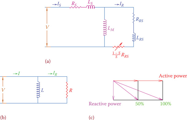
Figure 11.27
(a) Model of an induction machine. (b) Model based on active and reactive elements and their currents. (c) Power relationships at full and half load.
Nevertheless, as we have learned (see also Chapter 7), an electric machine when turned generates electricity. That is, for a motor, at the same time it is rotating as a motor, it also behaves as a generator and generates a voltage in its windings. This voltage is in the opposite direction of the voltage turning it and opposes the applied voltage.
The electromotive force (voltage) generated in a motor winding is called back electromotive force (BEMF) or counter electromotive force (CEMF). If this BEMF in a single-phase motor (or each phase of a three-phase motor) is represented by E, and the voltage applied to a motor is denoted by V, then using Ohm’s law, we have
| (11.9) |
where Z is the impedance of the winding. The BEMF greatly reduces the net voltage across the winding and the current through the winding. Value of E depends on motor speed (as well as other parameters) and becomes larger as speed increases. If the rotor is prevented from turning, then E drops to 0.
(Note that for a generator the same thing happens, but this time the electromotive force E is larger than the terminal voltage V by the value ZI.)
11.8.5 Power Factor Correction
As we have seen in this chapter, the synchronous motor can be run at any desired power factor by changing the excitation current. The induction motor runs with a lagging power factor. Also, we discussed in Chapter 8 that a low power factor is not desirable because it implies loss of energy and a voltage drop in the transmission and distribution lines.
In many industries a large number of motors are used for various processes. Most of these motors are induction motors; thus, it is essential to improve the low power factor of the circuit feeding these motors. The simplified model of a running induction motor is shown in Figure 11.27a. This is for each phase in a three-phase motor. RS is the stator winding resistance, LS is the stator inductance, RRS and LRS are the rotor winding resistance and inductance as seen by the stator (in the same way that the secondary winding values of a transformer are referred to the primary winding), LM is the magnetizing inductance of the stator, and IS and IR are stator and rotor currents, respectively. The last term is a function of RRS. It is variable and depends on the rotor rpm, which can be defined by the slip S, as shown in Figure 11.27a. This model is good for studying the behavior of an induction motor.
For the purpose of power factor correction a simpler model that resembles a resistor in parallel with an inductor is employed, as illustrated in Figure 11.27b. The inductor corresponds to the magnetization effect and the reactive power, and R corresponds to the active power. The power factor of this circuit is improved by inserting a capacitor of proper size in parallel with the other two components (see Chapter 8). To improve the power factor of a motor, the capacitor is put in parallel with the motor. For three-phase motors a bank of three similar capacitors is used. The capacitors can be connected in delta or they can be wye connected, independent of the way the motor is connected.
Reactive power of a motor corresponds to the power required to create the rotating magnetic field. This power is almost constant and independent of whether or not a motor is loaded. Because of this, because a motor can be run at full load or at a percentage of its capacity, its power factor varies and depends on its load. This is shown in Figure 11.27c for full load and 50 percent load of a motor. It is impossible to have a fixed capacitor for power factor correction at all different loading condition of a motor. It is also possible to use a set of capacitors to take care of the power factor correction for a few motors at the same time. It is, generally, very expensive to have a system of capacitors that connect and disconnect according to the load changes in a system, unless cost is justified. Therefore, it is important to have the most suitable capacitor that can compensate for different conditions of a circuit, as a whole. This needs a detailed study of any particular system and its operating conditions.
In the following examples a few scenarios exemplify some general cases of power factor correction for motors.
The three capacitors for power factor correction of a three-phase motor can be delta connected or wye connected, independent of the way the motor is connected.
Example 11.7
Three 470 μF capacitors are connected to a 415 V, 60 Hz line. What is the reactive power of the set if (1) they are wye connected, (2) they are delta connected?
The capacitive reactance of each capacitor is
- For wye connection the voltage across each capacitor is and thus the corresponding current is
and the reactive power can be found in one of the usual ways (see Chapter 9) to be
- For delta connection the corresponding current (phase current) is
and the (reactive) power is
Q = 3IϕVϕ = (3)(7.353)(415) = 9154.49 VAR
which is 3 times the previous value for wye connection.
As can be seen, in wye connection the capacitors are subject to a lower voltage (1.73 times smaller), but their reactive power is 3 times smaller. This is important in selecting capacitors for power factor correction.
Example 11.8
A 20 hp motor is connected to 415 V line. The motor power factor is 0.75 at full load. If the resistance of each of the three wires connecting the motor to the main circuit is 0.5 Ω, determine voltage drop and power loss in the wires for full load operation and compare them with when the power factor is improved to 0.95.
Solution
Current in the wires can be found from the power relationships
From the above relationship, I is calculated to be
I75 = 27.68 A
Voltage drop and the power loss in the wires are, thus,
Voltage drop = (0.5)(27.68) = 13.84 V
Power loss = (3)(0.5)(27.68)2 = 1149 W
If the power factor is corrected to 0.95, then the new current is
And the voltage drop and power loss are, respectively,
Voltage drop = (0.5)(21.85) = 10.92 V
Power loss = (3)(0.5)(21.85)2 = 716 W
(Note: For this problem the nominal voltage of 415 V is assumed to be available at the consumption point. Otherwise, the problem becomes more complicated if the supply line is 415 V before the voltage drop.)
Example 11.9
The power factor of a single-phase 20 hp motor at full load is improved to 0.95 by a set of auxiliary capacitors. If the motor works at 50 percent load, what is the power factor?
Solution
Referring to Figure 11.27c the power to magnetize the stator and the power used by the accompanying capacitor(s) is reflected in the reactive power of the motor. Power that converts to mechanical work is reflected in the active power. The active power, therefore, is 20 hp at full load. We use two methods for solving this problem. One can always use the method that is of preference to him/her.
First method:
Full load
P = Active power = (20)(746) = 14,920 W
50% load
P = (10)(746) = 7460 W
Q = 4904 VAR (unchanged)
Alternative method:
We keep horsepower for the unit of power measurement. From the value of the power factor at this load the reactive power can be determined using the trigonometric relationships (see Figure 11.27c).
Reactive power = Q = Active power × tan θ = P tan θ
θ = cos–1 (0.95) = 18.2°
Q = (20)(tan 18.2°) = (20)(0.3287) = 6.5737 (note that the unit for Q is not VAR now, because P was not in watts)
At 50 percent load, active power is reduced to 10 hp.
θNew = tan–1 (6.573 ÷ 10) = tan–1 (0.6573) = 33.3°
and the new power factor is
pf = cos 33.3° = 0.84
Example 11.10
Three three-phase motors are connected to a 415 V, 60 Hz circuit. The power and power factor of these motors are 8, 10, and 20 kW, and 0.65, 0.70, and 0.75, respectively. These motors work together, and a set of three capacitors can be used to improve the circuit power factor to 0.95. If the capacitors are connected in delta, find the capacitance of each capacitor in the set.
Solution
For convenience and better understanding, the solution to this problem is divided into three steps.
Step 1:
From the given values for the (active) powers and the power factors of the three motors we are able to find the apparent power and reactive power of each motor. We indicate the values for each motor by subscripts 1, 2, and 3 for 8, 10, and 20 kW motor, respectively.
Total apparent power = 53.26 kVA
Total active power = 38 kW
Total reactive power = 37.2 kVAR
It is not necessary to find the power factor for the three motors together, but out of interest, one may want to see how much it is. It is
which corresponds to a phase angle of about 45°.
Step 2:
On the basis of the desired power factor, determine the total apparent power for the same active power of the motors.
and the new total reactive power is
The difference between the previous value and the new value of the reactive power is the power of the capacitors to be added to the circuit.
Capacitor power = 37.2 − 12.5 = 24.7 kVAR
Step 3:
On the basis of the power for the capacitors find their capacitance, taking into account the way they are going to be connected, delta or wye.
For delta connection the current in the capacitors circuit is (based on Equations 9.12 and 9.13):
On the basis of this current the capacitive reactance for each capacitor is found:
and the capacitance of each capacitor is
If we face difficulty finding the right capacitor, we may want to see what size capacitor is needed if wye connection is employed.
For wye connection, voltage applied at each capacitor is smaller , but we still need to have the same reactive power for the capacitor bank. In such a case the current is
leading to
The capacitor size is, thus,
The capacitors to add to the circuit for wye connection are 3 times larger in size, which result in a capacitive inductance 3 times smaller. Voltage rating of the capacitors is, nevertheless times smaller. The current in the lines connecting to the capacitors is still the same as in delta connection. (Note that the phase current for the capacitor lines is times larger than before, but the line current is the same, because, for delta, the line current is times the phase current; see Section 9.5.1.) But, the reactive power introduced by the insertion of the capacitors is the same as desired.
Example 11.11
For the expansion of the plant in the previous example a 30 kW (40 hp) motor is needed. A decision has been made to use a synchronous motor and retire the capacitor banks. All the motors are delta connected. Determine at what power factor the synchronous motor must work so that the power factor of the entire system at full load is 0.95.
For ease of reference, all the pertinent values of the three induction motors are shown in the following table:
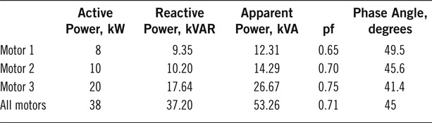
With the addition of the new (synchronous) motor the total active power is (38 + 30 =) 68 kW, and on the basis of the desired pf of 0.95, apparent and reactive powers can be determined.
To bring 37.20 lagging reactive power to 22.35 lagging reactive power, the amount of leading reactive power to be added is
37.20 − 22.25 = 14.95 ≅ 15 kVAR
This reactive power must be provided by the synchronous motor. The synchronous motor, therefore, must work with a leading power factor of
11.8.6 Nameplate Information
Any motor has a nameplate attached to it that gives the rated values and other pertinent information about the motor and its operation. The following list gives the most common information found on the nameplate of a motor. Most of the items are self-explanatory.
| Type | High Efficiency | Frame | 286T |
| hp | 38 | Service factor | 1.1 |
| Amp | 44 | Volts | 415 |
| rpm | 1750 | Hz | 60 |
| Duty | Continuous | Cos ϕ | 0.89 |
| Class Ins. | F | NEMA design B | |
| 3-ph Y 4-pole |
The type is a categorization of various motors based on the form and size of the squirrel cage bars. The frame number and class of insulation are other NEMA classifications similar to design B. These deal with design of a motor for various ambient conditions, like humidity and existence of combustible gases. There are also many other NEMA specifications such as TEFC (Totally-Enclosed, Fan-Cooled), but they are out of the scope of this book. For more details, refer to NEMA publications or other standards for motor. Service factor is the percent of the maximum allowed power that a motor can withstand for a short period of time without overheating and getting damaged.
Among the information for a motor is the direction of rotation. It is shown on the motor frame (not on the nameplate) somewhere near the shaft.
11.9 Chapter Summary
- There are two principal categories for many AC motors, synchronous motors and asynchronous motors.
- Asynchronous motors are better known as induction motors.
- A synchronous motor always has a constant speed.
- A synchronous motor always turns at the synchronous speed, which depends on the line frequency.
- An induction motor always runs at a lower speed than the synchronous speed.
- In induction machines the rotor is either a wound rotor or a squirrel cage rotor.
- Synchronous speed for a machine depends on the number of poles (in addition to the line frequency).
- Any AC machine is either single or three-phase.
- AC motors do not have a commutator. This is the way to distinguish between AC and DC motors. However, a universal motor works with both AC and DC electricity.
- A universal motor is a series wound DC motor, but because of its electrical structure, it can work with AC, too.
- AC motors and AC generators have the same structure.
- All three-phase machines work based on rotating magnetic field.
- In most AC machines, particularly the large ones, the stator is connected to the electricity circuit not the rotor.
- A three-phase machine is smaller and works smoother than its same power single-phase counterpart. In any electric machine, power is proportional to the product of voltage and current.
- In a mechanical system, power is proportional to the product of speed and either force (for linear systems) or torque (for rotational systems).
- In a three-phase motor, swapping two connections changes the direction of rotation. A motor must have been designed for operating in both directions.
- In a single-phase motor one cannot change the direction of motion.
- Single-phase induction motors need an auxiliary device for their start. They are categorized and named based on their starting method.
- Power for a generator is in volt-amp, but for a motor it is in kW or horsepower.
Review Questions
- What are the two main categories of AC machines?
- Is there a motor that can work with both AC and DC electricity?
- What are the units for measuring power in motors?
- What is the difference in construction between a motor and a generator of the same category?
- How can you judge if a motor and a generator are compatible?
- What is a synchronous speed?
- Is there only one synchronous speed? If yes, what is it?
- Does a synchronous motor run at a synchronous speed?
- What are the parameters defining a synchronous speed?
- What is the part of an AC machine that rotates called?
- What is the rotating magnetic field?
- What is the other name for an induction machine?
- If a motor has six terminals (six wires to be connected to electricity), does it have six poles?
- How many terminals does a single-phase machine have?
- What is the main difference between a synchronous machine and an induction machine in operation?
- How do you know if a motor is AC or DC?
- In a motor, what does the term operating conditions mean?
- What do the terms rated voltage, rated power, and rated frequency mean?
- How do you know if an AC motor is three or single phase?
- Why is the starting current in a motor higher than its rated current?
- If a motor is made for 60 Hz, can you use it with 50 Hz electricity? Why or why not?
- Why must a synchronous generator always be run at a synchronous speed?
- Mention some of the synchronous speeds for 60 Hz.
- Describe some of the synchronous speeds for 50 Hz.
- Can a three-phase induction motor start by itself?
- If a motor cannot start by itself, what can be done to start the motor?
- For a single-phase motor, what are the usual starting methods?
- If the rated speed of an AC motor is 1100 rpm, what type of a motor is it?
- What happens if you connect two of the three wires of a three-phase motor to a three-phase line?
- What happens if you connect two of the three wires of a three-phase motor to a single-phase line of compatible voltage?
Problems
- Find the synchronous speed of an induction motor with 24 poles, when connected to a 415 V, 60 Hz line.
- What is the rotating speed of the motor in Problem 1 if it has a 4 percent slip?
- What is the rotating speed of the motor in Problem 2 if it is connected to a 50 Hz line?
- If an induction motor rotates at 960 rpm, can you determine the line frequency?
- Determine the total number of poles in the motor in Problem 4.
- Find the reactive and real (active) power in a single-phase motor that when connected to 120 VAC, the current is 1 A, and the power factor is 0.8.
- A 2 kW, 220 V, 50 Hz, single-phase AC motor has a power factor of 0.77 at full load. What is the current for the line connecting the motor?
- What is the current for the motor in Problem 7 at 80 percent load if the power factor for this load is 0.72?
- In Problem 8 if the power factor is improved to 0.95 (for 80 percent load), what is the power factor when the motor is at full load?
- Three of the motors in Problem 7 are used and work together on a 380 V, 50 Hz circuit. A single capacitor is used to correct the power factors of the three at full load to 95 percent. Determine the capacitance of the capacitor.
- If after the insertion of the capacitor one of the motors in question 10 is turned off, what is the line power factor?
- If each line connecting the motors in Problem 10 has 0.5 Ω resistance, what is the voltage drop in the line before and after the power factor is corrected to 0.95?
- A three-phase motor is delta connected to a 415 V, 60 Hz line. If the line current is 25 A and the motor power factor is 0.75, how much power is consumed by the motor?
- Determine the size of the bank of three capacitors to improve the power factor of the motor in Problem 13 to 0.95. The capacitors are delta connected.
- If two of the motors in Problem 13 work together, what is the size of capacitors to correct the power factor to 0.95 if delta connected?
- For the motors in Problem 15 compare the voltage drop in the line between the two cases that the pf is or is not corrected. The total resistance of each wire is 1 Ω.
- If the efficiency of the motor in Problem 13 is 93 percent, how much mechanical power is available on its shaft?
- At a particular time, a wind turbine absorbs 1750 kW of power from wind. Efficiency of the gearbox is 90 percent and efficiency of the generator is 95 percent. What is the output of the generator?
- If the generator in Problem 18 works at a power factor of 0.94, what is the current in the line between the generator and its transformer if the generator is fully loaded (all its output is used)? The generator voltage is 600 V, and it is delta connected.
- What is the maximum current the generator in Problem 19 can deliver when it absorbs only 1 MW power from wind? All the other numbers are unchanged.