Chapter 2
Understanding Signal Flow
IN THIS CHAPTER
![]() Understanding the mixer
Understanding the mixer
![]() Deciphering channel strips
Deciphering channel strips
![]() Exploring routing and busing
Exploring routing and busing
If you’ve ever been to a recording studio and watched a great recording engineer create a mix, you’ve probably been entranced by how he or she interacted with the mixing board: a dance around the mixer, a twist of a knob here, a push of a slider there. All this to the beat of the music. It’s like watching a genius painter paint, or a great orchestra conductor conduct, or a brilliant surgeon surge … er, operate. I’ll even bet that one of the reasons you got interested in home recording is so you can have a chance to play with those knobs yourself. Go ahead and admit it — you’ll feel better.
Well, you get your chance in this chapter. Not only do you discover what each of those knobs does, you get a feel for all the functions that the mixer fulfills in the studio. You discover what makes up a channel strip and how it’s used. You get a chance to see how routing works (and even discover what routing is). And you see how digital mixers use fader banks to provide numerous functions while taking up very little space.
Meeting the Many Mixer Types
Pro Tools has an integrated mixer as part of its software, with which you can effectively do anything that you can possibly want (and more) with your music. You can adjust equalizers (EQ), levels, panning, and routing (to name just a few) by either using keystrokes on your computer keyboard or administering a click of your mouse.
Even with all the power that the Pro Tools mixer has, some people (myself included) like to have some knobs to twiddle and some faders to slide while they work. If you’re one of these people, the following sections help you decide which of the three hardware options would work best for you.
Analog mixer
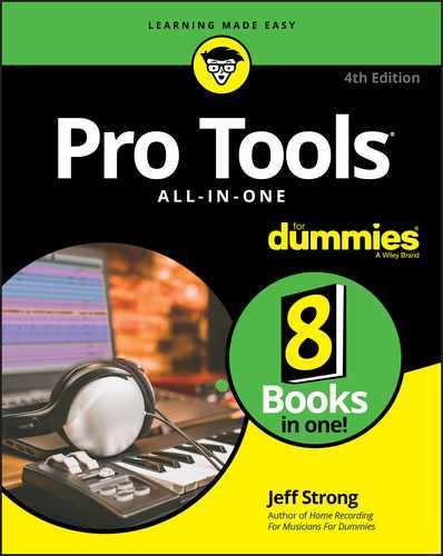
An analog mixer, as shown in Figure 2-1, enables you to route the signals within the analog domain. Analog mixers tend to have many knobs, lights, and faders — a set for each channel. If you want to change from mixing inputs (your instruments) to mixing sounds recorded on the recorder, you need to plug and unplug cords, or you need to get a mixer with twice as many channels as your recorder.
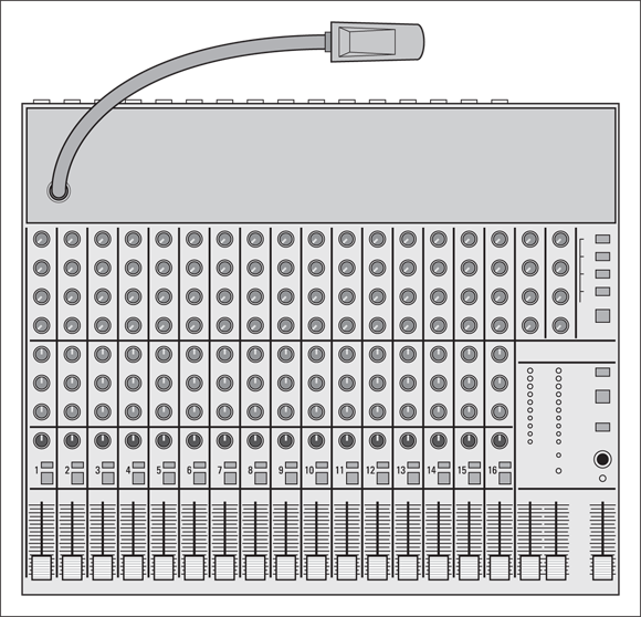
FIGURE 2-1: An analog mixer has tons of knobs, lights, and faders to play with.
Many people prefer analog mixers because they believe they produce better sound than the mixer in Pro Tools software (not necessarily the case, at least to my ears), or they want to create elaborate mixes for a band to hear in their headphones while they record.
The main disadvantage to using an analog mixer with Pro Tools (or any other computer-based recording system) is that you need just as many analog inputs and outputs for your audio interface as you want channels to mix in your mixer. For example, if you want to mix a 16-track song, you need the equivalent of two MOTU 828x interfaces, assuming your interface allows you to hook up two at once. At the time of this writing you are limited to just one. (For more on audio interfaces, check out Book 1, Chapter 2.) The other possible disadvantage is that each analog-to-digital-to-analog conversion degrades the sound of your music.
Digital mixer
A digital mixer, as shown in Figure 2-2, is a great option for Pro Tools users because it can perform the same functions as a conventional analog mixer in a lot less space, and you don’t have to worry about having as many analog connections. Also, the whole issue of sound degradation from going back and forth to digital is moot because all your music stays in the digital domain.
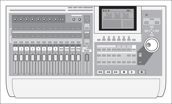
FIGURE 2-2: A digital mixer performs the same functions but takes up less space than an analog mixer.
 If you want to use a digital mixer with Pro Tools, make sure that it’s compatible with the software — an easy task if you go to
 http://avid.force.com/pkb/articles/en_US/Compatibility/en353265 (Windows) http://avid.force.com/pkb/articles/en_US/Compatibility/en436391 (Mac) — and that you have enough channels of digital connection in your hardware. Like in Pro Tools software, routing — sending your signals to various places within the mixer — becomes almost easy using a digital mixer. You can switch between input and track channels without having to change a single cord.
One of the great things about digital mixers is that any EQ or effects plug-ins that you use are powered by the processor in the mixer, not the processor in your computer. This can allow you to have many more effects on your mixes (not always a good thing) before your system bogs down.
The downside to this arrangement is that you’re stuck with the EQ and effects that are part of your mixer. If they aren’t that great to begin with, you may not want to use them.
The computer control surface
A computer control surface is a piece of hardware that interfaces with your computer to control the controls within the Pro Tools software. As far as I’m concerned, a computer control surface, like the Artist Mix, is the way to go with Pro Tools — as long as you have a powerful-enough computer to handle the mix — because all your EQ and effects processing is still done in the computer, unlike what you’d get with a digital or analog mixer. (Book 1, Chapter 1 has more on what constitutes a powerful-enough computer.) Quite a few control surfaces integrate smoothly with Pro Tools, including the cool-looking Artist Mix shown in Figure 2-3.

Courtesy of Avid
FIGURE 2-3: A computer control surface acts like a digital mixer for a computer-based system.
Before you buy a control surface from another manufacturer, check out the compatibility page at the Avid website at http://avid.force.com/pkb/articles/en_US/Compatibility/Pro-Tools-System-Requirements to make sure that the one you want works with Pro Tools.
These controllers send MIDI messages — coded with the Musical Instrument Digital Interface communications protocol — to the computer telling it which parameters to change. These controllers can easily be programmed to work like a separate digital mixer.
Understanding Mixer Basics
In spite of the many types of mixers out there (see the “Meeting the Many Mixer Types” section, earlier in this chapter), you’ll discover that they all generally follow the same basic principles and have a number of elements in common. You’ll also discover that regardless of the type of mixer you use, two mixing aspects — the channel strip and busing (routing) — are universal. The rest of this chapter concentrates pretty heavily on these two aspects.
 Think of a mixing board as a sort of air-traffic controller for the audio world. Just like how the guys and gals in the towers near an airport communicate with all the planes in the air, making sure that collisions are avoided and that traffic moves quickly and efficiently, the mixer routes all the incoming and outgoing signals from the instruments, effects, and recording devices so they get to their desired destination without any problems.
Channel strip
The mixer is composed of numerous channels into which you process the signal of an instrument or microphone before it’s sent to the recorder. This is the channel strip. (See upcoming Figure 2-6.) Even though the mixer may look confusing with all its knobs, lights, and sliders, you need to understand the basic makeup of just one channel to understand them all. The channel strip’s job is to take the signal from an instrument or microphone and send it where you want it.
The channel strip also enables you to make adjustments to the level of the signal in a variety of ways: overall level, a certain frequency’s level (different for each mixer), left or right stereo level, and effect levels.
The channel strip serves two functions:
- To control the level of an input device (input channel)
- To control the level of a recorded track (track channel)
Both functions of the channel strip operate the same way. In fact, you can use the same channel for either an input or a track signal. The only difference is which device (an instrument or the output from your recorder) is plugged in.
Input jack
An input jack, generally located on the back of the mixer (although it can also be on the upper part of the top of the mixer), is where you plug in your instrument (or microphone or the output from your recorder). Many professional mixers have both a quarter-inch and an XLR jack for each channel. (See Figure 2-4.) For the lowdown on jacks, read through Chapter 1 of this mini-book.
FIGURE 2-4: Input jacks on the back of a mixer accept instruments, recorder, and microphone sources.
A ¼-inch jack is used for line-level sources, such as a synthesizer, a drum machine, or the cord from the Line Out of your guitar amp. An XLR jack is for the male end of the microphone cord. Most semi-pro and pro mixers also have phantom power available to a XLR jack. The phantom power feature sends a low level of current from the mixer to the microphone to get the microphone to produce a signal. Phantom power is necessary for professional condenser mics.
If you choose not to mic your guitar amp and instead want to plug your guitar directly into your mixer, you need to do one of three things:
- Plug your guitar into your amp and run a cord from the Line Output of the amp to the mixer’s channel input.
- Plug your guitar into a direct box (a device that changes the impedance level of your guitar or bass; Book 1, Chapter 1 has more on this) and plug the direct box into the channel input of your mixer.
- Plug your guitar directly into the hi-Z input (high impedance) of your mixer, if it has one. (You’ll find this feature on many newer mixers.)
Most pro mixers allow you to use either a balanced or unbalanced cord. (For the scoop on balanced and unbalanced cords, see Book 2, Chapter 1.) Read through the owner’s manual for your mixer to find whether balanced connections are part of your mixer’s specs. Balanced connections are important only if you have really long cords (longer than 25 feet, for instance) because they cut down on the noise that can result from long cord runs that use unbalanced cords.
Insert jack
Aside from quarter-inch and XLR input jacks, another jack — an Insert jack — is often found on the back of the mixer for each channel. Its purpose is to enable you to send the signal from the channel out to a processor, such as a compressor or an EQ , and to receive the signal after it’s processed. Unlike the Effect Send (as described in the upcoming section on Auxiliary Send knobs), this jack won’t let you mix in as much effect signal as you want — all the signal is affected. Figure 2-4 shows a typical set of input jacks.
Insert and input jacks are different, serving two very different purposes. An Insert jack is a bit of a hybrid — it’s an input jack as it acts as both an input and an output (which explains the cord that is used for it), but it still resides in the input section of a mixer, in this case below the XLR and Line input jacks.
To use the Insert jack, you need a Y cable, as shown in Figure 2-5. You connect the plug at the base of the Y to the mixer Insert jack; the plugs on the two arms of the Y go into the input and output jacks of the processor.
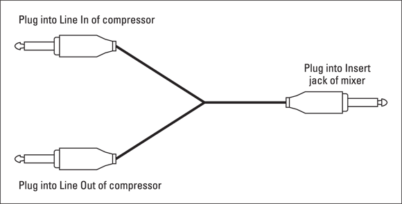
FIGURE 2-5: Connecting a signal processor to the channel’s Insert jack.
Trim knob
The job of the Trim knob (labeled as Gain on your Avid interface) is to adjust the level of the input signal as it enters the mixer. (You usually find the Trim knob at the top of the front panel of the channel strip, as shown in Figure 2-6.) The amount that you adjust the Trim knob depends on the instrument that you plugged in to the channel strip; so be sure to listen as you make your adjustments.
If the Trim knob is set too high: You get distortion.
If the Trim knob is set too low: You get too weak of a signal to record.
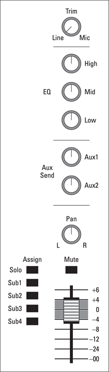
FIGURE 2-6: Use the mixer’s channel strip to make many adjustments to your source signal.
Most Trim knobs have a switch or markings for Line or Mic(rophone) signals. See these markings in Figure 2-6. Turn the knob all the way left for line sources — or slowly keep turning it right for microphone sources — until you get a nice, clean sound coming into the mixer. See Book 3, Chapter 3 for more on setting your input levels.
If you choose to use an external preamp, check the owner’s manual of your mixer to see whether you can bypass the internal preamp. Most professional mixers enable you to do this. Sometimes just having the Trim knob all the way down (to the Line marking) disengages the preamp from the circuit — and this is the case with the Avid preamps. You can also plug in to the line inputs if you want to keep your Avid preamps free for other mics or instruments.
Equalization
Semi-pro and pro mixers give you the opportunity to adjust the equalization (EQ) of your signal — that is, to boost or reduce specific ranges of sound frequency. Less expensive mixers have fewer equalizer settings (as few as two — one for high frequencies and one for low frequencies). Pro mixers have three or four; digital mixers and software mixers may have more.
Channel Auxiliary (Aux) Send knobs
You may want to add an effect such as reverb or delay to the signal coming into your mixer. With effects such as reverb, you don’t want to use the Insert jack — like you would with a compressor — because you want to be able to control how much of the effect you actually hear. (Compressors affect the entire signal, not some portion of it. You can find more about compressors in Book 6, Chapter 4.)
This is where the Auxiliary (Aux) Send feature comes in. That’s what the little knobs in the middle of the channel strip in Figure 2-6 are for. Adjust these knobs to send as much (or as little) of the signal as you want to go to the appropriate auxiliary component (Aux, get it?). Doing so specifies how much (or how little) of the effects processing shows up in your final sound. Turning the knob to the left produces less effect; turning it to the right gives you more effect.
Not only can you set the Effect Send level at each channel (and you can send more than one channel’s signal to each effect), you can also adjust the level of the affected signal that’s brought back into the mixer and mixed with all the dry signals at the master bus. (See the “Routing/Busing Signals” section later in this chapter.) This is the Aux Return, which you can find out more about in the “Auxiliary (Aux) Return knobs” section, later in this chapter.
Pre/Post switch
The Pre/Post switch enables you to send the signal to the Aux bus (through the Aux Send knobs) either before (pre) it gets through the EQ and channel fader or after (post) it goes there. Use the Pre/Post switch to send an unequalized signal to the effect, and then to adjust the EQ of the dry (unaffected) signal without affecting what the effect sounds like. You can also use the Pre/Post switch to control the level of both the signal and the effect with the channel fader.
Having this option gives you more flexibility to control what the affected sound will sound like. For example, you can send the dry signal of a kick drum to a reverb (with the switch in the Pre position) and then boost the bass on the dry signal. Doing this gives you some reverb on the higher frequencies without adding it to the lower ones, which would create some mud in the final mix. The downside to this technique is that you can’t use a fader to control the level of the signal being sent to the effect. (You bypassed the fader in the Pre position.) In this case, if you raise and lower the channel fader, the amount of effect that you hear in relation to the dry signal will change as well. For example, when you lower the fader, you hear more effect because less of the dry signal is mixed in. Comparatively, when you raise the fader, you hear less effect because the dry signal is louder and the effect level is the same.
Pan knob
Use the Pan knob to adjust where in the stereo field (how far left or right) your signal is heard. This knob is generally located toward the bottom of the channel strip and is an important part of mixing. Where you put something in the stereo field has an effect on how well it’s heard among all the other instruments playing through the mixer. (Book 6, Chapter 1 has more details on panning and mixing.)
Mute switch
The Mute switch, located toward the bottom of the channel strip, enables you to silence (mute) the channel. This switch is commonly used during mixdown to help you work with the sound of a particular part in the mix. This switch allows you to quickly silence the parts you don’t want to hear when you’re mixing so you can concentrate on the sound of the instruments that you want to hear. For example, when you work in EQing and balancing the levels of the drum set, you can use the mute switch for all the other channels so you hear only the drum set tracks.
Solo switch
The Solo switch, when engaged, allows one channel to “sing solo” while muting all the rest. This switch (normally located near the Mute switch) is also commonly used during mixdown when you want to hear only one instrument. This saves you the hassle of having to press the Mute switch on all the rest of the channels. For example, when you work on EQing and are affecting the lead vocal, you can press the Solo switch to mute all the other instruments while you make your adjustments. Then, when you want to hear what your adjusted vocal sounds like with the rest of the instruments, all you have to do is disengage the Solo switch (press it again).
Assign switches
The Assign switches can be located just above the fader, at the top of the mixer, or right next to the fader. Use these switches to choose where to send the outgoing signal. You can send it to the Master bus or to any of the submix buses. (For more on buses — the electronic pathways along which signals are sent — see its upcoming section.) If your mixer doesn’t have a separate Solo switch, one of the Assign switches can give you the option of soloing that channel.
Faders
A fader, usually a slider control located at the bottom of each channel strip, determines the overall level of the signal coming out of the channel strip before it makes its way to the recorder, the Master bus, or the Submix bus. (Check out the following section for more details.)
Routing/Busing Signals
After you have an instrument plugged in to the mixer channel strip, you want to send that signal somewhere. This is routing or busing. (The place where the signal ends up is, conveniently enough, a bus.) Most mixers offer numerous busing possibilities, including busing to the
- Master bus: Send your mixed music to a two-track recorder.
- Submix bus: Mix several tracks before they go to the Master bus.
- Control Room bus: Listen to the tracks through your monitors.
- Auxiliary bus: Add an effect to your signal.
In the following sections, I introduce you to some of the most used busing options and describe some ways to make this process easier.
The busing controls are generally located on the right side of the mixing console, as shown in upcoming Figure 2-7. Here you have faders for the Master and Submix (Sub) buses; dials for the Aux bus; and Solo and Mute buttons for the Master and Submix (Sub) buses. This area is often called the master control section of the mixer.
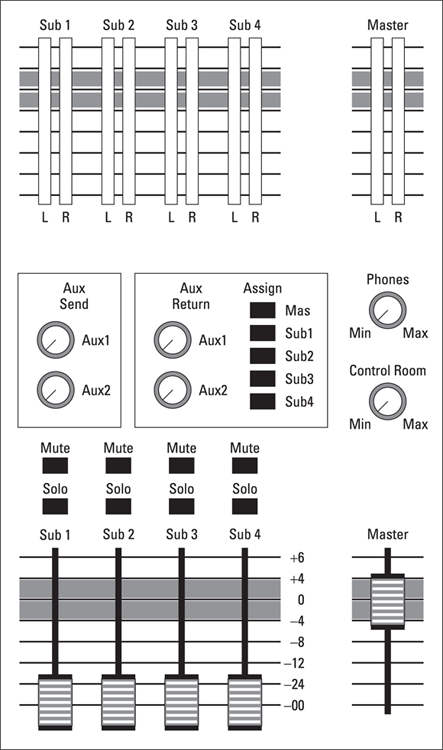
FIGURE 2-7: The master control section of a mixer controls the routing of the signals coming from the channel’s strips.
Master fader
A Master fader, located in the lower-right corner of Figure 2-7, controls the Master bus, where your mixed music goes out to the 2-track recorder or back into Pro Tools. When you have something plugged in to a channel input, it’s automatically sent to the Master bus. Where you have your Pan knob set for each channel (how far to the left or right) dictates how much signal is sent to the left or right channels of the Master bus. Some mixers are designed with only one Master fader to control all channels, both left and right; on other mixers, you have one fader for each left and right channel.
Sub (submix) faders
Depending on the mixer you own, you may or may not have a group of Sub (submix) faders located to the left of the Master fader (refer to Figure 2-7). Submix faders control the Submix buses, which is where you can mix several of your tracks and group them independently of the rest of the tracks. You use the Assign switches for each channel to choose which (if any) Submix buses you want the signal sent to.
The submix can be sent out of the mixer as a unit. For example, you may want to record all the drums on one or two tracks instead of recording them individually. The submix is also routed to the Master bus as a unit. If you assign instruments to a submix, they get diverted from the Master bus and go to the Submix fader first. Then everything assigned to that Submix fader gets sent to the Master bus to be controlled by the Master fader. Most mixers also allow you to send the submix out without having to go through the Master bus first; often the Submix outputs are located on the back of the mixer.
Solo/Mute switches
Above each Submix fader on your mixer, you’ll most likely have Mute and Solo switches, as shown back in Figure 2-7. Use these switches to, well, solo or mute (that is, isolate or silence) the submix group. For example, you may want to hear only the submix of the drums or maybe background vocals. This switch allows a quick check of your submix.
Control Room level knob
The Control Room level knob, usually located above the Master fader (refer to Figure 2-7), controls the level of the signal going through the Control Room bus — the signal that’s sent to your studio monitors. The Control Room level knob is fed by the Master bus and has the same mix that goes through the Master Output to your recorder. This allows you to monitor your mix at a different volume from that of the master level being sent out through the Master bus.
The Control Room level knob is especially useful when you’re recording and sending a high level to the recorder but also want to listen to what’s being recorded — at a more comfortable, lower volume — through the monitor speakers.
Phones knob
Like the Control Room level knob, the Phones knob (located above the Control Room level knob in Figure 2-7) enables you to adjust the level going to the headphones independently of the master level. The Phones knob is fed by the Master bus and has the same mix as the Master fader.
Auxiliary (Aux) Send knobs
The Aux Send knobs, also located in the master controls section of the mixer, allow you to send the entire mix from the Master bus to an effects processor, such as a reverb or delay. Looking back at Figure 2-7, you can see the Aux Send knobs above the Submix fader on the left.
Auxiliary (Aux) Return knobs
The Aux Return knobs control the overall level for each of the signals routed through an effects processor and sent back to the Master bus. You use these knobs to mix in the amount of wet (affected) signal that you want. The wet signal mixes with the dry (unaffected) signals from each of the channels.
Aux Assign
Some mixers can route a signal sent through an effects processor to any of the submix buses, where they can be controlled by the corresponding submix fader. This Aux Assign capability enables you to have (for instance) the reverb you want on the drums routed to the Submix fader that controls the overall drum level. You choose your bus by pressing in the corresponding Assign button.
Master Level meters
At the top of many mixers are the Master Level meters, which keep tabs on recording levels and warn you when you may be producing a signal that’s too strong or too weak. Too strong of a signal can lead to distortion; too weak of a signal produces a sound that lacks fidelity (sounds thin). Master Level meters can come in the form of VU (volume unit) meters (the ones with needles that go back and forth) or as LED lights (where green is good, and red is bad).
Deciphering Output Jacks
Most mixers have a bunch of output jacks (where — you guessed it — the signal comes out) located at the left on the back of the mixer, as shown in Figure 2-8. You often find output jacks for the Master bus, headphones, monitors, and Direct Outs for each channel, as well as jacks for the Aux Returns.
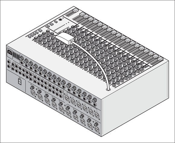
FIGURE 2-8: Mixers usually have their output jacks in the back.
Master Out jack
The Master Out jack goes to the power amp for your speakers or to a mastering recorder (2-track). This jack is controlled by the Master fader and sends the signal that’s routed through the Master bus.
Phones jack
The Phones jack is for your headphones and is fed by the Phones knob on the master console, which carries the same signal as the Master bus — only you get to control the volume separately.
Monitors jack
The Monitors jack is where you plug in your monitor speakers. Control this jack with the Monitor (or Control Room) knob on the mixer. It carries the signal from the Master bus to the speakers.
Direct Out jacks
You get Direct Out jacks on more full-featured mixers. These jacks are controlled by their corresponding channel fader (Channel 1 goes to Direct Out 1, Channel 2 to Direct Out 2, and so on). The signal goes directly out from each channel without going through the Master bus.
 Most semi-pro and pro mixers won’t actually have a Direct Out for each mixer channel. That’s no big deal because Direct Out jacks are designed so you can send a signal directly out (hence the name) from the channel to a recorder. If you don’t have Direct Outs on your mixer, you can just use the Insert jack to send your signal directly out of the mixer and into the recorder. The exact procedure for this connection depends on your mixer; check your owner’s manual.
Direct Out jacks are really helpful when you’re recording with overdubs, when you layer a track by recording one instrument at a time. For example, you can record the drums on Channels 1–4, the bass guitar on Channel 5, and the guitar part on Channel 6. You then send the signal via the Direct Outs from Channels 1–6 to the recorder’s Tracks 1–6 and send those signals back to the mixer on Channels 9–14. You can then use Channel 7 to record the lead guitar part to Track 7 of the recorder while listening to Tracks 1–6 on Channels 9–14. This saves you from having to crawl behind your mixer and change cords when you want to hear the recorded track.
As you can see, the mixer setup can get complicated. Don’t worry. After you get to know your mixer and get a chance to try some different routing configurations, this stuff will become second nature to you.
Aux Return jacks
Aux Return jacks are where you plug in the cord from the Line Out jack of your effects processor. This jack is fed to the Aux Return knob.
Making Life Easier with a Patch Bay
After you set up your mixer and plug it into the input devices, effects processors, and recorder, you’re set to go. But what if you want to record a track and then listen to it right away to see whether you like what you hear? Well, for most home recordists, this can be a problem because you’ll most likely have only enough channel strips in your mixer for either recording or for listening. If this is the case, you have to crawl behind the mixer and unplug your input device and then plug in the outputs from your recorder. Then, when you’re done listening, you have to switch the cables back to record again. All this crawling and connecting can be time-consuming (and eventually hard on your cables).
The solution is to get a patch bay — a device that consists almost entirely of input and output jacks. You plug your gear into it so you can change the cord configuration without crawling around behind your big pile of technology. Check out Figure 2-9 for a look at a patch bay.
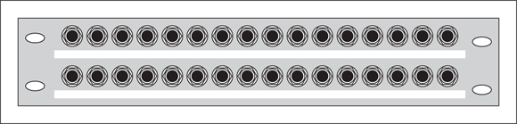
FIGURE 2-9: Use a patch bay to avoid plugging and unplugging gear.
An essential tool for analog studios, a patch bay is also useful for the more complicated digital studios as well. Patch bays function by giving two series of jacks:
- One in the back where you plug in all your gear
- One in the front that you can use to patch — connect with cables — any one piece of gear into any other
For example, imagine that you want to plug in the output from your synthesizer into Channels 1 and 2, and you want to record your friend’s guitar on Channel 3. At the same time, you want to monitor the bass guitar on Channel 4 and the drums on Channels 5–8. This is pretty straightforward, but what if you want to hear what you recorded on Channels 1–3? With a patch bay, all you have to do is change the cords going into mixer Channels 1–3 at the patch bay.
You still have to change cords when you use a patch bay, but at least everything is up front and accessible; without a patch bay, you’re stuck having to crawl behind your mixer and recorder to change the cords.