Underground coal gasification
Abstract:
Underground coal gasification (UCG) is essentially the same well known chemical processes used in surface gasification that converts solid coal into a mixture of gases known as synthesis gas (or syngas). Rather than taking place in an expensive, purpose built reactor vessel, however, UCG takes place in coal seams while they are still buried deep underground. With a century of experimentation behind it, UCG is not a new technology. Relatively recent advancements in key enabling technologies have allowed UCG to develop into a safe, economic energy technology that is now at the stage of becoming commercialised in many countries around the world. This chapter contextualises the recent resurgence of interest in UCG, drawing on the lessons learnt from previous trials on aspects such as environmental risk management, and the impact of new technologies on the development of UCG.
8.1 Introduction
Since the early 1930s, underground coal gasification (UCG) has promised a revolution in the safe, economic recovery of vast reserves of otherwise unmineable coal. It is only recently, however, that UCG has begun to realise its full commercial potential. In the past decade, advances in key technologies, particularly those from the oil and gas (O&G) and coal bed methane (CBM) industries, have transformed the way UCG is undertaken. This, combined with current issues of energy security and the need to reduce environmental impacts, has initiated a huge global resurgence of interest in UCG. Now, in the early 2010s, ten UCG projects are in operation, or in advanced stages of development, and 31 projects are known to be in various stages of development around the globe (Chris Cothran et al., 2011). Essentially, where there is coal, there is interest in UCG.
UCG is essentially surface gasification transplanted to the natural environment. Coal is gasified in situ by injecting oxidants via a borehole (the injection well) into a deep coal seam, igniting the mixture and allowing the resulting gas mixture to flow under pressure via a second borehole (the production well) to the surface. Once at the surface, conventional technologies are used to prepare the syngas for use in processes such as electricity production or manufacture of liquid fuels and chemicals.
UCG typically exploits coal that would otherwise be unmineable, usually because it is too deep to mine economically using conventional mining methods. Drilling technologies now allow such coal resources to be accessed more easily and economically using UCG. For example, a number of independent studies have recently shown that syngas can be produced from a range of 1–8 USD per GJ equivalent of produced syngas (The Oil Drum, 2011 and references therein). Thicker coal seams improve UCG economics (see Section 8.2.2) such that a coal seam greater than 5 m thick will produce syngas towards the lower end of the mentioned 1–8 USD/GJ syngas cost range. As a result, UCG has the potential to increase the global economic coal resources significantly, perhaps by up to 600 Gt (World Energy Council, 2007), which would represent a 70% increase (see also discussion in Couch, 2009).
This chapter aims to contextualise the recent resurgence of interest in UCG, drawing on the lessons learnt from previous trials and the impact of new technologies. A detailed history of UCG trials will not be included in this chapter, nor will there be a description of the processes occurring in and around the UCG ‘reactor’. The reader is instead directed to the following publications for a history of UCG: Olness and Gregg (1977); Beath and Davis (2006); Burton et al. (2006); Klimenko (2009); Couch (2009). For descriptions of UCG processes, see: Gregg and Edgard (1978); Creedy et al. (2001); Gas Tech (2007).
8.2 Lessons learnt from previous trials
To date, around 50 trials have been undertaken, principally in the former USSR, USA, Europe and Australia. Although generally limited in how long they were operated, except for the recent trials in Australia and the Yerostigaz project in Angren, Uzbekistan (which has been producing syngas for over 50 years), significant amounts of coal have been gasified, with some estimating that to date more than 15 million tonnes of coal have been gasified by UCG (Younger, 2011 and references therein).
These previous trials have demonstrated that UCG can be adapted to work in different geological settings and with different coal qualities or ranks. UCG has been deployed in shallow settings (i.e. less than 300 m deep), intermediate depth (300–800 m), great depth (> 800 m) and in steeply dipping seams (i.e. coal seams that have been re-orientated from horizontal to angles over 60°). Different coal ranks from lignite to anthracite have also been gasified, although results for lignite and subbituminous ranks have yielded the best results because of their higher reactivity and inherent moisture content.
Previous trials have also demonstrated that UCG is highly efficient, with gasification efficiencies (i.e. the ratio of the energy contained in the volume of coal gasified to that in the produced syngas) similar to surface gasifiers (e.g. Cena et al., 1988). Gasification efficiencies of over 80% (e.g. Cena et al., 1988) have been calculated for near-horizontal seams and over 85% for steeply dipping seams (e.g. Ahner et al., 1982). In terms of coal extraction, UCG has a similar sweep, or geometrical, efficiency (i.e. the ratio of the mass of coal removed by gasification to the mass of coal originally in place) to some coal mining techniques, such as room-and-pillar or shortwall mining, at around 60% (e.g. Cena et al., 1988).
By adapting UCG to different coal types and geology, UCG has undergone several major phases of development, each of which has led to some improved concepts or techniques that are currently being used by UCG operators around the world. Three of the key improvements are:
8.2.1 Underground Coal Gasification (UCG) module configurations
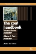
All UCG module configurations are similar, in that they require a minimum of two process points linked within the coal seam: (i) one to inject the gasifying agents and start ignition (injection point); (ii) the other to recover the syngas produced (production point). It is between these two points that a competent gas circuit must be constructed by increasing the coal permeability in a process called ‘linking.’ The configuration of a linked injection point and production point is known as a UCG module (Fig. 8.1a).
8.1 A-F. Schematic diagrams showing: (a) the injection point, production point and in-seam linking; (b) the LVW configurations; (c) the ELVW configuration; (d) the L-CRIP configuration; (f) the P-CRIP configuration; and (e) the SDB configuration.
There are currently three generic types of module configuration: the linked vertical well (LVW) method; the controlled retracting injection point (CRIP) method; and the steeply dipping bed (SDB) method. Other approaches, such as the Chinese long tunnel method (e.g. see discussions by Creedy et al. (2004) and Couch (2009)), see also Li et al. (2007)) and the so-called ‘super daisy shaft’ (e.g. Palarski (2007) and Moncarz (2008)), are not described here.
The LVW method is the oldest of the three generic methods and was developed during a major phase of development in the former USSR. Variants of the LVW method are still used today, most notably at the longest continuously running UCG facility in the world at Angren, Uzbekistan.
Linked vertical wells
There are two types of LVW configurations that have been tested up to now: (i) the standard LVW method; and (ii) the enhanced linked vertical well (ELVW) method. In the LVW configuration, both vertical wells are linked in-seam (Fig. 8.1b) by a number of possible techniques such as reverse-combustion and forward-combustion (e.g. Blindermann et al., 2008), electrolinking and hydro-fracking (see Couch, 2009). The LVW configuration was used extensively during the Russian UCG experiments and in older trials in the West and is still used in the 2010s by at least one UCG company for shallow UCG projects.
The ELVW concept, first tested during the RM1 trial (see Cena et al., 1988), links both vertical wells via a third deviated in-seam borehole (Fig. 8.1c). This technique is thought to have been used in the early phases of Australian and South African projects.
Controlled retracting injection point (CRIP)
The CRIP method was first developed during a major R & D phase in 1980s in the USA (e.g. Hill and Shannon, 1981), and has been further developed during trials in Spain (1990s), Australia (late 1990s to present) and now in Alberta, Canada (late 2000s to the present).
Two different CRIP configurations have been tested up to now: (i) the linear CRIP (L-CRIP) and (ii) the parallel CRIP (P-CRIP). In the L-CRIP configuration (e.g. see UGE (1999) and Creedy et al. (2004)), both process points are linked by one in-seam deviated injection well (Fig. 8.1d). This technique was used at 600 m depth in the first European UCG project, El Tremedal, Spain and is currently being used at 1400 m depth in Alberta, Canada.
In the P-CRIP configuration (see Cena et al. (1988) and discussions in Couch (2009)), both process wells are drilled in-seam parallel to each other. Once the in-seam section has reached a pre-determined length (typically > 500 m in the recent Australian UCG trials) the two process wells are deviated and made to converge towards a third borehole drilled vertically. The third well is used to ignite the coal at the start of operations (Fig. 8.1e). This technique was first tested during the Tono 1 and Rocky Mountain 1 trials in the USA, and is currently being used and proposed by different companies in Australia and Hungary.
UCG in steeply dipping beds (SDB)
As the name suggests, this configuration is used when gasifying coal in SDBs, as shown in Fig. 8.1 f. This technique, used in early trials in Russia and Morocco, was further developed in the USA at trials in Rawlins, Wyoming from 1980–90, with some considerable success (see discussion in Burton et al. (2006) and Couch (2009)). The SDB configuration is arguably the most efficient UCG configuration currently available, but its application is highly dependent on coal seam geology, i.e. coal seam dip angle of greater than 60°.
Which configuration is best?
Previous trials have shown that all the available configurations can be successfully deployed for UCG, but that CRIP configurations are generally more efficient than LVWs (e.g. Cena et al., 1988). It should be noted, however, that data from modern LVWs and CRIPs are not available to make a more up to date comparison than that in Cena et al. (1988).
Despite the apparent lower efficiency, LVW configurations are perhaps better suited to shallow UCG (< 300 m), whereas the CRIP configurations (especially the L-CRIP) work more efficiently for coal at greater depths (typically > 300 m). The LVW configurations are more suitable for shallower coal seams because of reduced drilling and borehole completion costs compared with CRIP configurations. A shortcoming with the LVW configuration, however, is that it relies on enhancing natural permeability to complete the linking. As natural permeability generally decreases with increasing depth, there comes a point at which it is not possible to complete the link between process points, and so other techniques, such as directional drilling, have to be employed.
An additional issue with LVW (and ELVW) is the ‘overriding effect’ whereby the injection point migrates upwards in the coal seam over time. This can result in gasification progressing across the top of the coal seam, leaving the coal at the base of the seam in place, adversely affecting efficiencies and consequently impacting UCG economics. Current trends (see below) are highlighting the need to gasify at intermediate or great depths (e.g. Younger 2011). This, together with the requirement to minimise the overriding effect, is expected to result in the CRIP configurations being used to greater extent in the near future.
8.2.2 Site selection
Perhaps one of the most significant outcomes of previous trials is the importance of selecting the correct site (see discussions in Sury et al. (2004), Burton et al. (2006) and Couch (2009)). Some previous trials, particularly the infamous ‘Hoe Creek’ trials in the USA, resulted in environmental impacts such as surface subsidence and groundwater contamination (e.g. Campbell et al. (1978, 1979) and Wang et al. (1981, 1982a, 1982b)). Although highly unfortunate, trials such as those at Hoe Creek enabled the potential environmental impacts from UCG to be studied and understood. A number of quantitative and semi-quantitative site selection criteria have been published (e.g. Oliva and Dana, 1991; Mastalerz et al., 2011) in order to minimise risk. In general, however, it is now recognised by all responsible UCG operators that a coal seam targeted for UCG should have the following features:
• It should be deep (operators typically state > 300 m, although current UCG projects in Australia are < 300 m) and overlain by consolidated rock with high mechanical strength, low permeability and minimal disturbances (e.g. faulting);
• The target coal seam should be saturated with water and surrounded by rocks that are also saturated with water;
• It should not be located near any groundwater resources, or potential groundwater resources, and be hydraulically sealed so that any contaminated groundwater cannot migrate out of the coal seam.
These features are essentially designed to minimise the risk of environmental impacts. Other criteria are required to ensure that a UCG project is profitable.
UCG economics are closely related to the amount of mass and energy (i.e. coal) that can be recovered per module. The amount recovered per module is a function of the in-seam length (i.e. distance between injection and production points), coal seam thickness, reactor width and coal quality. During UCG operations, there is a limit to how wide a reactor can be developed: initially, cavity growth is radial around the injection point, but once the reactor reaches roof rock the lateral growth (width) component declines and horizontal growth towards the production well dominates (e.g. Luu et al., 2009). As this occurs, gasification efficiency drops as more heat is lost to the surroundings. It is therefore not possible to grow UCG reactors indefinitely. The width a reactor can grow has been found to vary proportionally with coal seam thickness. Thus, the thicker the coal seam, the wider the reactor and the more mass and energy that can be recovered. The in-seam length has a similar effect, with longer in-seam lengths allowing greater volumes of coal to be converted and recovered.
Coal quality refers to the energy density of the coal. The higher the calorific value of a coal, the more energy can be recovered per module and the better the economics. As a rule of thumb, and assuming a reasonable in situ coal calorific value of around 18–20 MJ/kg, coal seam thicknesses greater than 4 m and an in-seam length of 500 m or greater are often economic.
8.2.3 Operating UCG reactors
The third key lesson learnt from previous trials relates to how modules are operated, with three factors being critical:
Reactor pressure
UCG should take place below the groundwater level, in rock fully saturated with water. Saturated conditions are required because large volumes of water are consumed during UCG: roughly one tonne of water is required per tonne of coal in situ gasified (e.g. Blinderman and Fidler, 2003) and because water saturated rocks help to seal the reactor ensuring it remains a ‘closed system’. The water, however, will only ensure a closed system if the pressure in the cavity is less than the groundwater (or hydrostatic) pressure. If a UCG operator exceeds the hydrostatic pressure, syngas will be forced into the surroundings, where it could cause groundwater contamination as well as impact the project economics. UCG operators therefore carefully monitor pressures in real time to ensure that the reactor pressure never exceeds hydrostatic pressure.
Oxidant injection
As for advanced surface gasifiers, the use of pure oxygen instead of air is now preferred in modern UCG. The main reasons are: (i) an improved caloric value of the syngas produced (from lower than 4 MJ/Nm3 to more than 12 MJ/Nm3), (ii) an improved gasification stability and efficiency (more than 20% increase), and (iii) a reduced volume of injected and produced gases.
Reactor decommissioning
A UCG reactor also requires careful decommissioning to ensure that any remaining contaminants are removed. The ‘clean cavern’ techniques were developed during the RM-1 trial in the USA (e.g. Boysen et al., 1990) to quench the reactor and remove any contaminants. The clean cavern technique involves flushing the cavity with water/steam to quickly reduce the temperature of the coal and stop contaminant formation via coal pyrolysis. The large volumes of water also transport any compounds to the surface for treatment. During this process, the reactor is allowed to vent continuously to ensure that its pressure never exceeds the hydrostatic pressure.
8.3 Impact of new technologies
Of the myriad technology developments that have occurred throughout the history of UCG, four stand out as being key drivers to the recent advances in UCG:
2. seismic investigations (3D seismic);
3. high temperature and acid gas-resistant production well engineering; and
8.3.1 Directional drilling
Advances in directional drilling, such as measurement while drilling (MWD) and downhole motor (DHM) technologies, have greatly improved the accuracy of drilling in the deep subsurface (see discussion in Couch, 2009). Directional drilling of advanced trajectories, including short radius deviations and multiple ‘lateral’ wells, i.e. sidetracking multiple wells from a single vertical or deviated borehole, are now routine in the CBM and O&G industries. By using other MWD techniques, such as focussed gamma, directional drillers can now drill along the base of the coal seam for well over a kilometre and intercept another borehole with an accuracy in the order of a metre or less. In terms of cost, the routine use of directional drilling in the O&G and CBM industries has greatly reduced its cost, making it an affordable ‘off the peg’ technology for UCG.
8.3.2 Seismic investigation
Recent developments in seismic source generation, such as seismic vibration technology, allow the controlled application of a defined range of high frequency seismic waves to be introduced into the subsurface. These advances, along with improvements in seismic processing from the O&G industry, have now made it possible to produce accurate, high resolution mapping of individual coal seams down to depths of around 2 km. This aids directional drilling, as well as resource assessment, by allowing the driller to anticipate changes in the coal seam orientation and maintain the borehole in the correct position.
8.3.3 Production well engineering
UCG modules now utilise highly engineered borehole completions, requiring the use of new high specification alloys and precision manufactured components for both the wells and wellheads. These advances have been made possible by advances made in the sour natural gas production industry and the geothermal energy industry.
8.3.4 In situ monitoring
New downhole monitoring technologies allowing hitherto unprecedented measurement of the environment around a UCG reactor have also been developed by the O&G industry. Technologies such as optical time domain reflectometry, and distributed temperature measurement via fibre optic cables, allow accurate high resolution in situ monitoring of position, temperature and pressure profiles. Other technologies, such as microgravimetric and microseismic methods, allow the UCG reactor to be monitored from the surface while others, such as gas tracer tests, allow the volume of the reactor to be predicted in real time.
8.4 Current trends
UCG is now emerging from an R&D industry into a commercial reality. Much of the current activities are consequently geared towards monetising coal resources via UCG and syngas products. The first phase of this has been to demonstrate that the syngas can either be converted into a valuable product, such as liquid fuels, or used to generate electricity. For example, Linc Energy Ltd has been producing small quantities of liquid fuels from its Fischer-Tropsch facility in Queensland, Australia, for many years. Three other UCG operators have been successfully generating electricity: Carbon Energy Ltd has produced electricity via the use of gas engines at its facility, also in Queensland; Eskom, a South African electricity public utility, began co-firing syngas in its Majuba plant coal-fired boilers in 2007 and is now planning a 100–140 megawatt (MWe) open cycle gas turbine (OCGT) – UCG demonstration plant; and the Linc Energy majority-owned Yerostigaz, project, Angren, Uzbekistan, has been providing syngas to a coal-fired power plant since 1961.
The second phase of commercialisation involves increasing syngas output. This is achieved by the simultaneous operation of multiple modules comprising a UCG ‘Panel’. Given the modular nature of UCG, the near future will see outputs further increased along with the application of new technologies to exploit the syngas more efficiently.
As the commercial projects develop, additional onsite plants are being constructed to carry out the necessary by-product treatment and/or recovery. For example, previously in trials such as Linc Energy’s Chinchilla facility in Queensland, waste water (known as ‘greywater’) associated with UCG was trucked offsite for treatment. This is required because greywater contains a range of heavy hydrocarbons (e.g. phenols), metals and other potentially contaminative compounds such as ammonia. As offsite grey-water treatment is a relatively expensive process, UCG operators are now building water treatment facilities onsite. In addition to saving costs, onsite treatment facilities also offer the opportunity to recycle the water and recover the heavy hydrocarbons for sale, providing a potential additional revenue stream.
One exciting syngas exploitation technology is oxycombustion, where syngas is burnt in pure oxygen to generate electricity. There are two advantages of this technology for UCG syngas produced via pure oxygen injection: first, the system is easily adaptable to changes in syngas composition; second, the exhaust gases of the oxycombustion are essentially water and carbon dioxide, and thus a relatively high purity carbon dioxide stream can be captured by condensing the wastewater out. Furthermore, the wastewater will not require significant treatment as the tar by products often associated with gasification greywater are combusted in the oxycombuster.
Carbon dioxide emissions will remain an important factor for UCG in the twenty-first century, as global efforts to reduce greenhouse gas concentrations will limit the amount of the gas that can be emitted without incurring large penalties or associated costs. The UCG industry is currently adapting to this by investigating the potential for carbon capture and storage (CCS) and re-use of carbon dioxide via processes such as enhanced oil recovery (EOR), as is currently being developed by the Swan Hills project in Alberta, Canada. Other synergies of UCG with CCS are also being investigated, including the common spatial coincidence of deep coal seams and potential CCS options (e.g. deep saline aquifers or depleted gas reservoirs) as well as the possibility of injecting carbon dioxide into the spent UCG reactors (e.g. Friedmann et al., 2009; Younger, 2011).
8.5 Conclusion and future trends
The continued advance of UCG into a major global energy industry will bring about attendant changes in areas outside the immediate technical sphere of UCG. Currently, explicit regulations and/or licensing regimes for UCG are few and far between, restricted to a small number of countries including Canada, the UK, the USA and Australia. Currently, regulators around the world are beginning to adapt their regulatory and licensing regimes to allow UCG to take place. This will continue as the number of UCG projects grow and encourage the further development of UCG.
Other important changes that will have important positive effects on UCG include the development of an industry-wide standard for UCG resource assessment. The industry trade association, the Underground Coal Gasification Association (UCGA), is currently spearheading efforts to develop a new formal resource assessment method. Once developed, the new method will free UCG operators from relying on methods not specifically designed for UCG, such as the Joint Ore Reserve Committee (JORC) code and other codes developed for mining (e.g. the United Nations International Framework Classification for Reserves/Resources) or the O&G industry (e.g. the Petroleum Reserves Management System (PRMS)). This will aid new investment in UCG by enabling investors to know how well a potential reserve has been characterised and, consequently, its potential value as far as UCG is concerned.
As more UCG projects come online and the existing projects continue on the path to commercialisation, the available technologies and expertise will continue to develop. It is also expected that large multinational companies will bring their expertise to UCG as the industry evolves. This, combined with economies of scale for important UCG components, such as high specification alloy tubing and casing, will act to further improve UCG to the status of a mature energy technology. The existence of billions of tonnes of coal around the world that is not currently economic to exploit represents a tremendous opportunity for UCG to contribute to the world’s energy mix.
8.6 References
Ahner, P.F., Bencini, J.F., Bloomstran, M.A., Rawlins test 2 data analysis Prepared for Eighth Underground Coal Conversion symposiumGulf Research & Development Company. Colorado: Keystone, 1982. [August, 1982.].
Beath, A., Davis, B. UCG history. Underground Coal Gasification Workshop, United States–India Energy Dialogue, Coal Working Group, 12–15 November 2006, Kolkata, India, PowerPoint presentation, 41 http://fossil.energy.gov/international/Publications/ucg_1106_history.pdf, 2006. [URL. Available from].
Blinderman, M.S., Fidler, S., Groundwater at the Underground Coal Gasification Site at Chinchilla, Australia. Water in Mining Conference Brisbane, Queensland, Australia, 2003:13–15. [October 2003].
Blindermann, M.S., Saulovb, D.N., Klimenko, A.Y. Forward and reverse combustion linking in underground coal gasification. Energy. 2008; 33:446–454.
Boysen, J.E., Covell, J.R., Sullivan, S., Rocky Mountain 1 Underground Coal Gasification Test, Hanna, WY – Results from Venting, Flushing, and Cooling of the Rocky Mountain 1 UCG Cavities GRI Publication No. 90/0156, 1990. [Chicago, IL.].
Burton, E., Friedmann, J., Upadhye, R. Best Practices in UCG. Lawrence Livermore National Laboratory; 2006.
Campbell, J.H., Pellizzari, E., Santor, S. Results of a Groundwater Quality Study Near an Underground Coal Gasification Experiment (Hoe Creek I). Lawrence Livermore National Laboratory, Livermore, CA.. UCRL-52405, 1978.
Campbell, J.H., Wang, F.T., Mead, S.W., Busby, J.F. Groundwater quality near an underground coal gasification experiment. J. Hydrology. 1979; 44:241–266.
Cena, R.J., Britten, J.A., Thorness, C.B., Resource Recovery and Cavity Growth during the Rocky Mountain I Field Test 14th UCG Annual Symposium, Chicago, USA, 1988.
Chris Cothran, C., Dewittm, S., Nimocks, B., Underground Coal Gasification (UCG) 2011 Market Assessment. one of the last great untapped reserves of low-cost energy, 2011. [Zeus Intelligence. Zeus Development Corp 2011.].
Couch, G.R. Underground Coal Gasification. International Energy Agency, London: IEA Clean Coal Centre; 2009.
Creedy, D.P., Garner, K., Holloway, S., Jones, N., Ren, T.X., Review of Underground Coal Gasification Technological DTI Report No. COAL R211, DTI/Pub URN 01/1041. Advancements, 2001. [August 2001].
Creedy, D.P., Garner, K., Oakey, J.E., Abbott, D., Edwards, J.S., Ren, T.X., Jie, L., Shuqin, L., Chai, Clean energy from underground coal gasification in China COAL R250 DTI/Pub URN 03/1611. Department of Trade and Industry, London, UK, 2004.
Friedmann, S.J., Upadhye, R., Kong, F.-M. Prospects for underground coal gasification in carbon-constrained world. Energy Procedia. 2009; 1:4551–4557.
Tech Inc, Gas, Viability of UCG in the Deep Coals of the Powder River Basin, Wyoming. Prepared for the Wyoming Business Council and Industry Division State Energy Office. 2007.
Gregg, D.W., Edgard, T.F. Underground coal gasification. AIChE J.. 1978; 24:753–781.
Hill, R.W., Shannon, M.J., The Controlled Retracting Injection Point (CRIP) System 7th Underground Coal Conversion SymposiumA Modified Stream Method for In-situ Coal Gasification. CA, USA: Fallen Leaf Lake, 1981. [8 September 1981].
Klimenko, A.Y. Early ideas in underground coal gasification and their evolution. Energies. 2009; 2:456–476.
Li, Y., Liang, X., Liang, J. An overview of the Chinese UCG Program. Data Sci. J. 2007; 6:S460–S466. [(Supplement].
Luo, Y., Coertzen, M., Dumbl, S.. Seventh International Conference on CFD in the Minerals and Process Industries CSIRO. Comparison of UCG cavity growth with CFD model predictions. Linc Energy Ltd, Brisbane, Queensland 4001, Australia, 2009:9–11. [Melbourne, Australia, 9–11 December 2009.].
Mastalerz, M., Drobniak, A., Parke, M., Rupp, J. Site Evaluation of Subsidence Risk, Hydrology, and Characterization of Indiana Coals for Underground Coal Gasification. Indiana Geological Survey final report for the Centre for Coal Technology Research Energy Centre at Purdue University. Available from http://www.purdue.edu/discoverypark/energy/CCTR/SiteEval-IGS_March2011.php, 2011.
Moncarz, P.D. Underground Coal Processing. Polish – US Made Radical Energy Solution Technologies. Pilot Plant in Rybnik. Presentation for: Clean Coal Technology Conference, Krakow/Katowice, Poland. http://www.kpk.gov.pl/pliki/8263/Piotr%20Moncarz.pdf, 2008. [17–18 March, 2008.].
Oliva, R.L., Dana, G.F.P., Underground coal gasificationPeters D.C., ed. In Geology in Coal Resource Utilisation, 1991. [Techbooks. ISBN 1-878907-22-0.].
Olness, D., Gregg, D.W. The historical development of underground coal gasification. Livermore, CA: Lawrence Livermore National Laboratory; 1977. [UCRL-52283.].
Palarski, J. Polish activities in underground coal gasification. Presentation for Society of Mining Professors, 18th annual general meeting. Belgrade, Jun 2007. Available from http://www.mineprofs.org/info/research/SOMP-07-Research-Palarski.pdf, 2007.
Sury, M., White, M., Kirton, J., Carr, P., Woodbridge, R., Mostade, M., Chappell, R., Hartwell, D., Hunt, D., Rendell, N., Review of Environmental Issues of Underground Coal Gasification – Best Practice Guide Report No. COAL R273 DTI/Pub URN 04/1881, 2004. [November 2004].
The Oil Drum. The Future of Cheap Energy: Underground Coal Gasification. Posted by Rembrant on 3 August 2011 http://www.theoildrum.com/node/8184, 2011. [Available from].
UGE, Underground Coal Gasification – First trial in the framework of a community collaboration Final Summary Report, 1999. [July 1999].
Walter, K. Fire in the hole. Lawrence Livermore National Laboratory. ST&R April 2007 http://www.purdue.edu/discoverypark/energy/assets/pdfs/cctr/BestPracticesinUCG-draft.pdf, 2007. [Available from].
Wang, F.T., Mead, S.W., Stuermer, D.H. Groundwater contamination near the Hoe Creek UCG experiments. Livermore, CA: Lawrence Livermore National Laboratory; 1981. [UCRL-85880].
Wang, F.T., Mead, S.W., Stuermer, D.H. Mechanisms for Groundwater Contamination by UCG – Preliminary Conclusions from the Hoe Creek Site. Livermore, CA: Lawrence Livermore National Laboratory; 1982. [UCRL-88012.].
Wang, F.T., Mead, S.W., Stuermer, D.H. Mechanisms for groundwater contamination by UCG – preliminary conclusions from the Hoe Creek study. Proceedings of the Eighth Underground Coal Conversion Symposium; 1982.
Energy Council, World Regency House 1–4 Warwick Street, London W1B 5LT United Kingdom. 2007 Survey of Energy Resources. World Energy Council, London, UK, 2007. [ISBN: 0 946121 26 5].
Younger, P.L. Hydrogeological and Geomechanical Aspects of Underground Coal Gasification and its Direct Coupling to Carbon Capture and Storage. Five Quarter Publications. Mine Water Environment http://www.five-quarter.com/images/Hydrogeological_Geomechanical_Aspects_of_UCG-CCS.pdf, 2011. [DOI 10.1007/s10230-011- 0145–5. Available from].