
Post-treatment of coal
Abstract:
In this chapter, post-treatment of coal is defined as those black coal processing applications that may be deployed to add value following the completion of conventional mining and coal preparation activities. It is the application of the processes that renders them applicable as subject matter for this chapter, rather than their inherent functionalities. However, a clear delineation does not exist and there may be, at times, overlap of material found in this chapter with that found elsewhere in this book. Following a brief introduction, a section on fine coal liberation is given. This includes the importance of knowing, and ways of estimating, the extent of liberation of a given coal using comminution, tree flotation and microscopy methods. Sections are presented on ways to effect liberation at fine sizes. Various types of milling processes are described. Descriptions of ammonia and methanol/sodium hydroxide chemical comminution procedures then follow. A section is provided which describes various applicable physical beneficiation technologies that involve froth flotation-based, magnetic and electrical separations. Chemical cleaning processes are then described, followed by a brief discussion of relevant new dewatering and drying technologies. A section is included on the effective treatment of high clay content coals. The chapter concludes with a description of some other post conventional coal cleaning technologies, including oil agglomeration, pelletising and briquetting of fine coal, as well as an emerging process to use coal as a diesel replacement.
15.1 Introduction
15.1.1 Definition
In this chapter post-treatment of coal is defined as those black coal processing applications that may be deployed following the completion of conventional mining and coal preparation activities. It is the application of the processes that renders them applicable to this chapter, rather than their inherent functionalities.
Such a definition therefore embraces the rather nebulous nature latent in the title of this chapter, and the processes included, in most cases, do not have exclusive application to coal post-treatment applications. They can, like most coal beneficiation processes, be applied anywhere in the coal treatment chain. Indeed, some of the post-treatment processes described in this chapter can be used as a substitute for or adjunct to what are currently regarded as conventional coal preparation processes.
15.1.2 Need for post-treatment
The need for post-treatment arises in those situations when mine site or coal preparation plant product cannot meet the physical and/or chemical requirements for final utilisation in an economical way.
A common need for post-treatment of coal is size reduction, also known as comminution (Vince, 2009a). Whilst the metallurgical and thermal utilisation of coal almost invariably is in the form of very fine powder, only lumpy material (e.g. 150–50 mm top size) is commonly supplied from mine site operations.
The presence of fine coal increases moisture carrying capacity and can make preparation and handling very difficult and expensive. In almost all coal production operations it is important to minimise size degradation. It is imperative to keep the coal as coarse as practicable for as long as possible in the production chain. For example, in many coal-fired power station operations, the pulveriser unit includes an in-built air sweeping mechanism in which nascent pulverised coal passes directly into the combustion chamber (Schumacher, 2010). Similar use of nascent milled coal often occurs with hammermills in coke oven plants, and pulverisers in blast furnace applications.
There are also a large number of lower quality coal deposits around the world. It may be difficult to economically separate products that comply with market requirements from these coals using conventional coal preparation methods in isolation. In such instances, alternative coal processing methods are sometimes an option for achieving a commercially viable operation. The processing methods applicable in such cases may also be termed post-treatment processes. As an example, for some lower quality coal deposits, sufficient liberation can require generation of fine particles. Once generated, these fine particles may need to be beneficiated, dewatered, dried and size enlarged.
15.1.3 Coal quality characteristics
The coal quality characteristics that are imparted during the coal formation processes are discussed in an earlier chapter in this book. These are from an overall coal processing perspective. From a post-treatment of coal perspective, the most important are:
Natural size distribution
To a large extent, this determines the proportion of fines in the raw coal. If they are too high, difficulties may arise with preparation, handleability and contractual compliance.
Liberation size
Liberation size is that size at which sufficiently distinct particles of desirable coal and undesirable particles predominate, as opposed to existing as conglomerate particles. The presence of distinct desirable and undesirable particles permits separation to be effected with appropriate technologies.
If the liberation size is sufficiently large (say 10 mm or larger) then a conventional coal preparation plant may be applicable. However, if the liberation size is small (say 1 mm or smaller) then the commercial viability of mining the resource may be compromised without a favourable coal response to alternative processing technologies. Some of the more important alternative processing technologies are presented later in this chapter.
Maceral composition and rank (reflectance)
The maceral composition and rank (reflectance) of the coal has a major impact on its suitability to meet particular market segment specifications. If metallurgical (coking and PCI) coal market specifications can be met, a higher price may be achievable for the product coal.
The first two of these three points pose a dilemma in that:
1. Low fines levels in shipments are required for moisture, specific heat content and handleability reasons.
2. High fines levels in run-of-mine coal are frequently unavoidable when the objective is to maximise extraction rate, recovery and resource utilisation.
Many coal post-treatments have been focussed on addressing this dilemma by increasing the effective size of fine coal particles by some kind of aggregation technology. The development of such technologies is aimed at providing an adjunct process to compensate for any upstream raw coal size reduction necessary to increase resource recovery. This is an example of an area targeted by coal post-treatments.
15.2 Estimating required liberation size
Physical cleaning requires the ash forming components of the raw coal to be sufficiently liberated from the coal. The liberation size is a fundamental characteristic of the coal type.
15.2.1 Comminution
The liberation size is conventionally derived by quantifying the size reduction necessary to reduce gangue-coal particle conglomerates such that individual low ash value grains prevail. This ash value would be expected to reduce asymptotically to a minimum value with the extent of size reduction.
Figure 15.1 shows the minimum ash levels estimated for a NSW coal using literature data (Keast-Jones and Smitham, 1988) for coal preparation plant rejects following various degrees of grinding. For the coal considered here, the minimum ash value is around 3%, and obtained by crushing to a top size of around 2 mm.

15.1 Minimum ash values estimation by crushing washing coal preparation plant rejects (Keast-Jones and Smitham, 1988).
15.2.2 Tree flotation approach
Tree flotation (Nicol, 2001) is a technique, particularly applicable to hydrophobic coals, which can be used to estimate the ash value of the most liberated coal particles present and relate this to particle-size distribution in a given sample. For any given properly constructed tree flotation curve, the lowest ash value (Alowest) of any fraction is represented by the datum point providing the lowest cumulative ash value. By determining the Alowest value as the extent of grinding is increased, an estimate can be made of the amount of grinding required to achieve liberation.
Figure 15.2a shows tree flotation data for a blend of Newcastle (NSW) coals with various degrees of grinding. Starting from the ‘natural’ size distribution, grinding to finer sizes causes the Alowest value to reduce. Figure 15.2b shows similar data for a single coal seam (Wambo, Hunter Valley).

15.2 (a) Tree flotation data for blend of Newcastle measures coals following various amounts of grinding (Keast-Jones and Smitham, 1988). (b) Tree flotation data for Wambo seam coal following various amounts of grinding (Keast-Jones and Smitham, 1988).
Alowest data for both cases are plotted on Fig. 15.3, which indicates:
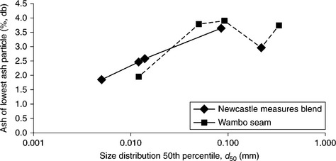
• For the blended material, the minimum Alowest value is estimated as 2.0% with a 50% passing size (d50) of around 5 μm.
• For the single seam material, the minimum Alowest value is estimated as 1.9% with a 50% passing size (d50) of around 12 μm.
When it is important to determine the extent of grinding required, such testing would be recommended for each case in point.
15.2.3 Evaluation by electron microscope and mineral liberation analysis
Quantitative evaluation of minerals by scanning electron microscope (QEMSEM) and mineral liberation analysis (MLA) are automated analytical systems provided by FEI Natural Resources to estimate detailed mineralogical information. Although they are specifically designed for metalliferous minerals, they can be used to determine the size of minerals present in the coal matrix (Fandrich et al., 2007).
15.2.4 Coal grain analysis
Coal grain analysis (CGA) can be used to quantify liberation size (Ofori et al., 2004; O’Brien et al., 2011). The method determines the number of mineral inclusions within particles and is a good complement to tree flotation and washability by size information.
15.2.5 Implications of determining liberation size
The most important implication of determining the liberation size is the impact of grind size on the yield/ash curve. For the general case of a poor quality coal, it may be necessary to reduce particle sizes to small levels to achieve an adequate degree of liberation. If re-processing fine coal tailings is considered, it may also be necessary to grind fine coal.
15.3 Milling coal for liberation
15.3.1 Pulverisation
Grinding coal to fine sizes, conventionally undertaken dry for power plant use, is commonly achieved with dedicated pulveriser units. Such units are typically air-swept and can be considered to use around 1.5% of the electricity the power station generates. A good rule of thumb is that the energy used in power station pulverisers is 7.5–8.0 kWh/t of black coal on an as-received basis. The figures do, however, vary greatly from case to case (Schumacher, 2012).
A typical air-swept coal pulverising unit would reduce 50 mm top size coal to around 75 μm.
Coal pulveriser types may be classified as:
Grinding of coal in a wet milling application, while not being a common practice, has been undertaken for coal conversion processes such as Integrated Coal Gasification Combined Cycle (ICGCC) plants (Schumacher, 2012) and typically utilises tumbling mills; for example, the Polk Power plant in Florida (Hornick, 2002) uses rod mills. A typical Rod Mill is shown by Fig. 15.4.

15.3.2 Micronisation
Equipment used for micronising coal in either moist or slurry form is usually a high energy consumer, and milling equipment can be high capital and maintenance cost items. Grinding to micron size is a non-linear process in which disproportionately more energy is required, the finer the progeny particles become. There also exists a critical size below which further size reduction becomes extremely difficult.
MicroEnergy Systems Inc. (MSI) Micronization Mill
MicroEnergy Systems Inc. have patented and commercialised the MSI Micronization Mill technology which, in essence, consists of a motor and a vertically orientated housing containing a rotor shaft (see Fig. 15.5). Unlike more conventional pulveriser technologies which grind coal between rapidly rotating hard surfaces, the MSI unit has no metal-to-metal contact. Similar to distillation column tray technology that is ubiquitous in oil refineries, the MSI housing contains a number of stages through which particles of ever-decreasing size pass. The control stages of rotor plate and impactor assemblies are mounted on a common rotating shaft. The micronisation process occurs by lump-sized coal and air entering from different ports located at the top of the unit. Pneumatic air flow is effected by an extraction fan located at the base, which also ejects the micronised coal product-laden air into the combustion furnace.
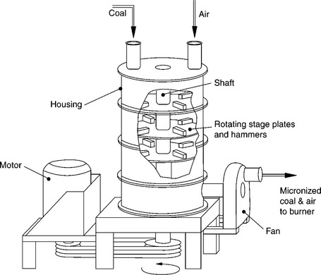
Coal particle breakage occurs when contacted by a series of rapidly rotating impactors that effect comminution by a combination of particle–particle and particle–wall collisions. The external booster fan mounted on the mill outlet maintains a heavy downward flow bias. As particle size reduces at each controlled stage, the down flow air entrains and progressively drags particles to each lower stage level to facilitate further size reduction. The design is such that a given size reduction ratio is promoted at each stage and is therefore consistent with achieving efficient size reduction (Vince, 2009a).
A unique classification process at the lower mill stages traps and restricts efflux of oversized particles until they attain the desired size reduction. At the lowest stage, particles achieve micron size and flow out in an entrained mixture of air and micronised coal, which is then piped directly to a burner for combustion.
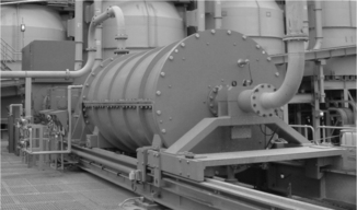
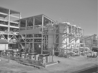
It is well suited to comminuting lump-sized coal to produce particles with mean diameter size of about 15 μm, and Fig. 15.6 shows an industrial installation of the technology in the USA.

IsaMill™
The IsaMill™ milling technology is a large-scale commercial high-speed stirred mill that is currently under development for coal micronising applications. The technology achieves very high energy efficiencies by using small milling balls in a high intensity configuration (> 300 kWmm−3). It is claimed that the technology (Fig. 15.7) can produce coal with 90% of the particles less than 20 μm.
IsaMill™ technology is receiving serious consideration as part of a CSIRO investigation into preparing micronised coal for coal/water fuel in a diesel engine to deliver base-load power (see Section 15.10.1).
Details of the size of units available can be obtained from Xstrata Technology. As a very rough guide, grinding 200 t/h of coal is estimated to require a 3 m diameter unit (1120 kW).
It is recommended that a sample of material is sent to the equipment manufacturer for testing, and there is anecdotal evidence that the IsaMill can be scaled up with reasonable confidence.
High pressure grinding rolls
High pressure grinding rolls (HPGR) achieve grinding by breaking particles under compression in a packed particle bed. This is in contrast to the direct nipping mechanism deployed by conventional crushing rolls.
Fuerstenau et al. (1995) indicate that a laboratory scale HPGR mill invariably produced an agglomerated material when fed sample of Pittsburgh No. 8 bituminous coal. It was identified that the briquette-like HPGR mill product could be dispersed using a small secondary ball mill. A photograph of a KHD unit is shown by Fig. 15.8.
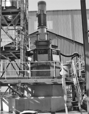
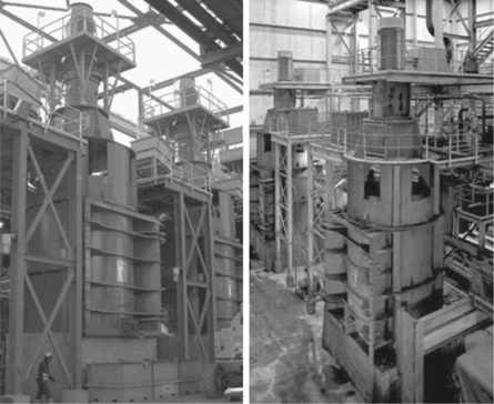
Szego Mill
The Szego Mill (see Figs 15.9 and 15.10) uses a proprietary roller mill technology developed over the past 30 years by General Comminution Inc. and the University of Toronto. It is claimed that the mill has very high specific capacity and low energy consumption values, up to 40 times larger than for tumbling mills. It can operate dry with air sweeping, or wet by accepting process slurries and thick pastes.
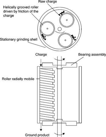
15.9 Schematic arrangement of Szego Mill. (Source: After Trass, 1980.)
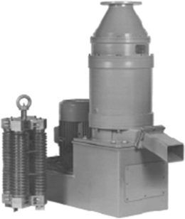
It is claimed that fine particle sizes of 1–10 μm can be achieved.
The Szego Mill (Trass, 1980) also has the capability to undertake simultaneous grinding and beneficiation for the production of coal-slurry fuels. In this application, oil is used; mineral matter is liberated from coal and enters the water phase, and coal is reduced in size and forms agglomerates in the oil phase. The oil phase is then separated from the water phase, resulting in a stable coal-slurry fuel.
Metso stirred media detritor (SMD) mill
The Metso SMD mill is a low-speed mill with stirrer tip speed typically set at 3 m/s and typically grinding to 80% passing 15 μm. SMD mill feed size is typically 150 μm and so pre-comminution is required. The SMD mill is shown in Fig. 15.11.
Metso VERTIMILL®
The Metso Vertimill (see Fig. 15.12) is capable of receiving 6 mm particles and grinding to around 20 μm.
FLSmidth VXPMill (Knelson-Deswik Mill)
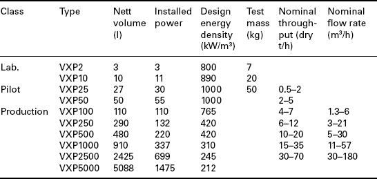
This stirred mill unit (Fig. 15.13; Table 15.1) claims to reduce the d50 from around 300 μm to less than 10 μm. Some test work (Rahal et al., 2011) has also been reported for one such unit.

15.4 Chemically treating raw coal for liberation
Chemical comminution involves the use of chemicals to effect a size reduction in coal particles.
15.4.1 Ammonia-based chemical comminution processes
A high pressure size reduction process that involves exposure of raw coal to specific low molar mass chemicals has been described by Weiss et al. (1982). This process exploits the fact that some chemicals effect coal particle fracture such that:
• Boundaries between maceral and mineral matter components strongly influence the breakage. This is particularly true when the mineral is iron pyrites.
• A bi-modal progeny particle-size distribution is promoted that tends to minimise fines production.
Important attributes of these chemicals are that they are relatively inexpensive and recoverable.
In one process, conventional comminution is required to reduce the top size to 38 mm. The following major steps are then deployed:
Treatment with ammonia in its gaseous, liquid or aqueous form.
Ammonia removal from coal by washing with water.

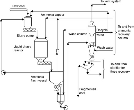
15.14 Proposed batch chemical comminution process using ammonia vapour. (Source: After Weiss et al., 1982.)
Ammonia recovery from wash water for recycling by distillation and compression.
Delivery of comminuted coal to a physical processing unit.
While not commercialised, three process variants were proposed:
Processes using gaseous ammonia
(a) Batch process (see Fig. 15.14)
The batch process proposed involved using gaseous ammonia at ambient temperature and operating at 120 psi (830 kPa). To operate a feed rate of 1136 t/h, the process was estimated to require ten reactor tanks, each 7.6 m in diameter and 18.3 m high. With raw coal moisture of around 6%, the recirculating ammonia required was estimated to be 91 tonnes. Ammonia losses were expected to be very low. A 50 °C operating temperature rise was also anticipated due to the heat of ammonia solution. The cycle time of the process was estimated to be 5 h.
(b) Continuous process (see Fig. 15.15)
The continuous process proposed involved using pressure lock reactors with gaseous ammonia. In this flow sheet, the comminution reactor is charged using two parallel feed hoppers. The product from the reactor is discharged to a flash vessel where most of the ammonia is separated and passed to the ammonia recycle section. The solids from the flash vessel are then slurried with recycled water and pumped counter-current to the hot water wash column. An aqueous ammonia stream from the wash column is sent to an ammonia recovery column, and the coal product stream is screened and sent to a conventional coal preparation plant for separation of impurities.
Continuous process using aqueous ammonia
In this process, shown by Fig. 15.16, coal is fed continuously to the reactor as slurry, and discharged to the flash vessel, where most of the ammonia is separated for recycling. The coal from the flash vessel is slurried in a mixing tank and pumped to a wash column for treatment similar to that described for the continuous ammonia vapour process.
15.16 Proposed continuous chemical comminution process using ammonia liquid. (Source: After Weiss et al., 1982.)

15.15 Proposed continuous chemical comminution process using ammonia vapour. (Source: After Weiss et al., 1982.)
15.4.2 In situ chemical comminution
In situ chemical comminution (Mamaghani et al., 1987) has also been proposed, in which reactive chemicals (methanol and aqueous sodium hydroxide) are used to comminute raw coal in the ground. Further information can be found elsewhere in this volume.
15.5 Beneficiation
Generally speaking, particles greater than around 1.5 mm are relatively easy to treat, with the degree of difficulty increasing rapidly as particles become finer than 0.25 mm.
15.5.1 Niche process designs
A conventional coal preparation plant is typically large and complex. However, in some cases the degree of complexity and local environmental impact can be minimised by resource and market characteristics.
With a high quality resource, there are situations where all raw coal can be sent to market without processing.1 This has major benefits that include:
There are also niche applications in which processing is required to maximise the value of the resource, but no waste is produced. This may involve conventional processing to separate a high value premium product, typically a metallurgical coal. The rejects of such processing may be of sufficiently high quality that a thermal market may be found for it in its entirety.
Selection of appropriate beneficiation methods depends to a large extent on the size of particles to be treated. This is shown diagrammatically by Fig. 15.17.
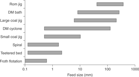
15.17 Particle size ranges separated by the most commonly used processes (Vince, 2009b).
15.5.2 Flotation options
The flotation options available for post-treatment of coal include mechanically agitated flotation machines, Jameson Cells, and a variety of column flotation cells. A new supersonic flotation machine, based on Jameson Cell concepts, is also becoming available.
The proportions of installed flotation capacity have changed dramatically over the last 30 years or so as the newer Jameson Cell and column flotation technologies have gained broad industrial acceptance.
Mechanically agitated flotation machines
Such machines have been available for many years, with continual design improvements implemented as they are identified. Manufacturers include Denver, Wemco, Outokumpu, Humboldt Wedag, and FLSmidth. The biggest advance in mechanically agitated cells has been unit capacity from increases in cell size.
Mechanically agitated flotation cells characteristically have shallow froths and low frother reagent requirements. They also produce froths that are prone to contamination with undesirable material present in the bulk slurry due to poor froth drainage.
Jameson Cell flotation machines
Jameson Cell flotation units (see Fig. 15.18) have great appeal to the Australian coal industry. They have no moving parts and rely on the venturi effect to entrain air into the feed line to effect the flotation separation with consistently fine bubbles. They are also normally operated with a tailings recycle flow set at around 30%. Operationally, they also produce thick froth layers (0.3–1.0 m) and require unconventionally high frother dosages (15–20 ppm) to stabilise the froth. The thick froth layer has the great advantage of promoting drainage of entrained bulk slurry from the froth to reduce contamination. Provision of wash water to the froth also aids the production of lower concentrate ash levels.
Column flotation machines
Column flotation machines common in the Australian coal preparation industry include the Microcel unit (Fig. 15.19) invented by Professor Roe- Hoan Yoon at Virginia Polytechnic and State University. Such a unit utilises in-line mixers to contact air with reagent laden feed slurry to achieve the separation. Once again, the tailings are usually recycled and a deep froth with wash water addition used to produce remarkably low froth concentrate ash levels.
Supersonic column flotation machine
This unit is shown diagrammatically by Fig. 15.20 (Jameson, 2010) and is specifically designed to produce very fine bubbles for application to slurries containing ultrafine coal particles. It is similar to the Jameson Cell. Important differences are that air is added under pressure and a shock wave is induced at the downcomer exit orifice so as to promote very fine bubble formation. Once again, high frother dosing would be expected. High frother levels can create frothing issues in non-fines processing circuits, e.g. dense medium circuits that, in most cases, require frother addition rates to be operationally reduced to sub-optimal levels. Ways of overcoming this problem include isolating the flotation and dewatering water circuits from the rest of the plant and installing scavenger flotation units on the frother-starved column flotation circuit tailings.
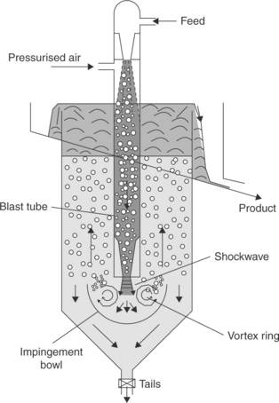
15.20 Schematic representation of supersonic flotation column. (Courtesy Prof. Jameson, 2010.)
Fluidised bed flotation unit
This was devised to promote the recovery (Jameson, 2010) of coarse particles in froth flotation (see Fig. 15.21).

Central Fuel Research Institute (CFRI) improved flotation process
The India-based Central Institute of Mining and Fuel Research have developed a flotation process specifically for beneficiating high ash coking coal fines. The process uses (Haldar, 2005) autogenous vacuum generation to facilitate feed from a conditioning and emulsifying tank as well as tailings recycling.
CFRI oleo flotation process
This process (Haldar, 2005) involves treating raw coal fines in thick slurry form with diesel oil and a fraction of tar oil. Once conditioning is complete, the slurry is diluted and passed to a flotation cell to separate low ash concentrate as oil flocs. In this way, fine coal is first selectively agglomerated before being beneficiated. The partially dewatered concentrate is then combined with coarser wet solids and dewatered to satisfactory moisture levels using a conventional centrifuge. The advantages of such a process include improved recovery of ultrafine coal and lower overall final moistures. This process has been developed to 20 t/h pilot scale.
15.5.3 Magnetic processes
Magnetic processes relate to those in which a magnetic field is applied to the material to be separated. The industrial application of magnetic fields has advanced significantly in recent decades, with highly efficient and effective magnetic separator designs becoming industrially available (Norrgan and Mankosa, 2002).
It is well known that coal is ostensibly unaffected by a magnetic field, with recent literature (Thomas, 2012) indicating its magnetic susceptibility to be very low (0.002). Therefore, magnetic processes are generally only applicable to coal systems where other components have higher magnetic susceptibilities.
Magnetic separation is commonplace in conventional coal preparation plants as a means of recovering magnetite from dilute dense medium process slurries. The separation is relatively straightforward to achieve using conventional wet-drum high gradient magnetic separator technologies, due to the relatively large magnetic susceptibility (0.12–3.07) of magnetite (Taggart, 1953).
With regard to the beneficiation of coal using magnetic processes, use is made of the inherent differences in the weakly magnetic (paramagnetic) mineral matter (clays, quartz, pyrite, and calcite) and the essentially nonmagnetic (diamagnetic) coal material. Exploitation of these differences requires a magnetic field that is much stronger than that provided by conventional wet-drum magnetic separator technologies. Two generic techniques of providing these high magnetic fields have been described in the literature (Liu, 1982a; Osborne, 1988; Nicol, 2001; Norrgran and Mankosa, 2002; Wills, 2007). These are electromagnets and permanent magnets.
Batch electromagnetic processes
Early pilot scale developments in this area have been described (Osborne, 1988). One of these involved placing a porous ferromagnetic material (e.g. ferritic stainless steel wool) in an electrically generated magnetic field housed in an iron enclosure (Oder, 1976), see Fig. 15.22. In this concept, coal is passed in slurry form through the electromagnetically activated steel wool, where the contaminants tend to be retained, allowing relatively clean coal slurry to exit. After a period of operation, the steel wool becomes saturated with contaminant material, and operating effectiveness substantially decreases. It becomes necessary to stop the feed, and, whilst the electromagnetic coils remain energised, flush any residual non-magnetics trapped within the stainless steel wool bed with water. The electromagnetic coils are then de-energised and the non-magnetic material flushed and collected separately.

15.22 Schematic representation of batch electromagnetic high gradient magnetic separation. NB: This machine was developed for use in the kaoline clay industry, not coal. Use in coal would require extensive grinding prior to HGMS treatment. (Source: After Oder, 1976.)
Similar machines have been devised in which the electromagnet is replaced by permanent magnets, but these suffer from the inability to modulate the strength of the magnetic field.
Continuous electromagnetic processes
To overcome the need to stop the batch process intermittently, continuous processes based on the same principles have been invented (Hise et al., 1979, 1981; Oberteuffer and Arvidson, 1979). The essential elements of the design deploy a rotating magnetisable carousel which moves a matrix medium, sequentially, through the following sections:
Integration of magnetic separation with pulverisation milling
Dry cleaning of fine coal has not found general commercial application, for reasons that include lack of methods suited to efficient dry separation and removal of non-combustible minerals generally smaller than 6.3 mm. Modern magnetic technology has evolved to be able to separate ferruginous minerals including iron pyrite, a major source of sulphur in coal, reasonably efficiently in sizes down to nominally 75 μm–0.150 mm (Oder, 2013). A process, known as the MagMill™ process (Oder, 2012) applies modern magnetic technology to dry cleaning of pulverised coal at the point of use, such as coal-fired power plants.
This process combines pulverisation with dry separators, including magnetic separators, to remove mineral contaminants from coal. It is claimed (Oder, 2013) that this is achieved more efficiently and economically than can be done at a wet coal preparation plant. The process has been developed to be installed as a retrofit to existing pulverised-coal-fired power plants and offers new coal combustion or gasification plant designs which may have lower capital and operational costs. It is claimed that the technology has both environmental and operational advantages. As ash forming minerals containing sulphur, and hazardous trace metals such as mercury, arsenic, selenium and others, are removed the cost of postcombustion control, including fly ash disposal and hazardous air pollutant removal, may be significantly reduced. By elective removal of hard and abrasive minerals from the feed coal before they are over ground, deleterious sources of abrasive and erosive wear and of slagging and fouling are removed before the coal enters the combustor. This is vitally important in modern supercritical power plant design, where steam tube tolerances are especially small.
The MagMill™ process removes the hard-to-grind, dense and abrasive components from coal while reducing grinding energy and abrasive wear, and improving the quality of coal by lowering mineral content, sulphur, and hazardous trace metals. This process will work for all coals where the particles to be removed are at least feebly magnetic and are ‘liberated’ or ‘semi-locked’ in the nominal 2.4–150 μm size range. This magnetic separation process has been developed for dry cleaning coal used for power generation by EXPORTech Company, Inc., and is shown diagrammatically by Fig. 15.23.
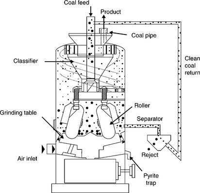
Figure 15.23 indicates (Oder et al., 2008; Oder, 2013) that coal feed falls onto a pulveriser grinding table from above and flows outward as the table rotates beneath large metal tyres which crush the coal as they roll over it. Hot air swirls upward around the circumference of the table and entrains fine coal released during milling upward to the classifier at the top of the mill. Here oversized particles are separated and returned to the grinding table. The concentration of hard and abrasive minerals is significantly greater on the surface of the grinding table than in the feed coal because these minerals require more passes through the grinding zone to reach product specification than does the softer components of the coal. The MagMill™ withdraws a stream of these concentrated minerals from the lower regions of the mill and passes it to a dry separator outside the pulveriser. The separator preferentially recovers low ash, low sulphur material for return to the mill and rejects higher ash, higher sulphur material that would otherwise have gone to the burner. A dry magnetic separator is employed for the separation of iron pyrite and other ferruginous minerals.
A number of large-scale tests have been successfully completed on all coals of all ranks, with the exception of anthracite. While operating at 98% Btu recovery, one set of prototype testing of Powder River Basin (Oder, 2013) achieved:
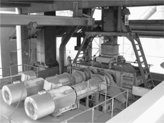
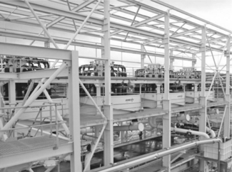
Figure 15.24 shows EXPORTech’s magnetic separators enclosed in a separate structure at a pilot test facility at the DTE Energy Services petroleum coke grinding facility in Vicksburg, MS, USA.
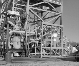
15.24 EXPORTech magnetic separators enclosed in orange structure. (Courtesy EXPORTech Company, Inc.)
The technology has been shown to significantly improve coal grindability and reduce abrasiveness (Oder, 2012).
Pre-treatment for magnetic separation
The effectiveness of magnetic separation can be significantly improved in some cases (Osborne, 1988; Nicol, 2001) by undertaking some form of pretreatment, such as (Osborne, 1988):
An example of chemical pre-treatment is the Magnex process (Kindig and Goens, 1979) in which an oil-based magnetic fluid in colloidal form is selectively absorbed onto the surface of the coal particles. This enhances their magnetic susceptibility, and a schematic representation of such a process is shown by Fig. 15.25 (Nicol, 2001).
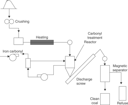
15.25 Schematic representation of Magnex process (Nicol, 2001). (Courtesy Australian Coal Preparation Society.)
Magnetic reagents
An alternative method has also been proposed (Hwang et al., 1992) which involves selective flocculation methods to co-flocculate coal with fine magnetite and has been termed the magnetic reagent technology. Magnetic reagents (Hwang, 1990, 1992) are magnetic minerals with surfactants built on their surface to serve as bridges connecting magnetic materials to other minerals. The application to coal processing involves the suppression of coal particle coating such that non-coal particles are rendered susceptible to magnetic separation. When this has been achieved, significant sulphur level reductions are claimed to be achievable.
15.5.4 Electrical separations
Electrical processes exploit differences in the electrical characteristics of high and low ash components of the raw coal. Such characteristics are dielectric constant, electrical conductivity and work function (Nicol, 2001). Typically, a two-stage process is needed with Stage 1 being the charging up of the particles to be separated, followed by Stage 2 in which the charged mass is subjected to an electrical or magnetic field to effect the separation. Such processes are typically dry.
A number of processes have been described (Osborne, 1988; Nicol 2001) that are applicable to fine coal beneficiation. These are as follows.
Vertical belt separator
This was an experimental electrostatic process device (Nicol, 2001) provided by Advanced Energy Dynamics Inc, and a schematic representation is provided by Fig. 15.26. Coal is separated from mineral matter by exploiting differences in work potential utilising an electric field applied across a vertical open mesh transport belt. When entering the electric field, the different components of the feed acquire different charge polarities, with coal tending to acquire a net negative charge and mineral matter the opposite. A separation then becomes possible, with the mineral matter tending to be attracted to the upward moving section of the belt to be discharged at the top, and coal attracted to the downward moving belt section to be discharged at the base of the unit.
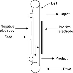
15.26 Schematic representation of Advanced Energy Dynamics Inc Vertical Belt Separator (Nicol, 2001). (Courtesy Australian Coal Preparation Society.)
Horizontal belt separator
This is a device developed by The Pittsburgh Energy Technology Centre (Nicol, 2001) that uses a copper surface to triboelectrically charge ultrafine coal particles, as shown schematically in Fig. 15.27. The charged particles are separated between charged plates held at around 50 kV potential difference. The clean coal particles are attracted and collected from the cathode chamber.
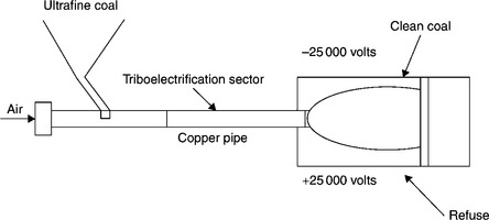
15.27 Schematic representation of The Pittsburgh Energy Technology Centre Triboelectric Separator (Nicol, 2001). (Courtesy Australian Coal Preparation Society.)
Rotary triboelectric separator
A more recent process has been investigated experimentally (Bada et al., 2010) to process South African fine coal, and is shown diagrammatically in Fig. 15.28. In tests the unit was able to reduce the ash of minus 177 μm raw coal by around 15 percentage points.
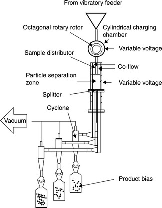
15.28 Schematic representation of triboelectrostatic separator. (Source: After Bada et al., 2010.)
15.6 Chemical cleaning
Chemical cleaning of coal can either leach the contaminants from the coal, leaving a relatively clean solid mass, or leach the coal, leaving a solid mass high in impurities. Such processes utilise alkali, acid or organic solvents as lixiviants. Some chemical methods are effective at removing both organic and pyritic sulphur.
15.6.1 Hydrofluoric acid process
This process is under development at the University of Nottingham (Steel, 2007) and is claimed to require stoichiometric quantities of hydrofluoric acid to effect almost complete removal of ash-forming minerals. The process, shown diagrammatically in Fig. 15.29, is claimed to produce coal with less than 0.1% mineral matter with total recycle of the hydrofluoric acid.

15.29 Schematic representation of HF leaching process. (Source: After Steel, 2007.)
15.6.2 Hypercoal process
The Hypercoal Process was developed to produce ash free coal (Okuyama et al., 2004) using two ring aromatic type chemicals, e.g. methyl-naphthalenes in an elevated temperature extraction process. The process preferentially solubilises the organic material to separate it from the mineral matter before recovering solid organic matter (ultra-low ash coal) by volatising the solvent. The process is shown schematically in Fig. 15.30.

15.30 Schematic diagram of Hypercoal process. (Source: After Okuyama et al., 2004.)
15.6.3 Ultra Clean Coal (UCC) process
This process (Boyd, 2007), shown schematically on Fig. 15.31, involves chemical leaching in a manner similar to the Bayer process for alumina refining. The process involves a number of steps to solubilise and remove the minerals. The dissolved minerals are then precipitated and either disposed of or potentially re-utilised.
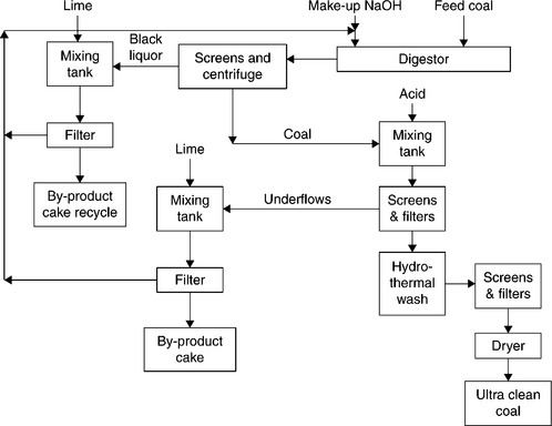
15.31 Schematic representation of Ultra Clean Coal process. (Source: After Boyd, 2007.)
15.6.4 Comparison of Hypercoal and UCC processes
The relative merits of the Hypercoal and UCC processes for chemically cleaning coal have been assessed in relation to the potential to supply electricity in Japan (Cottrell et al., 2004, 2007). For this assessment, the chemically cleaned coals were assumed to be direct fired into a combined cycle gas turbine. It was noted that direct firing of coal into gas turbines was not a mature technology, due to major issues relating to turbine damage from inorganic material present in the coal feed. However, the very low ash levels present in the chemically cleaned coal from these processes opens the door to the direct-fired option.
The major findings from this study were summarised as:
Hypercoal gives a 9% reduction in greenhouse gas emissions compared to a supercritical power station operating on pulverised coal.
Significant (approximately 19–21%) reductions in delivered electricity were reported using either the Hypercoal or UCC material.
The breakeven CO2 penalty at which a liquefied natural gas fuel source would match the delivered cost of electricity for hypercoal and UCC was estimated in 2007 to be $28–38/t CO2.
The cost advantage of using chemically cleaned coal over a conventional supercritical pulverised fuel was almost entirely dependent on avoiding transmission costs by achieving high thermal efficiency in smaller capacity non-centralised power plants. Such a funding, it was noted, would be highly location dependent and estimated assuming high thermal efficiencies and low maintenance costs.
Important unknowns in this assessment were the chemically clean coal production costs.
15.7 Dewatering
Dewatering, in the context of post-treatment of coal, concerns removing water from a coal/water slurry. It is well known that the degree of difficulty of removing water increases as particle size becomes smaller (Leonard, 1991). Many post-treatment processes deal with fine and ultrafine coal dewatering. This is the most difficult size range to remove water from, and what follows is a selection of recent developments in fine and ultrafine coal dewatering.
15.7.1 Flocculant addition tube for screen bowl centrifuges
Due to the very high G-forces generated, screen bowl centrifuges are able to achieve lower product moistures (12–16% TM) due to significantly higher dewatering forces (Meyers et al., 2002) than those attained by vacuum filters.
However, screen bowl centrifuges pass ultrafine solids through the screen and consequently have lower overall solids recovery (80–90%). It is thought that this also contributes to the lower screen bowl centrifuge moistures. An old rule of thumb, confirmed experimentally (Meyers et al., 2002), indicates that screen bowl centrifuges recover only around 50% of the material finer than 0.045 mm. This represents an important limitation, as not only is coal not recovered, but a dilute stream containing ultrafine particles is produced that requires further handling and processing. In addition, for coking coal producers, as vitrinite tends to concentrate in the finest particles, this can represent an unacceptable loss in coking coal quality.
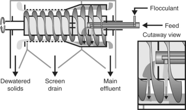
The incoming slurry is brought to rotational speed in an acceleration chamber before being evenly distributed through feed ports into the solid bowl chamber. Here, the solids settle under the influence of high G-forces (over 1000 g) and clarified water is discharged to effluent via an adjustable overflow weir located at the end of the machine. The settled solids are transported to the second stage of dewatering on the screen bowl section using a helical scroll that rotates at a slightly slower speed than the bowl. The scroll carries the solids up a beach section and onto the screen section. Here, additional moisture is removed prior to discharge of the final cake. The moisture is discharged through the screen drain outlet.
The moisture that is discharged through the screen contains, to varying degrees, fine coal. Early work conducted by Gallagher et al. (1981) indicated that the screen drain of an early model Broadbent screen bowl centrifuge contained around 30% solids. Conventional attempts to improve the recovery of ultrafine particles in the screen bowl centrifuge have centred on adding flocculent to the feed material (Miller and Wen, 1984). Many of these have been unsuccessful as, whilst the feed tends to flocculate adequately, the high shear environment within the screen bowl centrifuge tends to cause the flocs to break. In doing so, they release ultrafine particles back to the slurry, whereupon they tend to pass through the screen section and report to the screen drain.
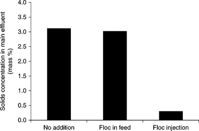
A novel approach (Burchett et al., 2006) of flocculent addition, however, has shown significant promise in the USA. The approach is to add flocculent direct to the solid bowl section of the screen bowl section, see Fig. 15.32. This overcomes the effects of high shear stresses that tend to break well-formed flocs presented to the centrifuge feed by adding flocculent directly into the machine and flocculating in situ. Whilst the exact mechanisms are not well understood, the net effect can be dramatic, see Fig. 15.33.
15.7.2 Centribaric™ centrifuge
This device is commercially available (see Fig. 15.34) and is claimed to produce significantly lower moisture content for fine coal products. The basis of the reduction in centrifuge moisture is identifying the existence of a negative pressure developed across the screen bowl unit which, ordinarily, would counteract the dewatering forces. By applying an air pressure during operation, the negative pressure difference can be overcome and more rapid dewatering facilitated (Keles et al., 2010).
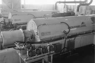
Table 15.2 provides a summary of the data obtained from prototype tests. The results show that a very low moisture value of 13.4% was achievable when treating the coarsest (37% minus 0.044 mm) feed stream. This moisture value steadily increased as the content of minus 0.044 mm particles in the feed stream increased. As such, the finest sample provided the highest overall moisture content of 19.7%, which is still considered to be very impressive given the extremely fine size of the feed (i.e. 96% minus 0.044 mm).
Table 15.2
Field data obtained with the Prototype CentribaricTM Technology
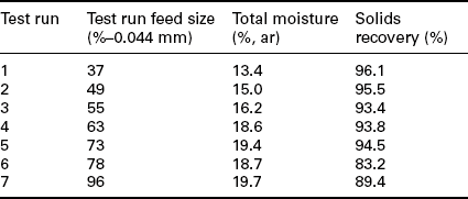
Source: Keles et al. (2010).
15.8 Drying
Drying is the process of removing water from coal by an evaporative operation. It is deployed in situations where the coal mass may freeze during handling and transport operations, thereby increasing the degree of difficulty of undertaking loading and unloading activities; it would increase the efficiency of downstream processes, for example cokemaking and electricity generation; or the quality of the coal for special applications can be improved, for example in the production of briquettes, chemicals and the like.
It is necessary to meet market-specified moisture content limits. This includes situations where coal type and/or mining method changes bring about increased fines loadings in coal preparation plant feed. In such cases, thermal drying may be necessary to maintain overall product moisture levels.
The total energy required to evaporate water comprises sensible heat that is required to raise the temperature to boiling point, and the energy required to vaporise the water. Sensible heat requirements can be estimated from values of the specific heat capacity at constant pressure. The variation of this parameter with temperature is shown by Fig. 15.35 (after Haynes, 2012), which indicates that as temperature increases, specific heat capacity decreases.
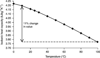
15.35 Isobaric heat capacity of water. (Source: After Haynes, 2012.)
The enthalpy of water vaporisation, like the specific heat capacity, is a fundamental thermodynamic property related to inter-molecular attraction forces. The variation of saturated state enthalpy of water vaporisation is shown in Fig. 15.36 (after Haynes, 2012).
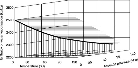
15.36 Saturated latent heat of water vaporisation. (Source: After Haynes, 2012.)
Over a 90 °C temperature range, the specific heat capacity varies by approximately 11%, and over an approximate 100 kPa pressure range, saturated latent heart of water vaporisation varies by around 9%.
Neglecting heat transfer inefficiency effects, which may be substantial, the heat energy required to vaporise water is many times that required to increase the temperature of liquid and coal to 100 °C. This is shown diagrammatically by Fig. 15.37, which graphically demonstrates that the main consumer of the input energy is the latent heat of water evaporation, with smaller amounts consumed in increasing the temperature of the water and the coal itself. Evaporating water is therefore an inherently energy intensive process, and any particular dryer should be regarded as being capacity rated on water evaporation rate rather than total feed rate (Leonard, 1991).
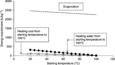
15.37 Showing relativity of energy required to heat and vaporise water (ignoring heat transfer inefficiencies) derived using data from Haynes (2012) and Perry and Chilton (1973).
15.8.1 Thermally drying of coal
Industrial thermal drying units apply heat, typically from hot gases formed by burning coal, directly to the wet coal mass. The heat is transferred to the wet coal and results in a reduction in the moisture content. The design of thermal dryers is sensitive to a number of factors, including ambient conditions, feed rate, feed size distribution and the reduction in moisture desired. There are a number of different types of thermal dryer technologies that can be used in coal applications. Due to the combustibility of coal, special care must be taken in the design and operation of such units to prevent and cope with the potential fires and explosions.
Typically the rate of moisture reduction depends on the particle sizes present, as shown for example by Fig. 15.38.

15.38 Drying curves at 105 ° C. (Source: After de Korte and Mangena, 2004.)
In general, a thermal dryer consists of three main functional sections:
There are various methods to generate hot air, including (Kofler, 2012):
Other sources of hot gases, for example waste gases from adjacent refractory processes;
These heat sources may be applied directly in the evaporation process or in some pre-heating application. Pre-heating applications are an option when low grade heat is available from a local source.
Water evaporation and discharge of dried coal
There are a number of different ways of evaporating water including:
Capture of airborne fine particles
Common methods for cleaning dryer waste gases prior to discharge to atmosphere include:
It is possible to use only one, a combination, or all three methods, depending on the duty and application. At high fines discharge rates it is normal to utilise a cyclone as a pre-cleaning step. Depending on local rules and regulations it may also be necessary to utilise filters or scrubbers. It is possible to use just a bag filter, but a cyclone in combination with a bag filter enables dry solids to be recovered and added to the final product.
Examples of direct thermal dryer systems
Typical direct coal drying technologies involve contacting the wet coal stream with heated gases such as combustion gases/air mixtures. The energy required for evaporation of the water is transferred mainly by convection, and the vaporised water almost invariably exits the drying stage contaminated with fine particles. Such dryers therefore include some mechanism of particle capture before venting the water vapour and combustion gases.
A typical direct contact rotary dryer is illustrated by Fig. 15.39 (after Mular et al., 2002), which consists of three main sections. The first section heats the air by burning the fuel, which then passes to the second section where the wet coal enters and is dried in the rotary unit. The dried coal exits from the bottom of the end hood, while the vapour/gas stream passes to the third section. This is a bag-house which captures much of the fine particulate material before exhausting to atmosphere. Figure 15.39 depicts a co-current design, and counter-current units are also available where solids and hot air pass in opposite directions.
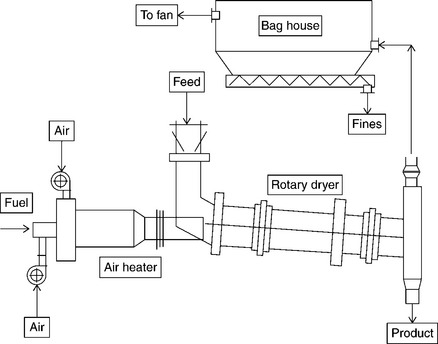
15.39 Direct contact rotary dryer. (Source: After Mular et al., 2002.)
A vertical fluidised bed is another form of direct drying system, shown schematically by Fig. 15.40, in which the hot combustion gases are used to fluidise the wet coal material. In this case, a cyclone is used to recover entrained coarser particles before passing the exhaust gases through a bag-house.
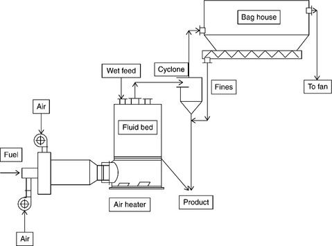
15.40 Vertical fluidised bed dryer. (Source: After Mular et al., 2002.)
Figure 15.41 shows two variations on an alternative fluidised bed dryer design in which a vibrating horizontal mechanism is used. These designs also show cool air inlets that enable additional control for possible overheating events.

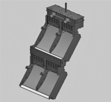
Figure 15.42 shows a photograph of a thermal coal dryer unit under fabrication at a manufacturer’s site (courtesy Binder + Co AG, Austria).
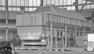
Figure 15.43 depicts a flash drying unit in which wet coal is added to a hot gas stream at a sufficient velocity so as to entrain all particles and carry them up the flash tube. The intimate contact between the gas and the wet solids facilitates very quick drying. In this arrangement, the cyclone is again used in conjunction with the bag-house to recover the dried coal particles. There is also an option to recycle product to achieve lower final moisture levels.
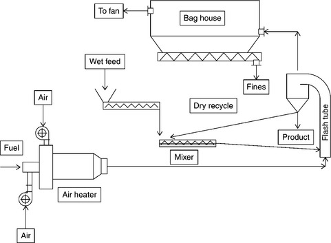
15.43 Flash dryer system. (Source: After Mular et al., 2002.)
Figure 15.44 depicts an air-swept hammermill dryer that can effect comminution and drying in the same unit. This arrangement also has a product recycle option.

15.44 Hammermill dryer. (Source: After Mular et al., 2002.)
15.8.2 Microwave drying
The natural vibrational frequency of the water molecules can be selectively targeted by microwaves such that only water heats up. Microwave drying therefore has potential advantages over thermal dryers in that heat energy is not wasted on heating the coal mass.
A proposed process to utilise the microwave drying concept, shown by Fig. 15.45 (Graham, 2008), involves measuring the moisture of the feed coal and applying microwave energy to achieve drying. Importantly, the coal surface remains at or below 90 °C so that neither volatile matter is lost nor coking properties affected.
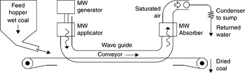
15.45 Schematic representation of a proposed microwave drying process (Graham, 2008).
15.8.3 Nano drying technology
This technology has been developed as an alternative to the capital and operating cost intensive thermal drying technologies.
A mechanical-thermal patent-pending dewatering process has been developed by NDT™. The process uses molecular sieves to imbibe water from wet fine coal particles; such technology has also been used to extract moisture from airborne aerosol and liquid environments.
The nano-sized particles are large enough to imbibe water but small enough to prevent any fine coal from entering. The process involves contacting the nano-sized particles with the coal, followed by separation by a screening operation. The nano-particles are regenerated by gas-fired means, with up to 70% thermal efficiencies claimed.
A bench scale study (Bratton et al., 2012) has concluded that the Nano Drying Technology proprietary system provides an effective method for coal drying. The NDTTM system can effectively dewater fine (1 mm × 0) coal from slightly more than 30% surface moisture to single-digit values. Test data obtained using a pilot scale unit validated this capability using a continuous prototype facility. It was also observed that, unlike the existing fine coal dewatering processes, the performance of the NDT™ system is not dictated or constrained by particle size, i.e. it works equally well on 1 mm × 0 coal as it does on 44 μm × 0 coal. The process overcomes problems associated with other techniques for fine coal drying since dewatering occurs at ambient temperature and low airflow. Only the molecular sieves have to be dried, which reduces energy. Moreover, this process produces no damaging contaminants and has a very small installed footprint and environmental impact.
15.9 Separation of clays
15.9.1 Fine coal screens
Fine coal screening technologies available, excluding those commonly used in high frequency dewatering applications, include the Derrick Screen, the Bivitec Screen and the Hein Lehmann Liwell Screen.
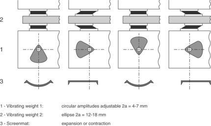
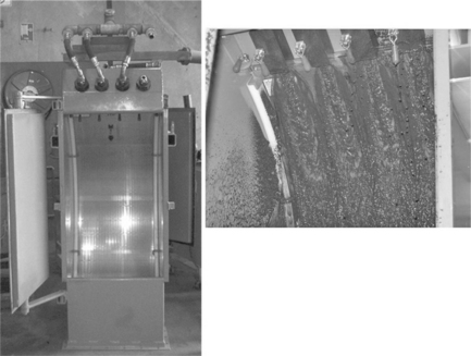
Binder + Co AG, and Hein, Lehmann Trenn-und Fordertechnik GmbH market flip-flop screens that are well suited to dry and wet screening of high clay content fine coal. The Binder + Co AG Bivitec screen incorporates a unique design that generates up to 50 g-force on individual particles; this compares to around 5–7 g-force associated with conventional screens (Vince, 2009a). This is achieved by using flexible polyurethane screen mats that attach alternately to a fixed and free-to-move cross beams. The Bivitec screening motion is shown schematically by Fig. 15.46. Figure 15.47 shows a photograph of a 3 m × 10 m Bivitec screening unit (Courtesy Binder + Co AG, Austria).

15.9.2 Sieve bends
Repulp sieve bends
Conn-weld Inc produces a repulp sieve bend, see Fig. 15.48. This device consists of an initial sieve bend that undertakes a primary separation. The overflow from this would typically comprise a 25–30% solids concentration slurry contaminated with misplaced undersize solids. The repulp launder permits the first stage overflow solids to be repulped to around 10–15% solids before passing to the second stage sieve bend. In this way, significant reduction of undersize contamination of the final product would be expected.
Pressure sieve bends
Conn-Weld produces a pressure sieve bend (see Fig. 15.49). Here, fine coal slurry is pumped under pressure through nozzles. The angle of incidence of the slurry combined with the high discharge velocity on the sieve bend surface promotes efficient separation of clays.
15.9.3 Baleen filter
The Baleen filter separates very fine solids (10 μm) and uses a double act of high pressure and low volume sprays, one which dislodges material caught by the filter media, whilst the spray sweeps the material away for collection. This process is claimed to remove even the most troublesome of constituents such as grit, suspended and fibrous matter, grease and oil from water without blocking the filter.
As water flows through the filter media, solids initially suspended in the water are left behind. But before they accumulate to block the screen media, the second spray transports these contaminants away from the filtering zone, enabling the filtering process to continue without disruption.
15.10 Other technologies
15.10.1 Micronised refined coal process
A Micronised Refined Coal (MRC) process is under development by CSIRO in Australia (Wibberley et al., 2008; Wibberley, 2011) as a source of slurry fuel for firing a modified diesel engine. This would form the basis of a low CO2 emission coal-derived base-load electricity generation system. It represents a modern and developing application of existing technologies, including the micronising step employing the IsaMill and column or supersonic flotation and technologies. In simple terms, the process comprises the following steps:
Micronisation of coal: This is achieved using the existing ISA Mill technology to achieve particles less than 20 μm in diameter. This is a wet procedure.
Cleaning of coal: This is achieved using froth flotation technologies, either Jameson Cell or Concorde Cell to achieve a concentrate with 2–3% ash.
The flotation process is followed by ‘trim’ dewatering.
The MRC product is designed to be utilised by high efficiency marinetype diesel engines.
15.10.2 Size enlargement
It is well known (Arnold et al., 1983; Fielder et al., 1983; Mikka and Smitham, 1983; Brown and Atkin, 2000; Bennett, 2008) that the proportion of fine coal affects the handleability of the bulk material. Mikka and Smitham (Fig. 15.50) in particular showed that at high fines content handleability was extremely sensitive to moisture content.
15.50 Effect of moisture and minus 0.5 mm coal fines levels on coal handleability test results (Mikka and Smitham, 1983). (Courtesy Australian Coal Preparation Society.)
Effective size enlargement has therefore received significant attention in the coal industry. There are a number of ways of increasing effective particle size available to the coal industry, only a small number of which will be discussed here.
Oil agglomeration
The natural hydrophobic surface properties of coal particles exploited in the fine coal froth flotation process may be utilised for effective particle size enlargement. To understand the mechanism, it is useful to consider the addition of oil to a mixture of coal, non-coal and water. Table 15.3 indicates that successively higher oil addition rates leads to differing effects.
Table 15.3
Effects of increasing oil addition to oleophilic coal particles
| Oil addition (mass %) | Action | Industrial process |
| 0.01–0.2 | Selective coating of hydrophobic coal particles | Froth flotation |
| 0.2–5 | Pendular flocculation | Oil assisted filtration |
| 5–30 | Agglomeration | Oil agglomeration |
At low levels of oil addition (0.01 –0.2 mass %), the oil tends to preferentially coat the surface of hydrophobic coal particles, thus forming the basis of the froth flotation process.
At higher levels of oil addition, it becomes appropriate to adopt a terminology that reflects the importance of oil to the process, with oleophilic and oleophobic used as adjectives to describe the behaviour of particles in the presence of oil. Oleophilic describes particles such as those of hydrophobic coal that are attracted to oil, and those such as particles of liberated mineral matter that are repelled by oil are termed oleophobic.
Moderate levels of oil addition (0.2 –5 mass %) in the presence of shear (e.g. stirring) tend to promote flocculation of the coated fine coal particles. Here, see Fig. 15.51, excess oil tends to accumulate at the contact points between oil-coated fine coal particles. The process described is termed pendular flocculation (Nicol, 2001) and can result in fine coal slurry becoming readily filterable (Nicol and Rayner, 1980).
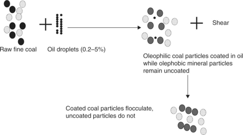
15.51 Schematic representation of fine coal pendular flocculation process. (Source: After Leonard, 1991.)
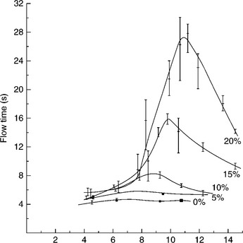
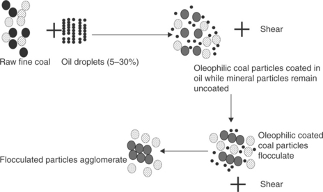
Higher levels of oil addition (5–30 mass %) in the presence of shear tend to promote agglomeration of the pendular flocs to form larger oleophilic agglomerate particles, see Fig. 15.52. The size of the agglomerates depends on the oil addition rate, for example see Fig. 15.53.
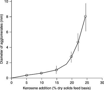
15.53 Effect of oil addition rate on diameter of agglomerate (Swanson et al., 1977). (Courtesy Australian Coal Preparation Society.)
Oil agglomeration has been used as the basis of a commercial process to upgrade colliery fines (Nicol, 2001), see Figs 15.54 and 15.55. It has also been used with tar oil (Haldar, 2005) to effectively upgrade fine coal.
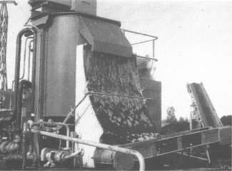
15.54 Photograph of 5 t/h oil agglomeration operation in Australia (Nicol, 2001). (Courtesy Australian Coal Preparation Society.)
15.55 Schematic representation of fine coal agglomeration process (Nicol, 2001). (Courtesy Australian Coal Preparation Society.)
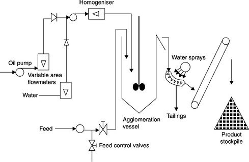
The technique of oil agglomeration has also been used as an Integrated Pipeline Transportation and Coal Cleaning System (IPTACCS) in which pipeline transportation of an oil/water coal system is also used to beneficiate and agglomerate fine coal. The process, shown schematically by Fig. 15.56, has been evaluated at pilot scale (Elkes et al., 1983).
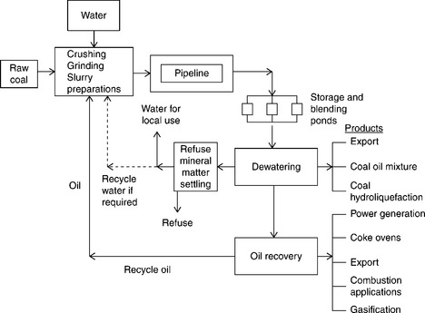
15.56 Schematic representation of IPTACCS process. (Source: After Elkes et al., 1983.)
Pelletising (granulating)
Pelletising is also known as granulating, and is a process, akin to oil agglomeration without the oil, in which moist fine coal is passed to a rotating drum and the rolling action of particle on particle promotes aggregation. The process mechanism has been described in terms of growth and breakage events (Sastry and Fuerstenau, 1972). These are shown schematically by Fig. 15.57.
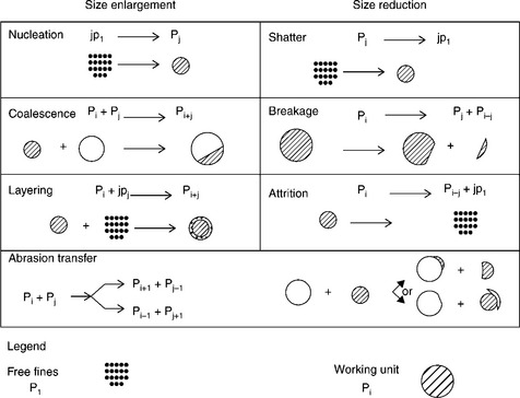
15.57 Schematic representation of pelletisation growth and breakage mechanism. (Source: After Sastry and Fuerstenau, 1973.)
In some cases it is necessary to use reagents such as petroleum fractions to achieve stable pellets that can be as large as several millimetres in diameter. In general, however, the pellets tend to exhibit insufficient strength characteristics to resist substantial degradation during normal handling operations. As a consequence the pelletising process has found application in at least one coal-fired power plant when handling bag-house dust material.
An industrial scale example (Hinkle, 1985) of this was the 2.4 MW Bruce Mansfield coal-fired station of Pennsylvania Power Company in Shippingport, Pennsylvania. Here a dust-collection system in the primary crushing plant collected dust fines generated by the crusher units and conveyor transfer points. This system removed the coal fines from the building and delivered the dust-laden air to the bag-house.
To facilitate re-use of the collected fines, a pelletising system was deployed which comprised:
The pelletised fines were returned to the power station feed system for power generation.
Briquetting
Briquetting is a process in which fine particles are pressed together under considerable pressure. Applications relate to improving transportation characteristics of export coals and pre-treatment directly prior to coke oven charging operations.
Briquetting to improve export coal handling characteristics
Binderless Coal Briquettes (BCB) is a proprietary process (White Energy Company, 20121) in which commercial strength briquettes are produced. The process is shown schematically by Fig. 15.58 and consists of:
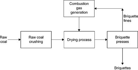
15.58 Schematic representation of BCB process. (Source: After White Energy Company, 2012.)
Crushing: Hot gas generation by burning briquette fines
Drying: Briquetting in high pressure presses.
Schematic representation of BCB process (after White Energy Company, 2012).
Briquetting to improve coke oven operations
Cognisant of existing coke ovens approaching the end of their design service lifespan, significant research and development effort has been undertaken by the Japanese steel industry to improve the economics of cokemaking.
A major programme has developed the dry-cleaned and agglomerated pre-compaction system (DAPS) for metallurgical cokemaking (Kato et al., 2006). The DAPS process, see Fig. 15.59, was developed as a means of enhancing coke strength and suppressing dust emissions. This is achieved by drying coal in a fluidised bed dryer, separating the coal fines (minus 0.3 mm) from the coarse material using a hot gas entrainment mechanism, and agglomerating the hot fines in a roll compactor.
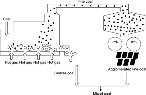
15.59 Schematic representation of DAPS processes. (Source: After Kato et al., 2006.)
Another example is the super coke oven for productivity and environmental enhancement toward the twenty-first century (SCOPE21) process that is in an advanced stage of development by JFE Steel Corporation (Fukada, 2005). This process includes a hot briquetting stage for coal fines prior to charging coke ovens, Fig. 15.60.
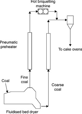
15.60 Schematic representation of hot briquetting stages of SCOPE21 Process. (Source: After Fukada, 2005.)
Often it is necessary to add briquetting agents, such as tar, oil, etc. to enable sufficiently strong briquettes to be formed. However, the use of such additives frequently renders standalone coal briquetting processes uneconomic.
In the coal context, briquetting has become a major enabling technology with application to coal and coke. It is a process that has not yet seen universal application, principally due to reasons of capital and operating costs.
15.11 Acknowledgements
The enthusiastic discussions with and information provided by Mr Glenn (Shoey) Schumacher (Gladstone Operating Services Pty Ltd), Dr Jim Smitham (CSIRO), Dr David Osborne (Xstrata Coal), Dr David Harris (CSIRO) and Dr R. Oder are gratefully acknowledged. Acknowledgement is also made to companies and individuals that have given permission to include copyrighted material:
15.12 References
in Arnold, P.C., McLean, A.G., Moore, B.A., Bulk solid storage and flow considerations for coal preparation plant 1A.. R.L., Whitmore. Proceedings of the Second Australian Coal Preparation Conference, 1983.
Bada, S., Falcon, L.M., Falcon, R.M.S., Honaker, R., Tao, D., A study of rotary tribo-electrostatic separation of South African fine coal Lexington, USA.. Proceedings of International Coal Preparation Congress, 2010.
Bratton, R., Ali, Z., Luttrell, G., Bland, R., McDaniel, B., Nano drying technology: A new approach for fine coal dewatering Lexington, USA.. Proceedings of Annual Coal Processing Exhibition and Conference, 2012.
in Bennett, P., Evaluation of the Edinburgh cohesion tester. D.J., Mathewson. Proceedings of the Twelfth Australian Coal Preparation Conference, 6B., 2008.
Boyd, R., Review of hypercoal, clean coal and rotating kiln technologies ACARP Project C16008., 2007.
Brown, D.W., Atkin, B.P., A coal handleability monitor for on-site measurements in. Proceedings of the Eighth Australian Coal Preparation Conference, 2000.
Burchett, R.T., McGough, K.M., Luttrell, G.H., Improved screen-bowl centrifuge recovery using polymer injection technology. Coal Prep 2006 Conference Proceedings. Lexington, 2006.
Cottrell, A., Scaife, P., Wibberley, L., Systems assessment of ultra-clean coal for electricity supply in Japan May.. CSIRO Energy Technology, 2004.
Cottrell, A., Scaife, P., Wibberley, L., Systems assessment of hypercoal for electricity supply in Japan July.. CSIRO Energy Technology, 2007.
De Korte, G.J., Mangena, S.J., Thermal drying of fine and ultra-fine coal CoalTech 2020 Report No. 2004–0255, July.. CSIR, 2004.
in Elkes, G.J., Rigby, G.R., Mainwaring, D.E., Enhanced coal recovery through IPTACCS technology. R.L., Whitmore. Proceedings of the Second Australian Coal Preparation Conference, 4B., 1983.
Fandrich, R., Gu, Y., Burrows, D., Moeller. Application of the coal grain analysis method to coal liberation studies. Modern SEM-based mineral liberation analysis, International Journal of Mineral Processing, 84:310–320, cited in O’Brien, G. Firth, B. and Adair, B., 2011. International Journal of Coal Preparation and Utilization. 2007; 31:96–111. [2011.].
Fielder, V.A., Sprague, C.M., Clarkson, C.J., Corr, N.G., Solving a stockpile coal handleability problem. R.L., Whitmore. Proceedings of the Second Australian Coal Preparation Conference, 1B., 1983.
Chapter 26-Plant studies and optimization Fuerstenau, D.W., De, A., Diao, J., Kapur, P.C., Fine grinding of coal in a two-stage high pressure roll mill/ball mill hybrid mode Society for Mining,. High Efficiency Coal Preparation: An International Symposium. Metallurgy and Exploration, Inc, Colorado, 1995.
Fukada, M., Development of new cokemaking process, SCOPE21 26–29 January, Cebu. proceedings ‘Clean Fossil Energy Technical and Policy Seminar. Asia-Pacific Economic Cooperation, The Philippines, 2005.
Gallagher, E., Lewis, J.E., Post, J.J., Swanson, A.R., Armstrong, L.W., Dewatering of fine coal by screen bowl centrifuges. A.R., Swanson. Proceedings of the first Australian Coal Preparation Conference, 1981:134–154.
Graham, J., Microwaves for coal quality improvement: The Drycol project. D.J., Mathewson. Proceedings of the Twelfth Australian Coal Preparation Conference, Paper 10B, 2008.
Haldar, D.D., Technologies for fine coal beneficiation in India 26–29 January. SCOPE21, proceedings ‘Clean Fossil Energy Technical and Policy Semina. Asia-Pacific Economic Cooperation, Cebu, The Philippines, 2005.
Haynes, W.M. CRC Handbook of Chemistry and Physics, 93rd Ed. Boca Raton, USA: CRC Press; 2012.
Hornick, M.J., Gasified biomass co-fired with coal at the Tampa Electric Company April 16–17. Proceedings, Second DOE/UN International Conference and Workshop on Hybrid Power Systems. The National Energy Technology Laboratory, USA, 2002.
Hinkle, R.G., Case history: Agglomeration of coal fines at a fossil fuel power station 1985.. Institute for Briquetting and Agglomeration; 19, 1985.
Hise, E.C., Wechsler, I., Doulin, J.M., The continuous separation of dry crushed coal at one tonne per hour by high-gradient magnetic separation December.. Oak Ridge National Laboratory (ORNL-5763), 1981.
Hise, E.C., Correlation of physical coal separation – part 1 September.. Oak Ridge National Laboratory (ORNL-5770), 1979.
Hwang, J.Y., Fine coal cleaning with advanced magnetic enhancement technology. Proceedings of the Sixth Annual Coal Preparation, Utilization, and Environmental Control Contractors’ Conference, 1990:290–297.
Hwang, J.L., Lui, J., Gray, M.L., Coal cleaning with magnetic reagent SME pre-print number 92–227, 1992.
Hwang, J.Y., Magnetic reagent technology for mineral industry Phoenix, Arizona, preprint.. AIME SME Annual Meeting, 1992.
Jameson, G.J. New directions in flotation machine design. Mineral Engineering. 2010; 23:835–841.
Kato, K., Nakashima, Y., Yamamura, Y., Development of dry-cleaned and agglomerated pre-compaction system (DAPS) for metallurgical cokemaking July.. Nippon Steel Technical Report, No. 94, 2006.
Keast-Jones, R., Smitham, J.B., Ultra low ash coal production. P., Holtham. Proceedings of the Fourth Australian Coal Preparation Conference, 7A, 1988.
Keles, S., Luttrell, G.H., Yoon, R.H., Eraydin, M.K., Schultz, W., Taking advantage of the Centribaric™ Technology. B&S, Atkinson. Proceedings of the Thirteen Australian Coal Preparation Conference, 8A, 2010.
Keles, S., Luttrell, G., Yoon, R.-H., Estes, T., Schultz, W., Bethell, P., Development of the Centribaric dewatering technology. R.Q., Honaker. 2010 International Coal Preparation Congress Conference Proceedings, 2010.
Kofler, T. Personal communication. Austria: Binder + Co AG; 2012.
Kindig, J.K., Goens, D.N., The dry removal of pyrite and ash from coal by the Magnex process – coal properties and process variables EPA Report 600/7/-79-098b.. Proc. Symp. on Coal Cleaning to achieve energy and environmental goals; II, 1979.
, Coal preparation. J.W., Leonard. Society for Mining, Metallurgy, and Exploration, Inc, Littleton, Colorado, 1991.
Liu, Y.A., Physical Cleaning of Coal. Marcel Dekker, New York, 1982.
Liu, Y.A., High-gradient magnetic separation for coal desulpurization Marcel Dekker, New York.Liu, Y.A., eds. Physical Cleaning of Coal, 1982.
Mamaghani, A.H., Beddow, J.K., Vetter, A.F. Chemical comminution of coal. AIChE Journal. 1987; 33(2):319–321.
Meyers, A.D., Wex, T., Leach, K.R., Solids partitioning in screenbowl centrifuges. B.A., Firth. Proceedings, Nineth Australian Coal Preparation Conference, Paper E2, 2002.
Mikka, R.A., Smitham, J.B., Coal handleability assessment. C.N., Bensley. Proceedings of the Third Australian Coal Preparation Conference, 1B, 1985.
Miller, K.J., Wen, W.-W., Effect of Operating Parameters and Reagent Addition of Fine Coal Dewatering in a Screen Bowl Centrifuge DOE/PETC/TR-85/1 (DE85002885). Pittsburgh Energy Technology Center Report, 1984:19.
Mular, A.L., Halbe, D.N., Barratt, D.J., Mineral processing plant, design, practice, and control Volume 2. Society for Mining, Metallurgy, and Exploration, Inc, Littleton, Colorado, 2002.
Norrgran, D.A., Mankosa, M.J., Selection and sizing of magnetic concentrating equipment; plant design/layoutMular, A.L., Halbe, D.N., Barratt, D.J., eds. Mineral Processing Plant Design, Practice, and Control Proceedings, 1. Littleton, USA: Society for Mining, Metallurgy, and Exploration, Inc, 2002.
Nicol, S.K., Fine coal beneficiation Part 9.Swanson, A.R., eds. Australian Coal Preparation Monograph Series; IV, 2001.
Nicol, S.K., Rayner, J.G. Oil assisted filtration of fine coal. International Journal of Mineral Processing. 1980; 7:129–135.
Oberteuffer, J.A., Arvidson, General design features of industrial high gradient magnetic filters and separators IEEE publl. No. 78CH1447-2 MAGLiu, Y.A., eds. industrial applications of magnetic separation. Institute of Electrical and Electronic Engineers, New York, 1979.
O’Brien, G., Firth, B., Adair, B. Application of the coal grain analysis method to coal liberation studies. International Journal of Coal Preparation and Utilization. 2011; 31:96–111.
Oder, R.R., High gradient magnetic separation: Theory and application Mag-12. IEEE Trans. Magn, 1976:428.
Oder, R.R., Personal communication, 2013.
Oder, R.R., Hurst, R., Jamison, R.E., Emission reduction and plant efficiency improvement using the MagMill™ Pittsburgh, PA, 29 September—2 October.. Proceedings of the 25th Annual International Pittsburgh Coal Conference, 2008.
Oder, R.R., The MagMill: Innovation in dry coal cleaning technology enhancing environmental compatibility and resource sustainability 24–26 September, Taiyuan, China.. presented at the BIT 1st International Symposium of Clean Coal Technology, 2012.
Ofori, P., O’Brien, G., Firth, B., Jenkins, B., Flotation process diagnosis and modelling by coal grain analysis. W.B., Wembrey. Proceedings of the Tenth Australian Coal Preparation Conference, C9, 2004.
Okuyama, N., Komatsu, N., Shigehisa, T., Kaneko, T., Tsuruya, S. Hypercoal process to produce the ash-free coal. Fuel Processing Technology. 2004; 85:947–967.
Osborne, D.G., Coal Preparation Technology Volume 2, 1988. [Graham and Trotman, London.].
Perry, R.H., Chilton, C.H. Chemical Engineer’s Handbook, fifth edition. McGraw-Hill Book Company; 1973.
Rahal, D., Roberts, K., Rivett, T., Knelson-Deswik mill: Evaluation of operating variables Co, Preprint 11–050.. SME Annual Meeting, 27 February–2 March, Denver, 2011.
‘Kinetic and process analysis of the agglomeration of particulate materials by green pelletization’, Agglomeration 77, Vol. 1, Chapter 21.
Schumacher, G., Coal pulverising mill types unpublished work., 2010.
Schumacher, G., Private communication, 2012.
Steel, K., Chemically cleaning coal July:52–53.. The, Chemical Engineer, 2007.
Swanson, A.R., Bensley, C.N., Nicol, S.K. Some fundamental aspects of selective agglomeration of fine coal. Atlanta, Georgia: Proc. 2nd Int. Symp. on Agglomeration; 1977.
Taggart, A.F. Handbook of Mineral Dressing. New York: John Wiley; 1953.
Thomas, L. ‘Coal Geology. Chichester, United Kingdom: Wiley; 2012.
Trass, O., The Szego Grinding MillVegas, Las, Somasundaran, P., eds. Proc. of Int. Symp. on Fine Particles Processing; I. Society of Mining Engineers, AIME, 1980:96–112.
Vince, A., Comminution Materials Handling.Sanders, G.J., eds. Advanced Coal Preparation Monograph Series; II, 2009.
Vince, A., Screening Materials Handling.Sanders, G.J., eds. Advanced Coal Preparation Monograph Series; II, 2009.
Weiss, B.M., Maddocks, R.R., Howard, P.H. Chemical comminution for coal cleaning. In: Liu Y.A., ed. Physical Cleaning of Coal Present and Developing Methods. New York: Marcel Dekker, Inc, 1982.
Energy Company, White www.whiteenergy.com/our-coal-technology/the-white-coal-technology-process/, 28 December 2012
Wibberley, L., Palfreyman, D., Scaife, P. Efficient use of coal water fuels technology assessment report 74. Pullenvale, Qld, Australia: QCAT Technology Transfer Centre; 2008.
Wibberley, L. Coal base-load power using micronised refined coal (MRC). January–March. Energy Generation. 2011; 35–39.
Wills, B.A. Wills’ Mineral Processing Technology’. Elsevier; 2006.
15.13 Appendix: Nomenclature and abbreviations used
| Alowest | Lowest ash value (%) of a tree flotation fraction in a properly constructed tree flotation curve. |
| CGA | Coal grain analysis. |
| CSIRO | Commonwealth Scientific and Industrial Research Organisation. |
| d50 | Particle size representing fiftieth percentile of cumulative particle-size distribution curve (μm). |
| g | Acceleration due to gravity (ms− 1). |
| HPGR | High pressure grinding rolls. |
| ICGCC | Integrated Coal Gasification Cycle electricity generation plant. |
| MLA | Mineral liberation analysis. |
| PCI | Pulverised coal injection. |
| QEMSEM | Quantitative evaluation of minerals by scanning electron microscope. |
| SMD | Stirred media detritor mill. |
| ww | Wedge wire screen aperture. |
1There may be a need to crush the material.