Coal handling along the supply chain
Abstract:
This chapter discusses the possibilities of the use of materials handling machines for coal applications. It gives an overview on conveying, storing, loading/unloading and crushing for coal in today’s industry environment. It talks about different coal industries and would like to encourage a cross-industry and out-of-the-box style of thinking. The chapter will give a general approach to the selection of equipment for the different needs of coal applications. Details will not be discussed and can be further explored in separate literature.
20.1 Introduction
Although bulk materials handling technology has developed quite rapidly over the recent years, the fundamental design criteria and applications remain more or less unchanged.
The main focuses today are on safety, efficiency, quality, costs of design and construction and, of course, higher capacities.
The growing globalization of markets demands more investigation of transportability and constructability, which adds additional levels of complexity to the execution of materials handling projects.
In some areas of the world, original equipment manufacturers (OEM) and machine designers face issues with some business models applied, which involve more and more engineering companies defining materials handling machines and processes up to the last bolt and nut. One might claim, on the one hand, this does not do any good for materials handling development, invention or creativity but, on the other hand, it does allow certain market segments to standardize and plan more efficiently with the existing designs.
However, the question remains how the industry can improve time-lines, costs, and also the safety and quality of materials handling plants.
20.1.1 Coal flow sheet
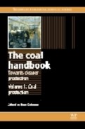
A typical coal (process) flow sheet involves a series of processing equipment, materials handling equipment and auxiliary equipment, e.g. sampling plants, dedusting units, utility systems, and others (Fig. 20.1).
The materials handling equipment is used to link processes but also to link different machinery and, as such, is an integral part of plant/process planning (Fig. 20.2).

Whereas it is extremely important to design processing equipment correctly, it is just as important to consider an optimized materials handling plant in order to avoid material segregation, deterioration of raw material or finished product, double handling of materials, improvement on overall amount of materials and structural steel used, etc.
In short, the right selection of stackers and reclaimers, together with belt conveyors, loading and unloading machinery, and auxiliary equipment is just as important, and definitely price- and quality-driving as the definition of the right process choices and definitions.
The outline below will give some ideas and pre-selection criteria for choosing the right approaches for coal handling plants in different market segments.
20.2 Conveying
In general, conveying systems connect process or materials handling machines, and are widely used in the industry. An intelligent connection and combination of different technologies available in the market will allow defining the best possible solution for the respective application.
A very good overview concerning belt conveying developments and design features is given in Chapter19. Different types of conveying equipment with some typical applications are also mentioned in other chapters.
20.2.1 In-plant conveyors
In-plant conveyors are widely used in all coal applications, with belt widths ranging from 400 up to 2500 mm (and wider) depending on application and capacities.
Predominant calculation methods are included in CEMA and DIN standards.
Typical applications can be found in mines, preparation plants, port facilities, etc. with capacities starting from a few hundred tons per hour to high export rates of ten to fifteen thousand tons per hour.
As for all industries and markets, the right application of norms, standards and regulations under actual side and site conditions is the key to a successful design, especially in belt conveyor design, where perhaps, much too often, a ‘cut-copy-paste design’ is adopted, and different temperature levels, material flow characteristics, or changed process requirements are often overlooked. It is also much too often the case that the industry has to refurbish plants, for which crucial aspects such as safety assurance, accessibility, maintainability, etc. were neglected in the original design.
With the existing expertise and experience in belt conveyor and transfer chute design, designers are able to produce very good belt conveying systems; but these will still always have to be re-checked and re-validated, to ensure that the right level of knowledge is applied.
20.2.2 Overland conveyors
In general, the requirements for overland conveyors and conveyor systems grow with the expanding materials handling capacities, loading times and connectivity when compared with those of road haulage using trucks.
New technology developments, such as intermediate drives, higher belt qualities, low friction idler rollers, more efficient electrical and control system support, and combinations with curved belt/pipe conveyors, can also make overland conveying systems more and more viable in comparison with other means of transportation.
Examples of overland conveying systems of 100 km and more already exist, and many have worked for several years.
One of the biggest challenges for designers is the integration of new technologies with safety and also environmental requirements. The biggest question is how to merge industrial conveyor design with architectural design to avoid further ‘pollution’ of our already stretched environment.
Overland conveyors are dealt with in further detail in Chapter 19.
20.2.3 Pipe conveyors
Pipe conveyors were developed in the late 1970s and have since been further improved. Today, the pipe conveyor is a proven technology with many applications all over the world. The main reason to think ‘outside the box’ of conventional conveying is that green-field and brown-field coal plants often require special applications in extreme field conditions, i.e., in congested existing industrial facilities, and always in alignment with health, safety and environment (HSE) requirements and other regulations.
The pipe conveyor technology comes into play when some of the following questions are asked:
Can transfer towers be avoided?
Are there special requirements concerning environmental protection, e.g. protected marshland with special fauna and flora?
Are steep inclines necessary to reach high/low points over the shortest possible distances?
Is there a congested existing facility between the two machines/process areas requiring connection?
Can material spillage from the lower strand be avoided and with it the maintenance and cleaning activities along the conveying route?
The pipe conveyor principle:
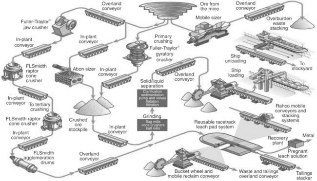
The heart of the pipe conveyor is a flexible rubber belt that forms a pipe/ tubular shape during transportation. In the material loading area, the conveying belt is still open. The material is charged in the same way as with a conventional belt conveyor. Once the material is loaded, special devices close the belt, securely enclosing the material within the formed pipe. For the entire conveying line, the belt forms a sealed pipe. Thus, the content is protected against external influences, while the environment is protected against any potential material losses. At the end of the conveying line, and before the discharge point, the belt opens on its own, forms a troughed belt conveyor, and the material is discharged. The belt then closes again so that on the way back, it is also rolled in a tubular shape with the ‘dirty’ side inside, eliminating the risk of contaminating the conveyor line with spilled material (Fig. 20.3).
Along the whole conveying line, the tubular belt is guided by idlers that are arranged in a hexagonal shape, and is able to negotiate curves in any direction. The curves can be horizontal, vertical, or a combination of both, with a minimum radius of 300 or 500 times the tube diameter for fabric or steel cord belts, respectively. (These minimum radii may vary depending on the application, the belt material, the length of the conveyor, etc.)
This geometry allows a pipe conveyor to be installed with a multitude of curves in place of a network of conventional conveyors and the associated transfer points. The resulting elimination of transfer stations reduces the need for additional pulleys, chutes, dust collection or dust suppression systems, electrical power supply equipment, and foundations. Fewer material transfers also mean minimized material degradation. Further, the exclusion of transfer stations translates into an elimination of the associated maintenance requirements.
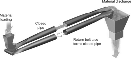
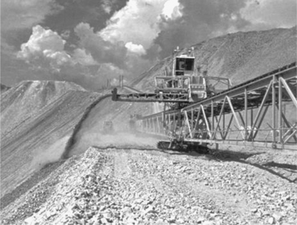
With lengths of 10 km and more without transfer stations, pipe conveyors are easily able to handle not only long distances but also problematic topographical areas (Fig. 20.4).

Thus, pipe conveyors can transport bulk materials dust-free over roads, tracks, waterways or open seas, through existing plants, over public streets, in environmentally protected zones. A special design of the idlers minimizes noise emissions so that pipe conveyors can be operated even in close proximity to residential areas.
The pipe conveyor can also negotiate steep angles of inclination. The enclosed round cross-section of the pipe increases the surface contact between the material and the belt, allowing a 50% increase in the angle of incline to about 30°. With these steeper incline angles, the elevated run of the pipe conveyor may become shorter. A pipe conveyor having the same conveying capacity as a conventional belt conveyor occupies about only 65% of the space required by a conventional belt conveyor. This is especially interesting for areas with limited space, e.g. tunnel or mining applications, as well as for installations in existing plants where pipe conveyors can wind easily around buildings, across roadways, other transportation lines, etc.
As a result of customized designs, even the most complex applications can be incorporated in a pipe conveyor system:
Multiple feed points can be integrated along the conveying line.
Reversible designs, a pipe conveyor can work as a two-way-system (see Fig. 20.5).
On steep downhill grades, pipe conveyors may be equipped to make use of the elevation drop to generate electrical power.
With a movable head station pulled by a crawler, the discharging station can be designed to be flexible within a certain radius.
Special arrangements of the pipe conveyor lines above or alongside each other allow the installation of several pipe conveyors in a minimum of space.
As there are no transfer stations along the conveying line, pipe conveyors allow simultaneous conveying on the feed and return belt even over long distances. Equipped with a belt turning station at the discharge point, an additional feed connection for conveying different material on the return belt may be realized.
The pipe conveyor utilizes the same standard conveyor components as a conventional belt conveyor. This means that no specially designed items are required. Standard idler rollers, pillow blocks, drives and other standard components of conventional belt conveyors can be used.
And while pipe conveyor belting is different in its structure, there are a number of manufacturers worldwide producing it.
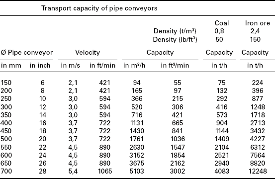
The proven design, high handling capacities, and the availability of standard components familiar to customers promotes the pipe conveyor as an acceptable alternative to, or a good combination with, conventional belt conveyors. Table 20.1 gives an overview on approximate handling capacities of pipe conveyors.
20.2.4 Apron feeders and belt feeders
Apron and belt feeders are widely used in the industry and can be found for a large variety of applications, e.g.:
Feed to and discharge from primary crushers;
Loading and unloading trucks and railcars;
Removing frozen materials from storage;
Feeding belt conveyors for metering weighing;
High-abrasion applications frequently found in reclaim circuits; and
The design of belt and apron feeders is fairly standardized, and most of the producing companies use pre-defined models and calculation methods to get short delivery times with a low-cost approach. The main features of the apron and belt feeders are:
Use of standard components (e.g. caterpillar chains/conveyor belts, idlers, pulleys);
Very robust construction providing long life;
Variable or constant speed drives;
Although the conveying devices are reasonably well defined and standardized, there is still room for improvement of the overall plant layout and construction, e.g. crushing plant, silo discharge system, train unloading system, etc. One of the most obvious ways to improve the overall design of such systems is to develop a better understanding of the equipment itself. Today, most OEMs want to be involved in the process of seeking the solution rather than only the supply of the equipment. This will enable the market to make use of the expertise of the equipment supplier and, at the same time, use their knowledge base for developing a wider scope, including other aspects such as silo design, hopper design, electrical and hydraulic issues, etc.
20.2.5 Drag chain conveyors
Drag chain conveyors are used for special transportation of smaller capacities. Drag chain conveyors work on the principle of a chain-and-flight combination pulling a volume of material along. The chain is equipped with different flights/paddles and drags the material from various charging points to a number of discharging points.
The enclosed conveying device is used mainly for dusty, abrasive or hot material and, as such, has only a very limited application in coal. However, the power plant industry and other coal industry players ask for specialized conveying systems, for which the very flexible drag chain conveyor might be a solution.
Horizontal, vertical or inclined solutions, with a possible explosion-proof and dust-tight design, might be necessary for some special applications in the coal industry.
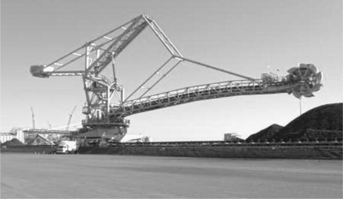
20.2.6 Mobile and movable/shiftable conveyors (overburden, rejects)
Movable and/or mobile conveyors were mainly developed for transporting overburden, reject, waste and tailings material.
These material handling components are specifically designed to enable large heaps and piles of material to be developed with as much flexibility as possible, i.e. the equipment needs to be relocated frequently in order to extend piles and storage areas (Fig. 20.6).
These material handling systems receive the material from process plants and convey and distribute via the following options:
For a long time movable conveyors were planned to be skid-mounted, and the shifting of belts and drive stations had to be done with mobile equipment and operational personnel.
Latest developments have promoted fully automated and crawler-mounted stacking systems. For some areas, especially in tailings systems, these systems can be combined with the appropriate filtration systems in order to improve on the overall water usage for plants.
All over the world, reduced water requirements, tangible water-saving issues, and environmental requirements lead to the requirement to develop new materials handling systems for the tailings/waste management in mines and processing plants.
The technology behind the mobile stacking conveyors and crawler-mounted stackers is well proven, operating at up to more than 12 000 tph. It is again a question of using technologies developed for other industries in order to get a better outcome for the coal industry.
The combination of filtration technology and materials handling made a so-called ‘dry stack tailings system’ an ideal choice for dry climate mining operations. Along with reduced water requirements (achieved through process water recycling and the virtual elimination of water losses through evaporation and/or seepage), other direct benefits include substantially smaller tailings storage footprint and improved site rehabilitation potential. In this application, some form of mechanical dewatering device will be needed to reduce the retained moisture content of the tailings to around 15%, giving the tailings a handleable consistency. The tailings material could then be delivered to the designated storage area by conveyor and dispersed from the mobile stacking conveyor. An area 2 km × 2 km (4 km2) has been allocated for tailings storage. By comparison, if the more traditional pond storage system was to be utilized, an equivalent area of around 52 km2 would be required to store the tailings in this project. In many cases, especially when the clay content of the tailings is low, this form of disposal is both feasible and economical.
Constructed of space frame truss sections, the system is mounted on crawler tracks that level and move individually to maintain the required levelling and alignment as material is continuously stacked. These systems are fully automatic and controlled by a global positioning system (GPS). Various ‘sweeps’ and layers are gradually built up, sometimes up to 90 m in height. Further reasons for selecting such a relatively new system are the environmental possibilities for future reclamation and revegetation.
In short, the engineering expertise and knowledge from other industries will enable the coal industry to create fully automated machines, which will improve operational efficiency, be environmentally friendlier, and involve minimal manpower.
20.2.7 High-angle conveyors
The coal industry increasingly demands a wide variety of standard, mobile, movable conveyors, crushing stations, and also special belt conveyors such as high-angle conveyors. Engineers usually begin by comparing different technical solutions, e.g. truck transportation vs belt conveying. Specialized options, such as in-pit-crushing and conveying (IPCC) technology, seek ways of optimizing the mining approach. One of the key questions, when changing the mining approach from predominantly shovel-truck operation to a conveying operation, is how to get the material out of the pit in the shortest possible path. One solution is to use a high-angle conveyor, which can be designed to be much steeper than a conventional troughed belt conveyor.
Different technologies are still emerging and will soon add value to the mine operations. Depending on the mine planning, available ramps, highwall angles and other conditions, a number of options are available, including the sandwich belt, variants of the pipe conveyor (described earlier), or a series of ‘grasshopper’ type conveyors, etc.
20.3 Coal storage
Some form of storage is usually needed for various reasons between two connected processes. The key is to select the correct storage and the right size for the application.
The tendency has often been to opt for a previous ‘design’ rather than to design for the specified needs. Since the different applications are never exactly the same the tailored approach is recommended and some very basic questions include the following:
Disconnection of mine and process, or vice versa
Compensation of shut-down times
Buffer storage for material delivery (e.g. ship, truck, train)
What are the parameters for the right storage selection?
Environmental and climatic condition
What is the right size of storage?
Depending on the longest dead time of mine operation
Based on the target standard deviation of the raw material
Depending on usage of storage facility
Depending on how many different qualities/types of material need to be stored separately
Some industries use a ‘rule of thumb’ approach, e.g., 15–30 days of coal consumption in process
All these questions are very basic, although still needing to be taken into account. However, answering these questions and evaluating them properly can often create the need for very complex evaluation models to define the right storage approach.
20.3.1 Introduction to stacking
Similar to the approach in the previous section, some very basic theory needs to be considered for selecting the right stacking equipment. Stacking is only one component of material storage. The correct combination between stacking and reclaiming is needed to get the required results for the application.
Stacking for conical stockpile:
Stacking from a high point to form a conical pile.
Stacker is fixed and cannot move in any direction.
Reclaiming is carried out by mobile equipment; or via underground extraction by means of vibrating feeder, belt feeder, coal valves, etc.
Stacking for kidney-shaped stockpile:
Stacking from a high point of discharge.
Stacker is pivoting around a fixed point to form the kidney-shaped pile.
Reclaiming is carried out by mobile equipment, or underground extraction via vibrating feeder, belt feeder, coal valves, etc.
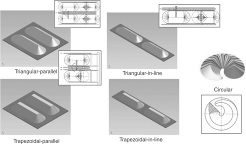
Chevron stacking (Fig. 20.7):
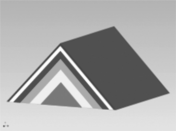
Stacking into roof like layers with a travelling stacker.
The stacker is a luffing type, (raised and lowered) to reduce the dust generation.
Yard cross-section during stacking is non-homogeneous due to segregation effects.
During reclaiming, homogenization can be achieved only if machines capable of reclaiming across the whole cross-section, such as bucket wheel machine, bridge type scrapers, bridge type bucket wheel, and drum-type reclaimers, are used.
Windrow stacking (Fig. 20.8):

Stacking in cells built up with a Chevron approach.
Using the same stacker as with the strata method (see later), i.e., by means of luffing and slewing – or telescopic.
Good homogeneity of the stockyard cross-section.
Face reclaiming by bridge type bucket wheel machines, bridge type scrapers or bucket wheel reclaimers and drum reclaimers.
A longer boom is necessary to reach across the entire stockpile width.
Best material homogenization is achieved during stacking, avoiding segregation.
Strata stacking (Fig. 20.9):

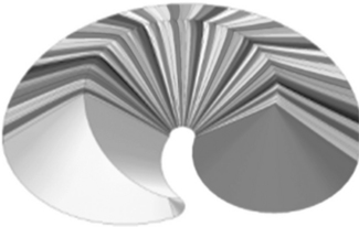
Cone-shell stacking (Fig. 20.10):

Stacking in shapes of cone shells with a travelling stacker.
Depending on requirements, a luffing, or slewable stacker is necessary.
Chevron stacking (Fig. 20.11):
Stacking with Chevron method is a combination of cone-shell and Chevron, applied to a circular stockpile.
Stacking in sections, or governed by the angle of repose; after a cone has been built, travelling back and forth moving in the direction of travel (by a distance, corresponding to the first cone).
Stacker must be capable of luffing and slewable.
At a continuous operation, a good homogeneous stockyard can be achieved.
Reclaiming is usually done with bridge type scrapers and bridge type bucket wheel reclaimers.
All these different stacking methods (and combinations of them) result in various stockyards and also machine layouts and requirements (Fig. 20.12).
The following stacking equipment is used in the coal market to form these described stockyards. Depending on the type of stacking equipment there are limitations when it comes to different stacking methods as described above:
Mobile equipment (no further discussion in this chapter).
Belt conveyor (fixed/slewing): The simplest stacking equipment, after the usage of mobile equipment, is a belt conveyor which is fixed and forms a cone pile.
Overhead gantry belt conveyor with tripper cars: a longitudinal pile is formed with a tripper car chute or a conveyor belt distributing the stacked material to one or both sides of the stacking belt (Fig. 20.13).

The choice of right stacking equipment requires detailed investigation of capacity, norms, conditions, requirements, etc. Unfortunately, some suppliers may opt for employing machine design parameters that are copied, or re-used from earlier applications. This general development in machine design will lead to non-optimal solutions and probably unnecessarily higher operational costs in the long term. This issue needs to be critically reviewed, especially under stretched and difficult economic situations (Fig. 20.14).

20.3.2 Bucket wheel machines
Bucket wheel reclaimers, or combined bucket wheel stacker reclaimers, are used for high capacity stacking and reclaiming in coal applications.
The main types of bucket wheel reclaimers can be defined as follows:
Boom type bucket wheel reclaimer (and combined stacker/reclaimer)
Bridge type bucket wheel reclaimer
Single bucket wheel bridge type reclaimer
Depending on the application, the different machines have their pros and cons. In coal applications the boom type machines are most common and reclaim (and stacking) capacities range from a few hundred tons per hour up to 10 000–15 000 tons per hour.
The boom type bucket wheel reclaimer consists of a vertically mounted rotating bucket wheel mounted at the end of a slewing and luffing boom. The reclaiming is done by a combination of slewing, travelling, and turning of the bucket wheel. The reclaim capacity is defined by the speed of travel, slewing, cutting speeds, cutting depth, and size of the buckets and bucket wheel. Several benches are taken into account for the reclaiming function, and the determination of the average reclaiming capacity must be properly evaluated to determine the maximum reclaim rate requirement and with that the necessary sizing of subsequent materials handling equipment.
The blending capability of the material is limited and, as previously stated, will also depend on the stacking method.
Boom type bucket wheel reclaimers can achieve the highest reclaim rates, can be used for two parallel piles, and can also be built as combined machines with stacking and reclaiming mode combined in one machine (Fig. 20.15).
Similar to scraper reclaimers, the bucket wheel machines can be fully automated, but the automation required is slightly more complicated due to the more complex combination of machine movements.
A full discussion of the design of bucket wheel reclaimers is not possible in the framework of this chapter; it must suffice to mention two of the main and basic design decisions that must be made. Tables 20.2 and 20.3 show the pros and cons of the choice of different pylon and bucket wheel designs.
Table 20.2
Bucket wheel reclaimer design 1
| Type of design | Advantages | Disadvantages |
| Pylon support (Ballast moves with BW boom) | Light weight design No bending moments on pylon Low centre of gravity |
No space for loop car, not usable for combined machines |
| C-Type (with clearance for Loop Car) | Free access for loop car and bypass | Large shifting of centre of gravity during luffing More heavy due to bending moments on pylon |
| Pantographic design | Low shifting of centre of gravity Cost savings on ball bearing, lower car and travel drives |
More expensive due to additional pivot points More sensitive against wind and earthquake |
Table 20.3
Bucket wheel reclaimer design 2
| a) | Cell-less bucket wheel - Most common design - Better discharge conditions - Higher cutting speed - Requires inner ring chute |
| b) | Cell bucket wheel - For special use only - Less capacity - Less maximum cutting speed - Not for sticky material |
| c) | Semi-cell bucket wheel |
Bridge type bucket wheel reclaimers and barrel reclaimers represent an alternative to a front-face reclaiming machine with scraper reclaimer. In very simple terms, the reclaim capacity is reached by a combination of rotating speed of the wheel or barrel, combined with the travel speed. For the bridge type bucket wheel reclaimer the activation of the material over the full face is done in a similar way as for the bridge type scraper reclaimer. The barrel reclaimers reclaim at the full face of the pile and have by far the best blending effect (Fig. 20.17).

20.3.3 Scraper reclaimer
The scraper reclaimer machines can in general be subdivided into front facing reclaimers and side scrapers.
Portal scraper reclaimers consist of a boom with scraper blades suspended from an A-frame which travels on rails along a stockpile. The scraper boom is equipped with sprockets pulling the reclaim chain around drive, bend and tail sprocket. Scraper blades are attached to the chain and ‘scrape’ the coal towards the reclaim conveyor. Most of the portal scrapers in the coal industry will have a bent chain to transport the coal from the bottom of the pile up to a discharge point above the reclaim belt conveyor. Other industries, e.g. the cement industry, would use an expensive concrete table, over which the material is dropped onto the belt conveyor. This eliminates the need for the chain to be bent but, as stated earlier, it is a costly exercise when it comes to the construction of necessary civil works.
The scraper boom is lowered after each traversing travel and, with that, cuts into the pile as it reclaims the coal.

20.16 Bucket wheel reclaimer designs. (a) Cell-less bucket wheel, (b) cell bucket wheel and (c) semi-cell bucket wheel.
The portal reclaimer will not have any blending effect if the stacking method is cone-shell. With the strata method, a certain but very limited blending effect for the coal can be achieved.
The portal scraper reclaimer gives a huge amount of flexibility to the operations since the machine can travel to any point of the pile and is ‘not stuck’ or trapped in the centre of the pile. The portal scraper operation can be fully automated and easily combined with a stockpile management system (Fig. 20.18).

The semiportal reclaimer and side scraper operate on the same principle as described previously: they reclaim the material from the side and can travel along the pile to any point at any time. Semi-portals and side scrapers are normally used for smaller capacities. They are usually lower in initial investment for the machine itself, but additional costs might be created by structural additions for buildings and supporting walls.
When considering a need for the greatest degree of homogenization the best option is to look at front-face reclaimers. This group of machines includes bridge type scraper reclaimers reclaiming material at the front face and foot of the pile on the whole width of the pile. The material is either free flowing towards the base of the pile or is activated by means of rakes (full face, half face, active rakes or small scrapers). The material is reclaimed onto a reclaim conveyor.
The scraper chain with the attached scraper blades is pulled around sprockets and is suspended underneath a lattice girder or box-type bridge.
Travel drives on the pendulum and the fixed side move the machine during reclaiming operation and relocation.
Bridge reclaimers are used in longitudinal and circular stockyards. Their main advantage is the mixing or blending of the material, whereas the main disadvantage is that the machine is trapped in between two piles (Fig. 20.19).

20.3.4 Special applications (silos, screw reclaimer)
Other alternative and innovative approaches need to be considered for some applications within the coal industry, especially in some specific locations; for example, built-up areas and in certain areas of the world, e.g. very cold climates.
One example is silo storage for coal.
The main criteria in deciding whether to use a silo form of storage are:
Space and capacity considerations. Particularly for restricted areas, the volume-to-area storage factor is of major importance. Silos are the most compact form compared to covered storage piles, whether circular or rectangular.
Environmental considerations, dust in particular.
Cold climates dust emission, waste water issues, etc., which have become decisive factors in obtaining permits.
Safety and fire considerations. Silo storage, by its configuration, minimizes the intrusion of oxygen in the stored coal mass; the tight packing reduces the potential for possible fires. In a situation where self-heating is discovered by carbon monoxide or methane (CO/CH4) detection at an early stage, effective measures can be taken; if necessary, it is even possible to make the silo fully inert by nitrogen purging.
High degree of automation. Storage silos with a mechanical filling and reclaim system can be remotely controlled. An online blending facility can also be included through controlled reclaiming from two or more silos simultaneously.
The silo system for coal storage consists of a concrete slip-formed silo shell, ranging from 30 up to 50 m in diameter, with a storage height of 30–50 m. The silo is mounted on a concrete foundation that includes a concrete reclaim tunnel, and is covered by a structural steel roof, which supports the infeed conveyor that then discharges the coal into the silo. Unlike conventional silo designs with a number of draw-off points with vibro- or other types of feeders, the Euro-type silos have a stacker/reclaimer arrangement inside the silo, which is further explained below (Fig. 20.20).

The silo receives the coal via a telescopic chute supported by the upper structural ring bearing. The upper slewing bridge is supported by a silo-ridge-mounted circumferential crane track. The upper bridge also contains the electrical equipment, the slip-ring assembly with its electrical and air connection, the slewing drive wheel assemblies, and the winches that support and operate the screw reclaimer frame.
The screw reclaimer frame is suspended from the upper bridge by steel cables and contains the main twin screw system and the lower section of the telescopic chute. The frame is accessed by a motorized cable-suspended personnel cage.
The coal is discharged via the infeed conveyor into the telescopic chute and reaches the screw reclaimer frame on the coal-pile surface. The two main parallel screw conveyors, when operating in stacking mode, convey and distribute the material over the entire area of the silo. The lower frame is guided along the silo wall by horizontally and vertically mounted wheels. After each complete rotation, the screw reclaimer frame is raised by the winches to fill the silo, layer by layer, until the coal reaches its maximum level or when reclaiming commences. The reclaiming capacity may vary up to 1500 tons per hour.
Each silo has a redundant system of vibrating reclaimers. By withdrawing the coal from the bottom of the silo, a core flow is established. The two screw reclaimers located on the surface of the coal level start reverse rotation, thus directing the flow of the coal towards the centre of the silo, continuously feeding towards the middle outlet with vibrating feeders.
This technology is installed and has proven its worth in various places in the world, including several coal installations.
20.4 Shiploading/unloading and trainloading/ unloading
Loading and unloading activities are an important link between different means of transportation of process areas. In the following paragraphs the shiploading and – unloading as well as the train loading is looked at.
20.4.1 Shiploading
There is a huge variety of shiploading equipment available, and the following list includes most of the more common.
A-frame shiploaders (travelling, luffing);
Slewing shiploader (travelling, slewing, luffing, telescopic);
Fixed type shiploaders (slewing, telescopic);
The last three of these are not described further in this chapter, but numerous other publications offer more details.
The A-frame type shiploader mainly consists of:
the A-frame type portal/gantry;
the luffing loading boom with extendable belt conveyor;
The shiploader is a travelling and luffing machine with a rail travel mechanism and rope winch luffing. The coal is received via the jetty belt conveyor, from which the connected tripper car transfers the coal onto the boom belt conveyor of the shiploader. The shuttle extends the boom outreach to cover the complete hatch width (Fig. 20.21).
Via an optional telescopic tubular discharge spout, the coal can be distributed into the area of the ship’s hold.
The slewing type shiploader mainly consists of
The coal is lifted up and discharged to the boom conveyor of the shiploader by a tripper car. From there it is conveyed towards the discharge chute for loading the ship. Based on the loading level of the ship or the tides (low, high), the boom height can be adjusted by the operator. With the extendable boom design and the slewing and travel mechanism, the ship’s hatches can be reached without moving the ship.
The fixed, slewing type shiploader mainly consists of (Fig. 20.22)
The coal is discharged from a belt conveyor onto the boom belt and from there is loaded into small ships or barges. A discharge chute can be attached to extendable boom conveyors, to allow dust-free loading (Fig. 20.23).

General discussion concerning the right selection of shiploaders
The choice of the right shiploader for the respective coal application is mainly determined by performance parameters (outreach, throughput rate, utilization, design life, etc.), but also needs to take into account future expansion plans, new ship sizes, and any other changes in the business approach. The right choice of shiploader always goes along with the specification of the largest ships to be loaded. In all cases, the coverage of ship hatches should be an important factor in determining the type of shiploader. The choice of shiploader type will also define the approach to berth design, and can dramatically affect associated costs.
For example: compared to a long-travelling A-frame shiploader, the use of radial loaders or linear loaders can lead to a reduction in berth length. Both linear and radial shiploaders pivot above a central point, the former having a longitudinal runway beam adjacent to the berth, and the latter having a quadrant beam on a radius.
A variation of the A-frame long-travelling shiploader is the long-travelling slewing shiploader. This type of loader has the advantage that it requires a shorter wharf rail length, as the shiploader can slew to cover the end bow and stern hatches. Ships can also be loaded on both sides of the berth, allowing for layout efficiencies.
Bridge shiploaders may be long-travelling, radial or linear types. These shiploaders tend to be large and relatively heavy compared to A-frame type and portal slewing types.
In general, the right choice of shiploading activity is dependent on a series of capital cost expenditure (CAPEX) and operating cost (OPEX) evaluations, and the project optimization will necessitate an intensive comparison of different possibilities.
20.4.2 Ship-unloading
Continuous unloading
Continuous ship-unloaders are now increasingly accepted for the following reasons:
easier operation, due to their automatic control;
lower operation and maintenance costs; and
greater environmental protection, especially with high capacity ship-unloaders.
Looking at continuous unloading systems, there are three main systems to be evaluated:
Chain-and-bucket elevator type;
Pneumatic unloader (not further looked at in the framework of this chapter); and
Continuous bucket wheel type barge unloaders (special application).
The chain-and-bucket elevator system mainly consists of (Fig. 20.24):

Drive system with discharge chute;
Platform for the large scale slew bearing; and
Slew gear with slew bearing, tooth rim and a hydraulic drive unit.
The horizontal and vertical sections of the bucket elevator form an integral unit. The scooped material is conveyed directly, without additional transfer, in the vertical direction. The whole leg is slewable by 360°; by this, the areas under the hatch wings are reached to effectively recover the material nearby the walls of the hold and the bulkheads.
The screw type system mainly consists of
Gantry with rail drives – longitudinal dock motions.
Horizontal arm with slewing and luffing motion.
Vertical arm with pendulum motion.
Electrical cubicles – insulated and air-conditioned container.
Insulated housings for the hydraulic pump unit and electric motor.
The vertical arm of the ship-unloader is equipped with a screw conveyor that can reach into the holds of the different ship designs. The feeding device at the lower part of the vertical screw feeds the material into the vertical screw and conveys the material to a horizontal screw conveyor on the horizontal arm. The material is then further conveyed through the central turret to a gantry screw conveyor positioned on the gantry. From this conveyor the material can be conveyed to the jetty belt conveyor. The jetty belt conveyor is fitted with a cover belt, and the transfer point from gantry conveyor to jetty belt is operated through a belt lifter.
All transfer points should be fitted with sufficient dust removal systems to ensure that no dust escapes from the system. The method of dust removal is usually by filter bag type dust collectors situated at the transfer point for belt conveyor.
The screw type ship-unloader can travel continuously along the quay rails during the unloading operation (Fig. 20.25).

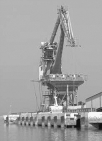
The bucket wheel type barge unloader consists of (Fig. 20.26):

The principle involves a (double) bucket wheel, assembled on a lowerable boom. The bucket-wheels unload the coal from the barge and feed it onto a belt conveyor. The bucket wheel boom can cover the width of the barge by horizontal movement. The barge is pulled by a towing system, so that all areas of the barge can be reached by the bucket wheel. Unloading capacity of up to 4000 t/h of coal can be achieved.
Discontinuous unloading
There is a large range of different types of grab unloaders. In the framework of this chapter, we will look at only those most commonly used for coal unloading:
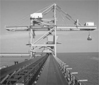
Gantry type ship-unloaders
Gantry type ship-unloaders are common in international ports, as their design is particularly suitable for unloading bulk materials.
Gantry cranes have straight booms, they are non-slewable and the grab moves straight from the hatch of the ship to the hopper. Gantry cranes of up to 85 t for ships up to 400 000 DWT are available in the market. An automatic control system is provided for the grab to ensure precise positioning in the hatch and on top of the hopper (Fig. 20.27).
Double-lever luffing cranes
Double-lever luffing cranes with integrated hoppers are mainly used for dry bulk handling. The crane can also handle general cargo. The cranes with integrated hoppers operate in luffing mode. The grab movements are similar to those of gantry cranes. An automatic control system can be provided for grab luffing. The double-lever luffing crane can slew and, therefore, is more flexible than the gantry unloader; however, it performs at lower operation speeds. Slightly reduced capacities are compensated by multi-purpose functions (Fig. 20.28).
Level luffing cranes
Cranes in this category, also known as multi-purpose cranes, are designed for handling all kinds of material. These cranes can handle, apart from coal and other bulk materials, scrap, boxes of general cargo, and containers using hook, magnet, spreader or grab.
Variations often used in small ports are mobile cranes. Mobile cranes operate independently of any rail system. The operator can position the crane wherever necessary to load or unload cargo or lift something. Once the mobile crane is correctly positioned, it will perform similarly to rail-mounted slewing cranes because the design of what is on top of the turning platform is similar.
The travelling mechanism, however, is different. Rail-mounted slewing cranes are bound to the rail track whereas mobile cranes travel freely. On the other hand, rail-mounted cranes can be repositioned more accurately and faster than mobile cranes.
The above-mentioned cranes are also used for offshore unloading or transshipment, which is a typical operation for stevedoring companies without their own quaysides. Also ships, which are too big to reach the quayside, can be pre-unloaded (please also refer to Section 20.6.1). These ships have to be pre-unloaded offshore to reduce the draft of the ship. Offshore cranes, also named ‘floating cranes’, are generally used for unloading seagoing vessels and the loading of barges, and examples can be seen in Kalimantan, Indonesia, and in Colombia and Venezuela in South America.
For all the above-mentioned types of discontinuous ship-unloaders, the average ship-unloading capacity is between 60% and 65% of the free digging capacity, whereas the free digging capacity is a theoretical capacity and is the only one which determines the real performance of a grab unloader and, therefore, is essential for designing any such machine.
A summary and comparison of discontinuous ship-unloaders follows:
The gantry type ship-unloader is a high performance unloader designed for grab operation only.
The double-lever luffing crane with integrated hopper is slightly lower in capacity, but is designed mostly for grab operation and occasional cargo handling.
Both the level luffing crane and the double-lever luffing crane with separate hoppers are medium performance grab unloaders, very flexible in hand ling cargo.
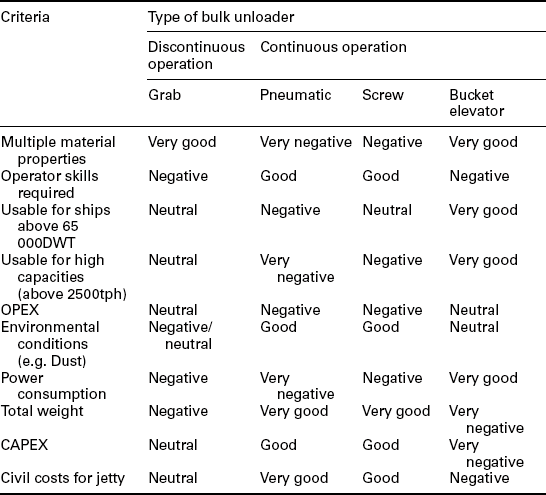
Table 20.4 summarizes the main pros and cons of ship-unloaders. However, it provides only general guidelines, and project-specific requirements will always need to be discussed in detail before a confident selection can be made.
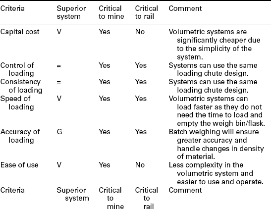
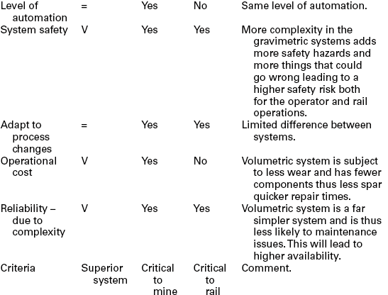
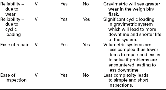
20.4.3 Trainloading
Train load-out stations are the final discharge point at the mine onwards to further process facilities, power plants or port facilities. Typically, two systems are utilized: gravimetric (batch weigh) and volumetric (flood system).
Depending on the application and on the market segment the choice of the system is predetermined. The coal industry typically uses gravimetric (batch) loading (although there are some examples of alternatives) and the iron ore industry typically uses volumetric loading (Fig. 20.29).
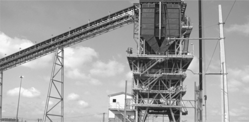
Table 20.5
Main components for train loading stations
| Volumetric system (flood) | Gravimetric system (batch weigh) |
| • Input conveyor | • Input conveyor |
| • Structure | • Structure |
| • Surge bin | • Surge bin |
| • Loading gate | • Surge bin gates (radial, clam and sliding) |
| • Telescopic chute | • Weigh bin |
| • Control room | • Weighing system (load cells) |
| • Hydraulic systems | • Weigh bin gate (radial, clam and sliding) |
| • Control equipment | • Telescopic chute • Control room |
The two above-mentioned systems are further described and compared below to give a better understanding of their differences and applications:
The predominant technology used in the coal in industry is batch loading, mainly due to the ‘easy-to-handle’ and very economical technical approach.
20.5 Crushing stations
The coal coming from the mine (ROM) needs to be crushed to allow further handling. Most of the time, coal is delivered by truck and consists of variable lumps up to 1 m and more in size. In underground mines, the crushing stations are already installed underground to get the material to a conveyable size (approximately < 250 mm).
Most of the subsequent coal preparation requires coal sizes of < 60 mm or even smaller, depending on the process. As such, additional sizing stations need to be installed. The use of roll crushers or sizers is very common, whereas rotary breakers are also still used in some applications, usually where the differential hardness of coal and waste encourages this selection. While it is necessary to crush the coal to a smaller top size, for most of the processes it is also necessary to minimize the amount of fines generated, which are more costly and less efficient to process. Different coal handling options will result in different levels of coal degradation, and this topic is adequately covered in Chapter 9.
The correct allocation of the crushing stations with the right choice of crushing equipment plays a big role nowadays and the discussion about IPCC is becoming of growing interest to mining companies seeking to increase production capacities but reduce equipment fleet size.
The question of mobility of the plant will now be discussed in relation to the fully mobile sizing stations, whereas other ideas around fixed or semimobile crushing stations are covered in a subsequent section.
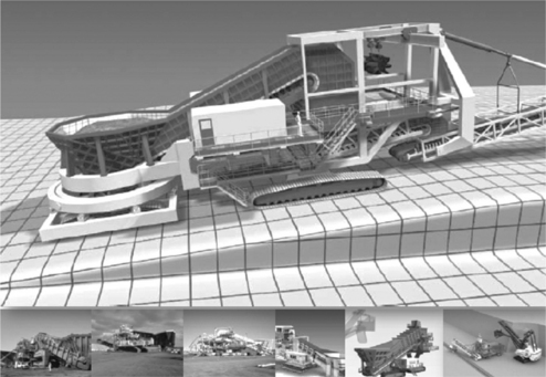
20.5.1 Fully mobile sizing station
In the large-scale fully mobile crushing station world (Fig. 20.30), only a handful of machines have ever been commissioned with capacities that range from 8000 to 12 000 mtph. These are very large machines, with capital costs between 30 and 40 million USD. Within this group of machines, operational success rates have tended to be poor. One significant factor behind this low success rate has to do with the current trend in chassis design. Traditionally, all the equipment manufacturers have elected to design each station with a single fixed car body (generally retrofitted from large rope shovels), suspending the entire machine from a single point on a central slew bearing. Note that only one other manufacturer has developed a multi-track system, to try to improve stability, but still basically utilizes the single point machine pivot on the slew bearing.
These machines have masses in the 1000–1500 tons range and utilize a cantilevered discharge boom of about 25 m. Conversely, a couple of hundred tons of steel and equipment in the form of an apron feeder and hopper are cantilevered opposite the discharge boom – all suspended over one central point. This requires some extreme engineering, with some major risks associated. This cantilevered design is obviously not ideal when used in conjunction with the world’s largest rope shovels dumping 100 tons of material into the hopper from a height of 12 m, not to mention a hopper that already has 300 tons of material in it. This has led manufacturers to design machines that have a luffing style of apron feeder to rest the tail on the ground while in operation. When the machine needs to be relocated (this can be as frequently as every few hours), the operator needs to completely evacuate the machine of any material, raise the apron feeder and hopper with very large hydraulic cylinders, and relocate the machine to match the rope shovel’s new location. This takes significant time out of production, besides requiring massive expenditure in the form of capital costs and in extra steel and mechanicals to make this cantilever system all work together cohesively.
Only a few new companies have entered the mobile crushing arena with some interesting new designs, but these are limited in their mobility aspect because of the configuration of the undercarriage. Geometry always plays a major role when designing these stations. Rope shovels can load only hoppers that have a maximum height of around 8 m, as with any height above that there is simply not enough shovel swing clearance. Compounding this is the fact that each hopper needs to accommodate approximately three shovel dipper volumes for needed surge capacity (300 tons). To keep the hopper at a maximum of 8 m high and hopper walls at 65°–70°, the apron feeder almost needs to sit on the ground to accommodate all this volumetrically. With the apron feeder so low to the ground, this leaves almost no room to install a crawler type suspension underneath.
In the meantime, the market has completed a working concept that will accommodate the afore-mentioned design parameters, with the added benefit of full range mobility while supporting a fully loaded hopper. Moreover, the loading rope shovel can directly load into the hopper without the aid of hydraulic luffing and can follow the shovel path in real time. The design incorporates a unique car body undercarriage that fully supports the apron feeder concentrically with shovel loading. This rear car body also incorporates a unique universal joint suspension to allow the machine to negotiate undulating terrain in all directions up to a maximum of 5% grade. Further, the car body has the freedom of skid steering a full 360°. When combined with a second conventional head car body located directly below the sizer unit, complete mobility is achieved, doing so under operational mode. This gives the machine complete freedom to crawl in all directions, and even to turn on all virtual radiuses, including pivoting the entire machine 360° about the station’s own centre. Included in this high degree of mobility is the fact that the machine is inherently stable. This dramatically reduces operational risk when moving a 1500 tons station from one bench level to the next.
For this new design, the overall height and mass were minimized by borrowing crawler technologies from the heavy lifting crane and crawler transporter industry. These robust track designs are extremely height compact, and not only minimize the overall machine height but also allow for the shortest possible apron feeder design. This is important to note, because the apron feeder can generally be one of the single-most power intensive units on the station. Keeping its overall length to a minimum, as well as minimizing its installed power, is a high design priority. The advent of a compact track system is a key driver in achieving this.
20.6 Auxiliaries
Material handling plants and systems require the machines to work together in one process flow. For that reason it is necessary to also evaluate best possible solutions for additional or auxiliary equipment to work in combination with the above described machines. Some areas are further outlined in the following paragraphs.
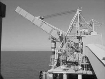
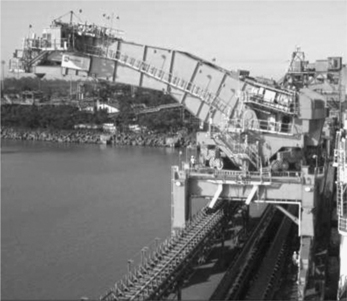
20.6.1 Trans-shipment
The coal industry, both importing and exporting, sometimes requires transshipment of coal from large seagoing coal vessels to smaller barges or vice versa. This trans-shipment is mainly required in areas where only barge access is possible, for example shallow sea waters or where a river leads to/ from a processing plant.
There are several ways of meeting this requirement. One example is the way in which coal is imported to a power plant in Iskenderun, Turkey (Figs 20.31 and 20.32).
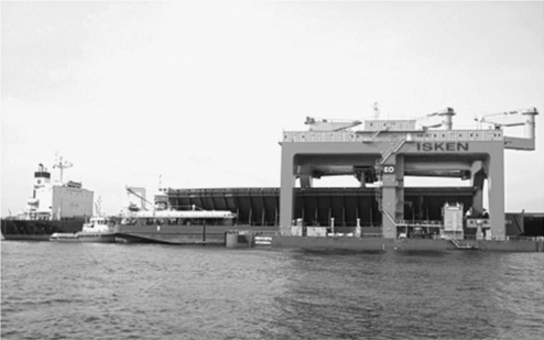
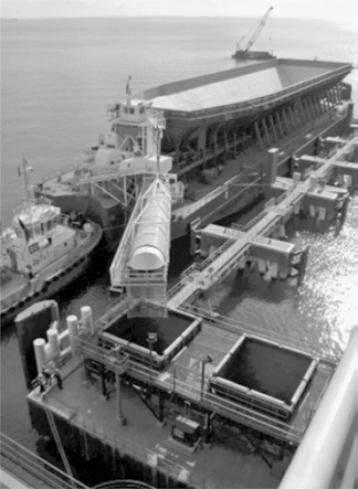
Because the bay of Iskenderun is very shallow in front of the power plant, a different solution is required to unload the seagoing coal vessels (Panamax or Capsize up to 200 000 tons).
A trans-shipper was designed consisting of:
one catamaran with three grab cranes on top (30 000 t/day);
two self-unloading barges, each 10 000 tons load capacity;
three single-point mooring (SPM) buoys to keep the trans-shipper and barges safe during adverse weather conditions.
Similar requirements for other facilities are required all over the world, connecting process plants with sea/river transportation of coal. Again, it is a challenging requirement for materials handling companies to choose the right machinery and the right combination to find the best outcome for the different applications and requirements.
20.6.2 Dedusting and dust suppression
Dedusting and dust suppression are very important parts of the planning of a materials handling plant. Not only will strict environmental rules and regulations define limits of emissions, but the rapidly expanding industry is demanding an increasing environmental awareness, especially in areas of rapid growth such as China, India, etc. Hence, a key focus is to avoid dust emission as much as possible.
Dedusting units, such as filters, are a solution to extract dust from air in transfer chutes, silos, hoppers, and loading and unloading stations. Filters tend to be space consuming and also major power consumers, so an emphasis on good design is essential. Water using dust suppression systems are being mainly used for:
Dust generated during above ground mining and blasting;
Dust generated during and transferring, discharging, crushing and processing;
Dust generated during dumping;
Conveyor belt and product transfer points;
All of the above-mentioned dust suppression and extraction activities are important, but at the same time consume water, wetting agents and polymer binders (chemicals), machinery, power, space and manpower.
Therefore, an integrated engineering approach, involving all specialized engineers from the outset, will allow technical changes to improve overall CAPEX and OPEX of the plants, e.g. chute design with dust settlement zones, different design of discharge and loading areas, avoiding truck traffic by using different technologies (e.g. belt conveyors), fogging systems instead of water sprinklers, and many other solutions can be found to improve the design of coal handling plants.
20.6.3 Defrosting of railway wagons
In cold climates, such as in Russia, China, Mongolia, Canada, USA and others, a defrosting plant for railway wagons may become necessary to be able to defrost and then unload the coal (Table 20.7).
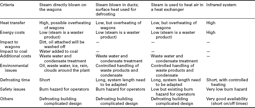
Four main alternatives can be considered for the defrosting of railway wagons:
Chemical pre-treatment on loading using freeze reduction chemicals;
Use of steam directly blown onto the wagons;
Use of steam directed into ducting work: the surface of the ducts is heated and this surface heat is used for defrosting; and
Use of steam directed through a heat exchanger to heat the air.
20.6.4 Electrical and automation
Electrical and plant control systems are an integral part of all materials handling machines and systems. It is important to understand the machine and equipment philosophies to achieve the optimal solution for electrical and automation scope. When it comes to plants and systems, the standardization, and ability to exchange is just as important as in-depth understanding of the equipment itself.
Important issues for the selection of suppliers for electrical and automation are:
Using same interface across the plant;
Built-in process and machine knowledge;
Built-in trending of all available values;
Customized solution built with standard blocks;
Being able to understand trends and changes;
Logging of events and operator actions;
It is important to take an integrated approach when planning the electrical and automation of a machine or plant, i.e. much too often a disjointed approach is taken for bigger plants and the mechanical/structural part of the plant is not planned together with the electrical and automation part.
By applying new and smarter technologies, overall project costs can be lowered. The mechanical and electrical/automation teams need to coordinate efforts exchange early on; even better, companies should combine these levels of expertise in-house, to be able to incorporate developments and better solutions.
Looking at automated materials handling solutions today, the minimum that should be asked for is a coordinated electrical and mechanical design, an individual machine control, central plant supervision, process optimization and, finally, business reporting. Integrated systems with the described functionalities will eliminate the human factor more and more, allow remote control of plants and process, and lower costs through fully automated equipment and plants.
It is worthwhile mentioning examples of fully automated materials handling machinery, which will undoubtedly become widely used in the coming years and will tie in with automated management systems (e.g. stockyard management, and inventory and maintenance management systems). Operator-less and remotely controlled operations are the key words in that respect.
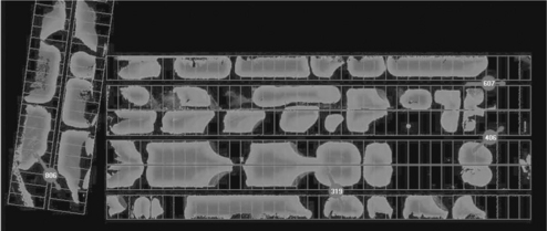
Stacker/reclaimer automated/operator-less system
This system allows for fully automatic no-operator operation of a stacker/ reclaimer in all common modes. A real-time terrain model (Fig. 20.33) makes sure that the system can be effectively used without requiring unproductive scan runs, and ensures a constantly high conveying performance. The high conveying performance is available almost independently of external influences 24/7. In particular, for storage areas working non-stop, it provides a significant potential of rationalization. Furthermore, by precise compliance with limits defined, it reduces wear and tear of the equipment as well as significantly decreasing the probability of damage, through an in-built collision management system.
The described automated system for stockyard machines has proven performance; tests have shown that throughput can be achieved equal to or better than for manual operation. The operation can take place remotely, from a central control room, and up to eight machines can be operated by a single operator.
Similar developments can help in shiploading and unloading activities, and features such as 3D laser scanning, automated positioning, and hatch management (Fig. 20.34) will safely help to lower costs, and improve operational performance, quality and accuracy.
20.6.5 Sampling
In order to guarantee the quality of incoming and outgoing or export and import streams, it is important to know the quality of the product transported. In addition, the correct adaptations of processes need a precise knowledge of raw materials being fed into the process to achieve customer requirements of the finished product.
Sampling is the extraction of a representative volume of predetermined size from the main stream of material at predetermined intervals. In most developed countries there are standards for coal and coke sampling. These standards define the minimum sample mass acceptable and the minimum number of samples to be taken from a consignment, together with other requirements depending on the material being sampled. However, standards do not exist for all materials and differ from industry to industry. Materials handling and sampling companies, and their respective clients, should discuss requirements, conditions and objectives of sampling to achieve the best outcome for a tailor-made design of the sampling plant. This discussion needs to take place at an early planning stage of the plant, and needs to involve adjacent equipment, such as belt conveyors, train loading/shipload- ing, stockyard equipment, etc., in order to define the correct interfaces and battery limits.
For coal the following standards and conditions apply and need to be agreed upon:
Consignment mass/lot size (t);
Required precision – increment variance/prep and testing variance;
In general, three types of samples are taken: chemical, moisture and physical samples. With regard to the chemical sample, the smallest sample may be as little as 200 g, with a particle size of minus 150 micron. This size is normally achieved after a multi-stage sample processing plant. A moisture sample is taken at a point prior to crushing and, consequently, of varying size, depending upon the particle size. A physical sample, on the other hand, may be required for any number of tests, such as sieve analysis, tumble test or shatter test. More details of the sampling aspects are covered in Chapter 5.
Sampling systems are available as fixed open and enclosed stations, or as mobile sampling stations. Most systems today are planned as integrated turnkey systems with a direct link to the plant control system.
Depending on the application online analysers are available as well, which can perform the above-described analytical requirements in series.
Today, in most of the plants, fully automatic sampling (or online analysis) is applied, and even fully automated laboratories are used after the mechanical sampling to get a precise and up-to-date view of the quality of products. This prompt reporting of quality changes can reduce the amount of defective product and lost revenue. Low quality production can often mean extra costs as a result of reworking out-of-specification material.
This technology is being used extensively in various industries but, especially, also in the coal industry, for power generation, shiploading and unloading as well as in the steel industries.
By continuously checking products at various stages of the process and transport points, sampling systems enable plant operators to produce appropriate quality statements, backed by analytical evidence.
Again, proper planning, in line with the planning of the overall materials handling (and processing) plant, is key to a successful design, integration and installation of a sampling system. Today, there are companies in the market that provide this integrated planning approach, instead of just looking at a separate ‘black-box’.
20.7 Conclusion
One of the biggest challenges for materials handling companies is to choose the right machinery, and the correct plant systems, to find the best outcomes for the different applications and requirements. Integrating the design and operational parameters is just as important as making use of all available knowledge, experience and development. It has been proven that cross-referencing between industries is helping to overcome technical issues and problems the industries are facing every day.
The equipment and associated design requirements described in the above chapters should encourage the mining companies to invent, test and accept new designs and approaches to further improve the efficiencies and the cost profiles of the coal industry.
20.8 Bibliography
Paulsen, Anders, Continuous and efficient ship unloading and loading. Proceedings Bulk India. 2003. [paper for].
Nilsen, Arne O., Jacobsen, Paul P., Hopper, Gelnn R., Continual improvement in marine structures and seaboard bulk materials handling design at the Dalrymple Bay Coal Terminal, 2003.
Kuesel, B., The strongest conveyor belts between 1970 to 2003. Proceedings Bulk India. 2003. [paper for].
Velan, B., Bulk terminal operations. Proceedings Bulk India. 2003. [paper for].
Christopher Duffy, Choosing the right ship loader for handling bulk materials, Dry Bulk and Specialist Cargo Handling.
Kaross, Detlef, Isam automation for stockyard machines, 2011.
Frigate, New offshore ship loading facility concept in lightweight construction.
Staribacher, J., The state of the art Pipe Conveyor. Proceedings Bulk India. 2003. [paper for].
Jaap P.J. Ruijgrok, Succesful silostorage (Eurosilo).
Vishwanthan, M., Features of continuous ship unloaders (bucket elevator type). Proceedings Bulk India. 2003. [paper for].
Qi Zaiqiang, A comparison of different designs of bridge grab ship-unloaders, Dry Bulk and Specialist Cargo Handling.
Rainer Borgemann, Ruediger-Wolf Bentjen, Succesful completion of 1320 MW coal-fired power plant Iskenderun.
Morgan, Richard, Bulk Materials Handling Berths, 2011. [Paper and Technical Article.].
Mueller, W., Comparison of international design codes to AS4324.1, 2011.
Kueng, Walter, Semi-mobile crushing plants, 2011.
Knappe, Wolfgang, Port cranes for bulk handling. Proceedings Bulk India. 2003. [paper for].