
Surface chemistry fundamentals in fine coal processing
Abstract:
It is argued that the wettability which is fundamental for flotation also determines the properties of fine coal aqueous suspensions and thus controls not only flotation but also flotation products dewatering and handling either as dry products or as suspensions (e.g. coal-water slurries). Typical fine particle technology problems appear also in gravity separation methods in which fine magnetite aqueous suspensions are used as a medium. In this chapter an attempt is made to look at these various unit operations in some unified way based on the fact the main aspects of these unit operations result from the fundamental fact that all these are aqueous suspensions of fine particles characterized by the same rheological phenomena.
12.1 Surface properties of coal
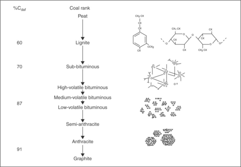
Coal is an organic sedimentary rock whose composition changes with coalification. Since metamorphic development of coal, also referred to as coalification, is synonymous in chemical terms with progressive enrichment of the coal substance in organically bound carbon, all coals, regardless of their origin or type, can be arranged in an ascending order of carbon content (Fig. 12.1). As this figure shows, coal is a highly cross-linked polymer consisting of a number of stable fragments connected by relatively weak crosslinks. Coal also contains heteroatoms, such as oxygen (which appears in coal in the form of phenolic, etheric, and carboxylic groups), nitrogen, and sulfur, and their presence in coal structure strongly affects coal surface properties.
Coal surface properties, like the properties of any other solid, can be studied via wettability measurements. This involves measurement of contact angle (Θ) with the use of liquid with known surface tension (γL).
The work of adhesion of liquid to solid (WSL) is given by
where WSLLW and WSLAB stand for the Lifshits–van der Waals contribution to the work of adhesion and the acid–base interactions energy contribution, respectively (please note that in older publications the term WSLd, the dispersion forces’ contribution, was used instead of WSLLW as is common today).
In order to evaluate the dispersion forces’ contribution to the wettability of coals, Gutierrez-Rodriquez et al. (1984) used methylene iodide and showed that the values of the contact angle measured with this compound do not depend on coal rank, or on its oxidation. These contact angle values for various coals were in the range of 28° ± 9° irrespective of the experimental technique (captive-bubble or sessile-drop).
As shown by Fowkes (1964)
For water γLd ≈ 22 mJ/m2. Methylene iodide, as saturated hydrocarbons, is a useful reference liquid because its intermolecular attraction is entirely due to London dispersion forces. For methylene iodide γLd = γL = 50.8 mJ/m2, and for methylene iodide wetting coal surface, one can obtain:
This gives for coal γsd ≈ 44 mJ/m2.
For coal interacting with water, if it is assumed that coal is a homogenous hydrocarbon matrix that is unoxidized, is mineral matter free, and interacts with water only via dispersion forces:
Putting for water γL = 72 mJ/m2 one can derive the contact angle on such a coal surface would have been about 98°. Any smooth coal surface having a water contact angle of less than 98° contains, therefore, various hydrophilic areas (polar functional groups, inorganic impurities, etc.) on the hydrophobic hydrocarbon matrix (Laskowski, 1994, 2001).
12.1.1 Effect of coal rank on wettability
In the 1940s, Brady and Gauger (1940) observed that the contact angle values measured on Pennsylvania bituminous coals were larger than on anthracite, while North Dakota lignites were very hydrophilic. The results of comprehensive wettability studies on coal from the Donbass Basin (Ukraine) were published by Elyashevich (1941), while further details were provided by Horsley and Smith (1951) in the 1950s. The analysis of the wettability of coals as a function of coal rank was offered by Klassen in his coal flotation monograph (Klassen, 1963) in which he used Elyaschevich’s data. This relationship is shown in Fig. 12.2 using more recent data of coal analysis for oxygen content of Gutierrez-Rodriquez et al. (1984) and Bloom et al. (1957). As Fig. 12.2 shows, low-rank coals that possess a lot of oxygen are quite hydrophilic, while low-volatile matter bituminous coals are the most hydrophobic of all. Comparison of the contact angle values shown in Fig. 12.2 with the calculated value for pure coal organic matrix (about 98°) indicates that while the contact angles measured on bituminous coals are not that different from this calculated value, the difference increases with decreasing coal rank. This is an obvious effect of increasing oxygen content in coal with decreasing rank (also shown in Fig. 12.2). The contact angle measured on bituminous coal is smaller than the calculated values for pure coal organic matrix because coal always contains some hydrophilic inorganic matter (ash).
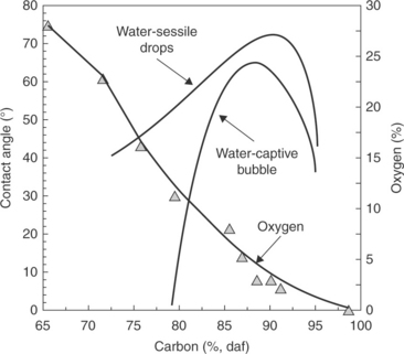
12.2 Relationship between coal rank and wettability by water measured by the captive-bubble and sessile-drop methods, and the relationship between coal rank and the total oxygen content. Source: After Bloom et al., 1957 with permission of Elsevier Source: After Gutierrez-Rodriquez et al., 1984 with permission of Elsevier.
Coal is a very heterogeneous solid. Figure 12.3 is a schematic representation of coal surface. Coal can be depicted as a hydrocarbon matrix that contains various functional groups (Fuersteau et al., 1982). The composition of the matrix varies with the coalification (Fig. 12.1). Coal also contains mineral matter and is porous. As Fig. 12.1 shows, with increasing coalification degree hydrocarbons building coal become more aromatic. Rosenbaum and Fuerstenau (1984) assumed that coal may be modeled as composite material, the non-wettable portions of which are made up of paraffi ns and aromatic hydrocarbons, and whose wettable portions are represented by functional groups and mineral matter. To calculate the contact angle on such a composite surface they used the Cassie-Baxter equation and assumed that the maximum values for contact angles on paraffinic hydrocarbons can be as high as 110°, while those for aromatic hydrocarbons are only 85°. This explains why the wettability of very aromatic anthracites is lower than that of bituminous coals. This concept was further developed in the patchwork assembly model by Keller (1987).
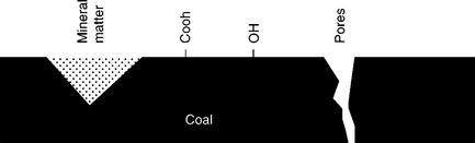
Such an analysis must also include coal porosity. For example, Horsley and Smith (1951) observed that some petrographic constituents (e.g. fusain), lose good natural floatability after prolonged immersion in water. More recent results (He and Laskowski, 1992) entirely prove the effect of porosity. However, while on less hydrophobic surfaces water is sucked into capillaries by capillary forces and this makes such a coal even more hydrophilic, the capillaries on the surface of a hydrophobic coal will stay filled with air and this will make such a surface more hydrophobic.
12.2 Coal flotation
Coal flotation is the only fine coal cleaning process that is effective in treating – 0.15 mm size coal. Because of coal high natural hydrophobicity it may appear to be easy to float, but the wide range of surface properties of coals from various ranks, and various degrees of liberation of the treated particles make the process very often difficult. Flotation of low rank/oxidized coals and desulfurizing flotation are still challenging problems awaiting for solution.
12.2.1 Effect of rank on flotability
In accordance with what has been said, coal floatability should strongly depend on rank as has been extensively discussed (Laskowski, 2001). In 1951, Horsely and Smith concluded that in order to obtain equal recoveries a larger quantity of reagents were required for anthracites and lignites than for bituminous coals. In practice, this requires the use of different combinations of reagents in floating different coals. Xu and Aplan (1993) demonstrated it in a very simple way. Figure 12.4 shows that while MIBC alone is sufficient to float the very hydrophobic bituminous coals, a combination of MIBC (frother) and an oil (collector) is needed to float lower-rank coals. Aplan noted a semi-logarithmic relationship between the fuel oil consumption and the carbon content in coal.
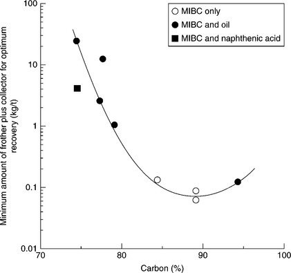
12.4 Minimum amount of frother and collector for optimum recovery of coals of various carbon contents. Source: After Aplan, 1993.
As has already been pointed out, coal is heterogeneous and it contains organic matter and mineral matter. The former appears in the form of macerals, and the latter as minerals. Macerals are classified into three groups: vitrinite, exinite (liptinite) and inertinite. The vitrinite group comprises the most abundant macerals in coal. Macerals do not appear in isolation, but occur in associations in various proportions and with variable amounts of mineral matter to give rise to the characteristic banded or layered character of most coals. These associations are referred to as lithotypes and can be distinguished macroscopically. The lithotypes include vitrain (bright bands in coal), clarain (bright, lustrous constituent, which in contrast to vitrain has dull intercalations), durain (dull) and fusain (black or gray in color with fibrous structure similar to that of charcoal).
Since macerals have different chemical compositions, their surface and flotation properties also vary. As Fig. 12.5 taken from Klassen’s monograph (Klassen, 1963) shows, coal particles varying in size and petrographic composition behave differently in the process. Fine bright particles dominate in the first products and only with time coarse particles and dull constituents start floating. Large particles, including particles that are not liberated, float only when the fine particles are removed from the cell. These data correlate very well with Horsley and Smith’s observations (Horsley and Smith, 1951), which indicate that bright petrographic components (vitrain) are more hydrophobic and float better than dull components (durain).
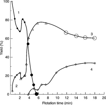
12.5 Effect of petrographic composition and particle size on coal flotation kinetics. (1) bright coal; (2) dull coal; (3) shale interlocked with dull constituents; (4) gangue. Source: After Klassen, 1963.
Arnold and Aplan (1989) claim that hydrophobicity of coal macerals follows the pattern:
exinite > vitrinite > inertinite.
The conclusions regarding the behavior of coal macerals in flotation are further complicated by mineral matter content. The effect of petrographic composition of coal particles on their flotation properties can be studied only for fresh (unoxidized) and low ash samples (Holuszko and Laskowski, 1995). For samples containing more than 15% ash, the surface properties are predominantly determined by mineral matter.
12.2.2 Flotation reagents
The behavior of coal in the flotation process is determined not only by a coal’s natural floatability (hydrophobicity), but also by the acquired floatability resulting from the use of flotation reagents. The general classification of the reagents for coal flotation is shown in Table 12.1 (Laskowski, 2001).
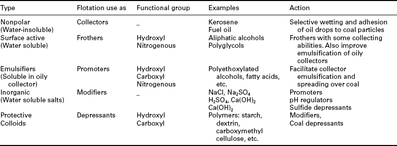
The use of liquid hydrocarbons (‘oils’) as collectors in flotation of coal is characteristic for the group of inherently hydrophobic minerals (graphite, sulfur, molybdenite, talc, coals are classified in this group). Since oily collectors are water-insoluble, they must be dispersed in water to form an emulsion. The feature making emulsion flotation different from conventional flotation is the presence of a collector in the form of oil droplets, which must collide with mineral particles in order to enhance the probability of particle- to-bubble attachment. The process is based on selective wetting: the droplets of oil can adhere only to particles that are to some extent hydrophobic. The effect of emulsification on flotation has been studied, and its beneficial effect on flotation is known (Sun et al., 1955).
Coal flotation is commonly carried out with a combination of an oily collector (e.g. fuel oil) and a frother (e.g. MIBC). All coal flotation systems require the addition of a frother to generate small bubbles and to create a stable froth (Table 12.2). Typical addition rates for frothers are in the order of 0.05–0.3 kg of reagent per tonne of coal feed. Depending on the hydrophobic character of the coal particles, an oily collector such as diesel oil or kerosene may or may not be utilized. When required, dosage rates commonly fall in the range of 0.2–1.0 kg of reagent per tonne of coal feed, although dosage levels up to 2 kg/t or more have been known to be used for some oxidized coals that are difficult to flotate.
Table 12.2
Frothers utilized in coal flotation
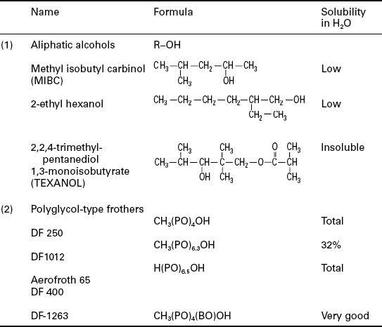
PO stands for propylene oxide (− CH2-CH2-CH2-O-), and BO for butylene oxide (− CH2-CH2-CH2-CH2-O-) Cresylic acids (mixture of cresols and xylenols) that in the past were commonly used in coal flotation are not in use any more because of their toxicity.
The beneficial effect of a frother on flotation with an oily collector was demonstrated and explained by Melik-Gaykazian et al. (1967). Frother adsorbs at the oil/water interface, lowers the oil/water interfacial tension and hence improves emulsification. However, frother also adsorbs at the coal/water interface (Frangiskos et al., 1960; Fuerstenau and Pradip, 1982; Miller et al., 1983) and provides anchorage for the oil droplets to the coal surface. Chander et al. (1994), after studying various non-ionic surfactants, concluded that the flotation of coal can be improved in their presence because of the increased number of droplets, which leads to an increase in the number of droplet-to-coal particle collisions. While the use of oily collectors and frothers is the most common, also a group of flotation agents known as promoters have found application in coal flotation. In general, these are strongly surface-active compounds and are mostly used to enhance further emulsification of water-insoluble oily collectors in water.
Because of environmental concerns associated with tailing ponds, the method for disposing of fine refuse from coal preparation plants by underground injection has been gaining wide acceptance. Unfortunately, many common flotation reagents, including diesel oil, are not permitted when fine refuse is injected underground into old mine works. This is the main driving force for finding replacement for the crude-oil based flotation collectors (Skiles, 2003). An alternative to fuel oil may be biodiesel, a product created by the esterification of free fatty acids generally from soy oil, with an alcohol such as methanol, and subsequent transesterification of remaining triglycerides. Water, glycerol and other undesirable by-products are removed, to produce a product that has physical characteristics similar to diesel oil. The use of some vegetable oils was demonstrated to provide equivalent (and even superior) flotation results when compared with diesel fuel (Skiles, 2003). These are the results of commercial scale tests on a circuit that has 4.25 m in diameter columns. The product concentrate ash was 13.5%. The consumption of the tested vegetable oil was about two times lower from the consumption of diesel oil in these tests.
12.2.3 Flotation of low rank coals
The subject of flotation of low-rank coals was tackled by Wheeler (1994) in his interesting paper on the effect of frothers on coal flotation. Frothers have by far the largest effect on coal recovery and they do not only act in their traditionally accepted function of ‘bubble makers.’ In his tests he used anthracite, medium-volatile bituminous, high-volatile B bituminous, and subbituminous A coals, and different frothers in combination with fuel oil. For easy-to-float medium-volatile bituminous coal the aliphatic alcohols such as MIBC were found to be excellent. Going down in the order of natural floatability, medium-volatile bituminous > anthracite > high-volatile B bituminous > subbituminous A. MIBC quickly loses its effectiveness, first to 2-ethyl hexanol, then to texanol and glycol frothers (e.g. DF-1012). On the bvBb coal 2-EH floated 15% more coal than MIBC. Wheeler’s results confirm that, while short chain aliphatic alcohols possess only frothing properties, other frothers also exhibit collecting properties, and the properties of oil emulsifiers. So, the first conclusion is that in the flotation of lower-rank/oxidized coals, one single reagent is not sufficient. A combination of properly selected frother and an oil, and good emulsification, in most cases leads to a satisfactory flotation. The use of the specifically selected promoters may also be helpful.
The use of properly selected reagents under the best possible conditions is especially important when coals are difficult to process. An emulsification of the reagents and their stage addition are particularly useful in such cases. An obvious practical solution is shown in Fig. 12.6.

12.6 A general concept showing a coal flotation circuit with emulsification of oily collector and stage addition of reagents. Source: After Laskowski, 2001 with permission of Elsevier.
12.2.4 Desulfurizing flotation
The need to reduce the sulfur content of coal to low levels is one of the more pressing needs facing coal preparation engineers if they are to actively assist power-generating stations in reducing their overall sulfur emissions. Yet, as of now, effective pyrite depression for a wide variety of coals remains out of reach.
Coal, a sedimentary organic rock, contains organic matter (macerals) and inorganic matter (minerals). Coal preparation upgrades raw coal by reducing its content of mineral matter; the particles with lower ash content are separated from those with higher ash content. The most common minerals that occur in coal are clay minerals, carbonates (e.g. dolomite, calcite, siderite), oxides (e.g. quartz) and sulfides (e.g. pyrite). The last one is especially important.
Convincing pieces of evidence indicate that most of the mineral matter in coal down to micron grain sizes is indeed a distinct separable phase that can be liberated by fine crushing and grinding. Keller (1984) measured the particle-size distribution of mineral matter obtained by low-temperature ashing of a few samples of coal from the Pittsburgh seam. Most mineral grains were in the size range from 1 to 10 μm, while the rest were coarser than 100 μm. Cleaning these coals by the Otisca-T oil agglomeration process demonstrated that the ash content can be reduced to 1% ash by grinding coal down to a few microns. This indicates that the inherent ash content may be as low as about 1% if coal is finely ground to obtain proper liberation, and then concentrated using a highly selective method.
Sulfur is the constituent of coal that most affects coal marketing. Three types of sulfur in coals can be distinguished by chemical analysis: sulfides (pyrite and marcasite), sulfates (mostly gypsum) and organic sulfur. Organic sulfur in coal appears in different organic compounds, such as thiophenes, sulfides (aliphatic R-S-R and aromatic φ-S-φ and thiols (R-SH and φ-SH). The majority of the organic sulfur in high rank coals is thiophenic (Attar. 1979; Attar and Dupuis, 1981). Typical sulfur analyses of coals from different regions throughout the world set out by Mayers (1977) varied from 0.38% to a high of 5.32%. The pyritic sulfur content of these selected coals varied from a low of 0.09% to a high 3.97%, while the organic sulfur content varied from a low of 0.29% to a high of 2.04%. In general, organic sulfur levels greater than 2% or much less than 0.3% are almost never encountered, and pyritic sulfur contents greater than 4% are also uncommon.
The distinction between inorganic and organic sulfur is of great importance. Inorganic sulfur content in coals can be reduced by physical separation methods. In general, coal and pyrite can be separated either by depressing pyrite and floating coal, or by depressing coal and floating pyrite. But since pyrite density is over 5 g/cm3 and coal density is in the range from 1.3 to 1.5 g/cm3, the rejection of gangue (and thus also pyrite) can be improved by better circuitry and machinery. Gravity separation methods are quite efficient in separating coal particles from pyrite particles. Due to the very high density of pyrite, even very small amounts of pyrite are sufficient to increase the density to a point where the coal particles can be rejected. Therefore, particles containing small amounts of pyrite are more easily rejected by density processes than by surface-based processes such as flotation. However, the efficiency of separation by gravity methods falls rapidly for particles finer than 100 μm. Therefore, coal desulfurization depends critically on pyrite grain size, and hence on the dissemination of pyrite in coal, since only pyrite that is liberated can be separated from coal. Statistical analyses performed by Zitterbart et al. (1985) revealed that the percentage of liberated pyrite is inversely correlated to the mean particle size for several seams. For example, for the Pittsburgh seam coal about 55% of pyrite was liberated after grinding coal down to 50 μm.
Since coal is not ground down to liberation sizes before flotation (as it is done in the case of ores), the flotation feed is a mixture of poorly and well liberated particles. A combination of gravity separators and flotation cells in the same fine coal processing circuit is therefore essential; such combined flowsheets are very characteristic for coal flotation.
In practice, the maximum particle size for coal flotation is generally 28 mesh (0.6 mm) for highly floatable coals. The conditions required to recover coarse particles (i.e., high aeration rates and high reagent dosages) must often be avoided since they also favor the flotation of impurities. Consequently, most coal flotation is applied to minus 100 mesh (0.15 mm) particles as more cost-effective spiral concentrators or multiple stages of water-only cyclones can be used to upgrade the plus 100 mesh (0.15 mm) fractions. In such circuits, the fractions high in sulfur that contain pyrite are rejected with high density reject.
Pyrite almost always appears in polymetallic sulfide ores. Since it is treated as a gangue, which has to be depressed in the differential flotation of sulfides, its floatability has been extensively studied. In the flotation of sulfide ores with thio-collectors (e.g. xanthate), it is common to depress iron sulfides (pyrite/marcasite/pyrrhotite) by carrying out flotation in an alkaline environment using lime. However, similar conditions do not depress pyrite in the flotation of coal (Fig. 12.7). The collector–frother system in coal flotation is dictated by coal rank and floatability, and the selected reagents for best coal flotation apparently also promote pyrite flotation. It is known that some sulfides display so-called self-induced flotation in moderately oxidizing conditions. It is of interest to point out that Baker et al. (1990) observed the synergistic action of coal and oxygen in coal pulps. This mechanism, as well as incomplete liberation from organic matter, may be responsible for the different behaviors of coal-pyrite and ore-pyrite. It is known that coal-pyrite floats well in the presence of hydrocarbon collectors (Olson and Aplan, 1984).
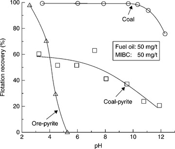
12.7 Comparison of flotation recovery of fine coal, coal-pyrite, and ore-pyrite as a function of pH using fuel oil and MIBC. Coal – 74 μm, coal- and ore-pyrite – 45 μm. Source: After Jiang et al., 1993 with permission of Elsevier.
Since the first option, namely flotation of coal and depression of pyrite has not been very successful, the second option, that is the reverse flotation in which coal is depressed and pyrite is floated, was also investigated. In the ‘two-stage reverse flotation process,’ developed by the US Department of Energy (Miller and Deurboruck, 1982), after the first conventional flotation stage, the froth product that contains coal but also pyrite particles is repulped with dextrin and the pyrite is floated off with xanthate in acidic pH from depressed coal. Although the pilot plant tests were very encouraging, the process has not been commercialized.
12.3 Solid–liquid separation
Unit operations in the coal preparation plant can broadly be divided into four distinct groups: classification (that is mostly screening), beneficiation, dewatering of the beneficiation products, and water clarification (Fig. 12.8).
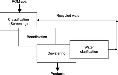
As Figs 12.8 and 12.9 demonstrate, with the exception of screening (and some crushing), all other unit operations are carried out in water. Therefore, what the coal prep plants are dealing with are aqueous suspensions. As the term ‘fine’ indicates, in the fine coal cleaning circuit the solid particles are fine. These fine suspensions, whether flotation froth products or flotation tailings, are subjected to the solid–liquid separation since clarified water must be recycled back to the process. The properties of these suspensions, and our ability to control them, determine the outcome of such unit operations.
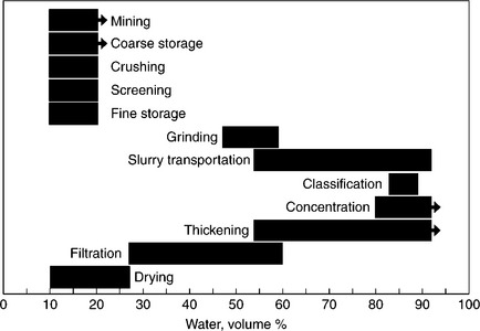
12.9 Variation in water content during various stages of processing (Holland and Apostolides, 1969).
12.3.1 Stability of mineral suspensions
The solid-in-liquid dispersed systems are commonly classified as colloids or suspensions. In the former, the particle size is below 1 μm; in the latter case, these particles are larger than 1 μm. Brownian motion of particles suspended in a liquid, characteristic for colloidal systems, ceases when particles are coarser than 1 μm. However, irrespective of their size, particles suspended in a liquid frequently collide, not only because of their Brownian movement, but also because these particles, depending on their size, settle at different rates. As a result of such particle–particle collisions, the stability of the system is determined by the interaction between the particles during these encounters. The system is considered to be stable when the particles are dispersed and settle as individual units; the system is unstable, and coagulates, when the particles form aggregates and settle quickly.
In the case of colloidal systems, detection of the coagulation is fairly simple. In the case of mineral suspensions, the size of the particles is such that they are not subjected to the Brownian motion and thus the solid particles settle due to gravity (at the rate given by Stokes’ equation). The state of aggregation of such a slurry can be judged by visual inspection of samples left to stand in tall glass cylinders. The typical behavior of A dispersed (stable) or B coagulating (or flocculating) polydisperse and multicomponent slurries is shown schematically in Fig. 12.10.

12.10 Visual appearance of mineral suspensions (schematic). (a) stable; (b) coagulating. (1) initial; (2) short time; (3) long time. Circles: appearance of samples in the optical microscope (Kitchener, 1978).
12.3.2 DLVO theory
In the DLVO theory (developed independently by Deryaguin, Landau, Verwey and Overbeek) the energy of interaction between solid particles is estimated as a sum of the London-van der Waals attraction, and electrostatic repulsion (when the interacting particles have the same either negative or positive electrical charge) resulting from overlap of the electrical double layers surrounding the interacting particles (Fig. 12.11).

12.11 Schematic picture of the two identically charged solid particles which double layers overlap when they approach each other (Gregory, 2006).
In the classical DLVO theory, the total energy of the interaction between two particles is given by
where VR is the energy of electrostatic double layer repulsion (positive value means repulsion) and VA is the van der Waals attraction (negative value means attraction).
In practical situations, the electrokinetic potential (known as zeta potential) is measured to characterize the electrical charge of solid particles. Figure 12.12 shows the calculated value of the total interaction energy (V) for the system at two different values of the zeta potential.
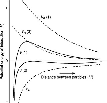
12.12 Total interaction energy obtained by summation of an attraction curve, VA, with two different repulsion curves, VR (Shaw, 1970).
The repulsion between two particles depends on the electrical charge of these particles. Figure 12.12 shows repulsion curves at two different values of zeta potential of the interacting particles. Since zeta potential can be changed, for instance by changing pH, and the van der Waals attraction forces, which depend on the chemical composition of the particles, are not changed when pH is altered, and the two total interaction curves for this system are different. In Case 1, the zeta potential is large and the repulsion curve VR (1) is very positive, giving large positive values of the total interaction curve (the maximum on the total interaction curves is referred to as energy barrier). If the kinetic energy of the interacting particles is not large enough, the particles will not be able to overcome the energy barrier and the particles will not attach to each other. The system will then be stable. In Case 2, the energy barrier does not exist; each collision between the particles leads to attachment, and the system will coagulate. Hence, coagulation is the process in which the particles aggregate when the electrical repulsion between the particles is lower than the energy of attraction.
For particles which are hydrophobic, the attraction energy also includes the hydrophobic force, which is larger than the van der Waals attraction. As shown by Xu and Yoon (1989, 1990), the coagulation curve in such a case looks like that shown in Fig. 12.13 (top part). The experimental curves were obtained for a bituminous coal. Since with increasing hydrophobicity the additional hydrophobic attractive force becomes larger, which together with the van der Waals force is balanced by the electrostatic repulsion dependent on pH, the pH range of coagulation increases with increasing hydrophobicity of the interacting particles.
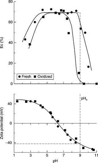
12.13 Effect of pH, and hydrophobicity, on coagulation of fine coal particles. Source: Xu and Yoon, 1989 with permission of Elsevier.
As Fig. 12.14 shows, the iso-electric points of coals (the pH at which the zeta potential values are zero) are more negative for lower-rank and oxidized coals. Such particles acquire more negative zeta potentials in water, are less hydrophobic (Fig. 12.2), and thus form more stable suspensions. Fine coal suspensions of hydrophobic bituminous coals coagulate easily. Honaker et al. (2004) have even shown that the naturally hydrophobic material (such as coal and graphite) can be selectively coagulated and separated from hydrophilic impurities without the use of oily agglomerants and flocculants.
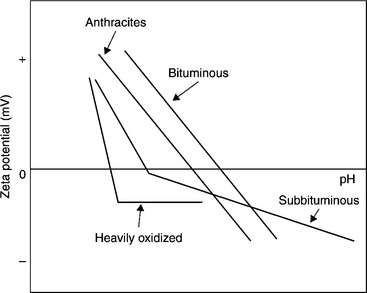
12.14 Generalized zeta potential vs pH diagram for coals of various rank. Source: Laskowski and Parfitt, 1989 with permission of Taylor & Francis.
12.3.3 Flocculation
The merit of modern polymeric flocculants is their ability to produce larger, stronger flocs than those obtained by coagulation. Flocculants are polymers with high molecular weight that are soluble in water. It is generally accepted that polymers used as flocculants aggregate suspensions of fine particles by a bridging mechanism.
The bridging is considered to be a consequence of the adsorption of the segments of the flocculant macromolecules onto the surfaces of more than one particle. Such bridging links the particles into loose flocs (Fig. 12.15).
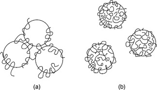
12.15 Schematic illustration of (a) bridging flocculation, (b) restabilization at high concentrations by adsorbed polymer.
The polymers used in flocculation can be classified into coagulants, which are highly charged cationic polyelectrolytes with molecular weights in the 50 000 to 106 daltons range, and flocculants, with molecular weights up to 20 × 106 daltons. It is known that flocculants are not very effective for treating stable suspensions and, as pointed out by Kitchener (1972), the flocculation is much more efficient if the suspension is first destabilized by coagulation. This can be achieved by changing pH or by addition of some inorganic coagulants (e.g. lime or alum). Also, low molecular weight cationic polymers can be used to destabilize suspensions, as most mineral particles in water carry negative electrical charge. In general, the destabilization process is strongly dependent on process water chemistry.
Adsorption of the polymer is generally necessary for flocculation to occur. It is important, however, to realize that adsorption and flocculation are not separate sequential processes, but occur simultaneously (Hogg, 1999). There is general agreement as to the basic mechanism involved in the process; the optimum flocculation occurs at flocculant dosages corresponding to a particle coverage that is significantly less than complete. Incomplete surface coverage ensures that there is sufficient unoccupied surface available on each particle for the adsorption of segments of the flocculant chains during collision of the particles. The bridging takes place at flocculant dosages corresponding to a particle surface coverage that is significantly less than complete, and thus at higher concentrations, the polymers stabilize suspensions by the mechanism referred to as steric stabilization.
Hogg et al. (1993) showed that the appropriate choice of flocculants is determined primarily by chemical factors (mineral composition, solution chemistry, etc.), but the performance of the flocculant depends more on physical variables, such as agitation intensity and the rate of flocculant addition.
Flocculants
The vast majority of commercial flocculants are based on copolymers of acrylic acid and polyacrylamide (also referred to as hydrolyzed polyacrylamide):
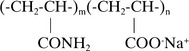
As a result of hydrolysis even ‘non-ionic’ polyacrylamides contain some anionic groups. This is expressed as ‘the degree of anionicity’ (the degree of anionicity of completely hydrolyzed polyacrylamide is 100%, so it is a polyacrylic acid).
Another important group of flocculants is polyethylene oxide, (− CH2CH2O-)n C (Rubio, 1981; Scheiner and Wilemon, 1987). Cationic polyelectrolytes such as copolymers of acrylamide and quaternary ammonium compounds are also available (e.g. Poly-DADMAC). Naturally occurring materials such as polysaccharides (e.g. carboxymethyl cellulose, starch, guar gum, etc.) have also been used as flocculants. According to Kitchener (1978), the first use of flocculants involved the application of starch in combination with lime for the clarification of a coal mine’s effluent (the patent was filed in 1928).
The effectiveness of polymers as flocculants depends on their molecular weight, the sign of their charge (e.g. anionic or cationic), and the relative charge density (for polyacrylamides this is expressed by the degree of anionicity). Depending on molecular weight, the same compounds can operate as dispersants (e.g. dextrin, low molecular weight) or flocculants (e.g. starch, high molecular weight). Low molecular weight copolymers of polyacrylate type are manufactured as dispersants (e.g., Dispex manufactured by Allied Colloids (now CIBA), etc.).
Xu and Cymerman’s (1999) data confirmed that the best flocculants for the clay-containing wastes (Syncrude tailings) are moderately anionic high molecular weight polyacrylamides (optimum around 20–30% anionicity). Hamza et al. (1988) reported that anionic polyacrylamides were the best for enhancing the settling rate of fine coal.
Polymer molecular weight
The molecular weight of flocculants is commonly characterized through viscosity measurements. This is based on the Flory-Huggins (Flory, 1953):
where [η] is the intrinsic viscosity of the polymer solution (has units of reciprocal concentration), M is the polymer molecular weight, and K and a are constants.
After Henderson and Wheatley (1986) Fig. 12.16 shows the effect of polyacrylamide intrinsic viscosity (that is indirectly molecular weight) on the sedimentation rate of flocculated tailings for polyarylamides with varying anionicities.
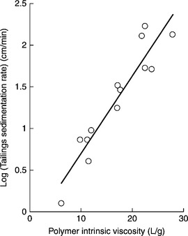
12.16 Effect of polyacrylamide intrinsic viscosity (molecular weight) on sedimentation rate of the flocculated tailings. Source: After Henderson and Wheatley, 1986). Copyright Taylor & Francis Group, LLC. (http://www.taylorandfrancis.com), reproduced with permission.
Because of the relationship between polymer intrinsic viscosity and its molecular weight (Equation [12.7]), what Fig. 12.16 shows is the effect of flocculant molecular weight on flocculation.
It must be born in mind, however, that the intrinsic viscosity of a polymer increases with rising solvent quality. This is shown in Fig. 12.17 for various polymers in various solvents. In a good solvent polymer macromolecules are in extended form, but coil when the solvent quality decreases. This may happen when the ionic strength of the system is increased, or the pH is changed. The exponent a in Equation [12.7] is a measure of the solvent quality and, as Fig. 12.17 shows, it is large (larger than 0.5) for a good solvent, and smaller than 0.5 for poor solvents.
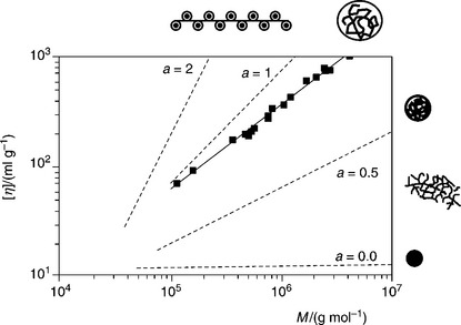
12.17 Intrinsic viscosity [η] as a function of the molar mass Mw for different polymer-solvent systems as given by Eq. [7]. In addition to the straight line relationships indicating the range of good solvents (a > 0.5) and bed solcents (a < 0.5) the experimental curve for polyacrylamide in water at 25 °C ia also shown after Kulicke and Clasen (2004).
Since conformation of polymer macromolecules in solvent depends on the solvent quality, also polymer adsorption onto solid particles depends on it. Adsorption is generally higher from a poor solvent than a good solvent (Koral et al., 1958).
Klein and Conrad (1980) derived the following empirical equation that can be used to determine polyacrylamide molecular weight. This relationship holds for polyacrylamide samples ranging in molecular weight from 5 × 10⁵ daltons to 6 × 10⁶ daltons when measurements are conducted in 0.5 M NaCl solution at 25 °C.
Testing flocculation
Solubilities and rates of dissolution of high molecular weight flocculants in water are generally low, and preparation of the polymer solution is a very important first stage (Brown, 1986). The following step, mixing the polymer solution with the suspension, is critical (Owen et al., 2009).
Since flocculants are either used to enhance solids settling rates to maximize thickener capacity, to enhance dewatering by filtration, or to improve water clarification, various tests are utilized. They include measurements of solids settling rate, sediment density, filtration characteristics, and supernatant turbidity.
Several techniques have been proposed to determine the settling velocity in laboratory experiments, the ‘jar tests’ being the most common (Coe and Clevenger, 1916; Richardson and Zaki, 1954; Michael and Bolgers, 1962). Jar testing involves homogenization of the suspensions in settling cylinders, introduction of the flocculant, and mixing by moving a plunger up and down in the cylinders (or by inverting the cylinders several times). This procedure is claimed not to be satisfactory because of the local over-dosing that can occur when the relatively concentrated flocculant solution meets the slurry (Kitchener 1978); but more important is that the agitation in this method does not produce the optimum flocculation. Farrow and Swift (1996) demonstrated that the jar test has several problems. It is important to realize that adsorption and flocculation are not separate sequential processes, but occur simultaneously (Hogg, 1999). The commonly used improved experimental procedure includes addition of the flocculant to a vigorously agitated suspension, which is immediately stopped after addition of the reagent (Keys and Hogg, 1979). Different mixing/polymer addition conditions may result in very different floc sizes and settling rates. Owen et al. (2009) showed that mixing of the slurry with a dilute flocculant solution within the feedwell determines the performance of commercial thickeners. It was also shown that under certain conditions intense agitation for short times may even change the nature of flocculation, from total flocculation to a selective flocculation of only some mineral constituents (Ding and Laskowski, 2007).
The use of the shear vessel, as described by Farrow and Swift (1996) and Rulyov 1999, 2004), in the flocculation tests was recently tested by Rulyov et al. (2011) and Concha et al. (2012). Their set-up is shown in Fig. 12.18. The use of a shear vessel (similar to rotational Couette viscometers) in assessing flocculation efficiency has the advantage of quantifying the mixing intensity through the shear rate. Using the shear vessel, Rulyov (1999) and Rulyov et al. (2004) have demonstrated that the mixing time in flocculation can be reduced, from minutes to 5–6 s, by the appropriate hydrodynamic treatment of the suspension at a given shear rate. In the set-up shown in Fig. 12.18 the Couette-type vessel is rotating in the external vessel, the gap being 1.5 mm. The reactor is fed continuously with the suspension by a measuring peristaltic pump. Before entering the Couette reactor, the pulp receives continuously a diluted flocculant solution, at a flow rate to give a pre-determined dosage. After 6 s treatment at a pre-determined shear rate in the Couette reactor, the flocculated suspension is discharged from the ultra-flocculator through a 3 [mm] inner diameter transparent tube equipped with an optoelectronic sensor that registers the fluctuation of the intensity of the light beam passing normally through the tube (in accordance with techniques proposed by Gregory and Nelson (1984)). The electronic signal is processed and displayed in a three digital format, thus showing, in relative units, the values of flocculation efficiency (or mean floc size) and the mean shear rate ![]() . In the tests designed to measure the settling rate of the treated suspension, the suspension from the outlet of the tester is continuously fed to a 14 mm diameter settling cylinder and, as soon as the suspension fills the cylinder, the cylinder is inverted once and the initial settling rate is measured.
. In the tests designed to measure the settling rate of the treated suspension, the suspension from the outlet of the tester is continuously fed to a 14 mm diameter settling cylinder and, as soon as the suspension fills the cylinder, the cylinder is inverted once and the initial settling rate is measured.
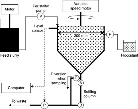
12.18 Schematic illustration of the set-up used to test flocculation. Source: After Concha et al., 2012 with permission of Elsevier.
The flocculation of flotation tailings from one of the major Chilean copper mines and Orifloc-2010 polycarylamide flocculant in a Couette-type reactor was recently reinvestigated by Concha et al. (2012). By varying the shear rate from 100 to 2000 [s−1], the solid concentration from 1 to 15 % by volume, and the flocculant dosage from 0 to 20 g/ton, it was shown that an important interaction exists between these variables. At the optimal flocculant dosage, the optimal suspension concentration and the optimal flocculation time, an increase by 50% in the solid flux density function is possible when the shear rate of ![]() is changed to the optimum value of around
is changed to the optimum value of around ![]() . It is worth pointing out that ultraflocculator-type devices have already been installed at some coal preparation plants (Rulyov, 2004; Rulyov et al., 2009).
. It is worth pointing out that ultraflocculator-type devices have already been installed at some coal preparation plants (Rulyov, 2004; Rulyov et al., 2009).
Testing the use of flocculants in filtration
In present day practice, disposal of the fine waste fraction (for instance, coal flotation tailings) is usually accomplished by:
1. addition of flocculant to the slurry and thickening of the resulting flocs in a thickener, with the underflow from the thickener pumped to an impoundment area;
2. treatment of the thickener underflow with flocculant and dewatering on a mechanical device, such as vacuum filter or filter press.
The former method requires the availability of enough land environmentally suitable for construction of impoundments and, with the latter, the dewatered material can be mixed with coarse waste fraction and discarded by stacking. This latter method requires dewatering by filtration.
The dewatering process during filtration comprises several stages, as illustrated in Fig. 12.19 (Lockhard and Veal, 1996). Flocculants reduce the segregation of fine and ultrafine particles, which causes blinding of the filter medium, and thus increases dewatering rates.
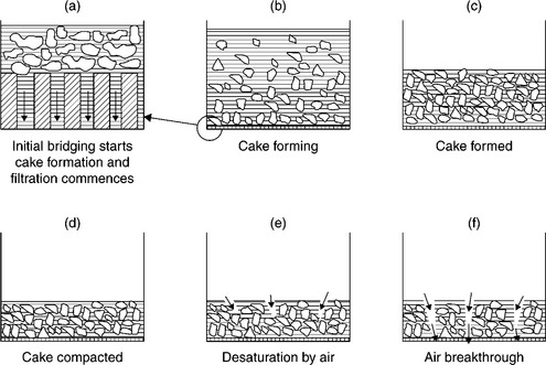
12.19 Schematic representation of stages in dewatering by filtration. Source: After Lokhart and Veal, 1996). Copyright Taylor & Francis Group, LLC.(http://www.taylorandfrancis.com), reproduced with permission.
Experimental determination of the effect of flocculants on filtration usually involves flocculation of the tested slurry, transfer of the flocculated material to a funnel-type filter that is operated under controlled vacuum, and determination of both the filtration rate as well as the cake moisture content. The filtration rate is described by Darcy’s equation:
where dV / dt is the volumetric flow rate of filtrate through a filter cake in time t, A is the filter area, ΔP is the pressure drop across the filter cake, η is the liquid viscosity, H is the cake thickness, and K is the rate constant referred to as permeability.
where ε is the cake porosity, S is the specific surface area of the particles, and k is the Kozeny constant.
The effect of flocculants on the filtration rate is related to changes in filtercake properties; the permeability, which is determined by porosity of the cake, is the most important. As it is determined by particle size and shape, the appearance of the flocs improves the cake porosity. In the simple filtration tests in a funnel-type filter the particles segregate. Figure 12.20 shows a better set-up (Tao et al., 1999), which has been introduced to avoid this problem.
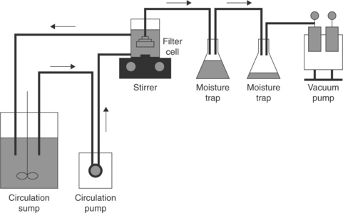
12.20 Illustration of experimental set-up for fine coal dewatering by filtration. Source: After Tao et al., 1999). Copyright Taylor & Francis Group, LLC.(http://www.taylorandfrancis.com), reproduced with permission.
In the device shown in Fig. 12.20, the slurry is continuously circulated to avoid sedimentation and the filter leaf is submerged in well-mixed slurry. The tests allow determination of the filtration rate vs filter-cake thickness, and the cake moisture content vs the filter thickness.
As Fig. 12.19 shows, after the formation of the cake, the cake compression and water expression follow. The situation depicted in Fig. 12.19d is the saturated capillary state, with all the pores filled with water. Under these conditions, a capillary pressure opposes air entry, and only when the applied pressure exceeds the capillary pressure does the removal of water from the cake commence (Hogg, 1995).
where γ is the surface tension of the liquid, Θ is the contact angle at the solid–liquid interface (receding angle should be used).
Equation [12.11] describes the applied pressure necessary to expel liquid from the pores in a packed bed. The equation shows that more hydrophobic coals are easier to dewater, and that the use of surfactants to lower water surface tension may also have some merit. From this point of view, the filtration aids can be classified into:
1. Flocculants (to increase cake porosity and thus filtration rate).
2. Oily hydrocarbons (to make the coal particle more hydrophobic, agglomerate fine particles, and thus increase not only cake porosity but also particle hydrophobicity).
3. Surfactants (to lower water surface tension and thus reduce capillary retention forces).
While polyacrylamide flocculants are commonly used to improve the settling rate, their application in filtration circuits has some specific functions. The use of high molecular weight non-ionic and anionic flocculants shows that there exists a flocculant addition range where there is a significant reduction in the moisture content of the filter cake. Increased polymer addition results in an increased moisture content. This can be explained by different flow modes of liquid through the flocculate filter cake. While the increased flocculation of fine particles may improve the interfloc flow, the drainage of liquid from the flocs becomes increasingly difficult (Mishra, 1987). This suggests that, while at certain doses the cake moisture content can be reduced, it may increase again at high flocculant doses. When moisture reduction is the objective, for high molecular weight polymer, over-dosing can lead to an increase in the moisture content. With low molecular weight polymers, a greater degree of moisture reduction can be achieved (Mishra, 1987). Since flocculants are hydrophilic macromolecules, their adsorption makes solid particles hydrophilic and this also increases the ability of the solid to retain moisture.
Emulsified oil can also be used as a filtration aid. Such emulsion not only agglomerates fine coal particles but also renders them hydrophobic. Nicol and Rayner’s (1980) results demonstrate that an oil addition of 1% can lead to a lowering of the filter-cake moisture from 26% to 16% (wet basis). This considerable lowering of filter-cake moisture is accomplished by an increase in both filtration rate and solids pick-up rate as oil droplets agglomerate fine coal particles. A dramatic improvement in fine coal dewatering with the use of asphalt emulsions was reported by Wen et al. (1994). The effect of flocculants, emulsified oil, and the addition of surfactants on fine coal filtration have been studied by Laskowski and Yu (1998, 2000). They have shown that the emulsification of kerosene in the presence of surfactants can dramatically reduce the size of oil droplets and, more importantly, can entirely change the electrokinetic properties of such droplets. The particles of low-rank/oxidized coals are negatively charged in water and are difficult to agglomerate with oil. However, when the oil is emulsified in solution with a cationic surfactant, the obtained cationic-emulsion agglomerates such a suspension efficiently, improves filtration, and also reduces the cake moisture content. Novel dewatering aids were patented by Yoon and Basilio (U.S. Patent 5,670,056). As pointed out by Yoon et al. (2003, 2006), while the addition of 0.5 kg/t of kerosene could reduce the cake moisture content by 5%, the use of their novel additives was able to reduce the moisture content from 20–30% down to the 8–14% range using vacuum filtration. The improved performance of new hydrophobizing agents has been attributed to a simultaneous decrease in filtrate surface tension and increase in particle hydrophobicity. As disclosed in a patent (U.S. Patent 5,670,056) these new dewatering additives include fatty acid esters; the examples provided indicate that they are mostly used as a solution in butanol. These agents seem to be similar to the EKT agent patented as a coal flotation promoter (Polish Patent 104,569).
Use of flocculants in coal processing
In the most common applications, anionic polyacrylamide flocculants are applied with molecular weight of 106–107 daltons.
While flocculation of coal-clay fine waste generated by coal preparation plants that is then pumped to a pond or impoundment provides a method for rapidly recovering most of the water contained in the waste slurry, this technique also requires the availability of enough land. A method of disposal that minimizes the land requirements is that whereby the underflow from the thickener is treated with a flocculant and dewatered on a mechanical device such as filter or belt press. Such treatment yields a material that can be mixed with the coarse waste fraction and disposed by stacking. However, this technique heavily depends on whether the treated material reslurry during a wet season. As was shown by the US Bureau of Mines (Brown and Scheiner, 1983; Scheiner, 1996), an interesting alternative is the use of polyethylene flocculant (PEO). In the developed process of coal-clay waste flocculation with PEO, addition of calcium or magnesium salts (for instance lime) is required. Their results indicate that prior coagulation before application of PEO is very important for efficient bridging. In this process lime is added up to pH 9 or higher and the PEO dosage required to get optimum results varied from 50 to150 g/t. A dewatering system developed by the US Bureau of Mines uses PEO to flocculate the waste, followed by dewatering on a static screen. The waste is dewatered (using about 0.05 kg/t of PEO) to produce a material having a solid content ranging from 55% to 60%. It is important that the dewatered material is quite stable and does not re-slurry easily when brought into contact with water. Comparison of PEO with PAM (with about 40 Da) in the dewatering of the flocculated coal-clay wastes on a belt filter press showed that the required dosages of PEO were much lower than those with PAM to obtain about 70% solids content.
12.3.4 Oil agglomeration
Insoluble ‘oily’ collectors are utilized in coal flotation. Such oils appear in the pulp in the form of droplets when oil is emulsified in aqueous environment. The droplets attach to the particles that are hydrophobic and then bridge these particles when the system is vigorously stirred. This is so-called oil agglomeration. Three major factors control oil agglomeration (Capes, 1991): (a) solid wettability; (b) the amount of the oil; and (c) the type and intensity of conditioning. The amount of agglomerating oil is critical. At low oil levels, discrete lenses-shaped rings are formed at the points of contact of the particles (Fig. 12.21a and 12.21b). At higher doses, the oil rings begin to coalesce and form a continuous network (Fig. 12.21b and 12.2c).
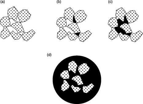
12.21 Oil distribution on moist agglomerates: (a) pendular state; (b) funicular state; (c) capillary state; (d) oil droplets with particles inside or at its surface.
Since droplets of pure aliphatic hydrocarbons attach only to very hydrophobic particles, they are very selective. Droplets of the oils containing polar hydrocarbons can also attach to the high-ash coal particles. This translates into higher yields of the agglomerated product and higher ash content. ‘Heavier’ oils were shown to yield excellent recoveries under the more intense mixing conditions needed to disperse more viscous oil in water (Capes and Germain, 1982; Capes 1991). Fuel oils with addition of aromatic hydrocarbons were found to be very good agglomerants (Agus et al., 1996; Blaschke, 1990). Labuschange (1987) and Good et al. (1994) described how addition of alcohols to oil can improve oil agglomeration.
New light was shed on the mechanism of the oil agglomeration process in a series of papers by Wheelock and his co-workers (Drzymala et al., 1986; Drzymala and Wheelock 1997; Milana et al., 1997). Their results revealed that the agglomeration process of a moderately hydrophobic coal with heptane is triggered by a small amount of air present as a separate phase. The rate of agglomeration increases as more air is admitted to the system, or as the amount of agglomerant or agitation increases.
Oil droplets can attach only to the particles that are hydrophobic, and the oil agglomeration of low-rank, subbituminous coals is not very efficient. Pawlak et al. (1985) reported that subbituminous coals can be agglomerated with heavy refinery residues. Since particles of low-rank coals are charged negatively in water, it was also demonstrated that kerosene with 1% addition of dodecylamine when emulsified in water produces oil droplets charged positively in a very broad pH range that agglomerate subbituminous coal very well (Laskowski and Yu, 2000).
Various oil agglomeration processes have been developed (Mehrotra et al., 1983). These include Trent, Convertol, NRCC (National Research Council of Canada), Shell, Olifloc, CRFI (Central Fuel Research Institute in Dhanbad, India), and BHP processes. In the process developed at the National Research Council in Ottawa (Capes, 1991), the light-oil addition and high-intensity conditioning produces micro-agglomerates, and this is followed by the addition of heavy oil and low-intensity conditioning to produce a handleable product that can be recovered by screening. In the more recent developments, the addition of oil was reduced to a few percent, and this provides better selectivity. In these more recent flowsheets, the high- intensity mixing is followed by a low-intensity mixing, which enables the coal-oil agglomerates to enlarge and strengthen. The agglomerated slurry is then passed to a Vor-Siv screen. The recovered agglomerates are further dewatered in a screen bowl centrifuge. In a final stage, the agglomerates can be further enlarged by pelletization.
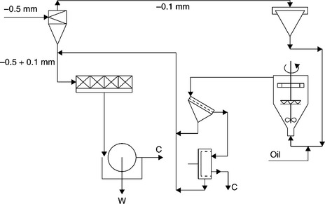
Solid–liquid separation in fine coal cleaning circuits is always difficult (and expensive) and the flowsheet shown in Fig. 12.22 constitutes a very interesting alternative to conventional dewatering and drying. In this process classifying hydrocyclones are used to split the flotation feed into − 0.1 mm and + 0.1 mm fractions. The former is processed by oil agglomeration while the latter goes to flotation. The Oilfolc process offers a means for avoiding thermal drying. The flotation concentrate obtained when floating coarser feed dewatered by vacuum filtration contains 2% less moisture and the oil agglomeration of the fine fraction produces 6–8% ash clean coal products. It is worth noting that such a process can dramatically improve handleability of the final product.
12.3.5 Pelletization
Coal preparation plants rely mostly on gravity separation techniques, and in the past the coarse products constituted main saleable products. Introduction of new separation methods such as flotation resulted in a wide utilization of fine size fractions as well. This in turn has resulted in a considerable increase in the amount of fine clean coal products which poses severe storage, transportation and pollution problems. One possible method by which these problems can be alleviated is pelletization of fine coal.
As reported in literature (Leonard and Newman, 1989; Holuszko and Laskowski, 2010), the addition of a few percent of water to a dry coal can substantially increases its bulk density. This indicates that in the presence of water droplets some sort of consolidation takes place in the bed of fine dry particles. Such a process can be further intensified by tumbling the particles in a disk or drum (pelletization).
The pelletization process is controlled by capillary phenomena, and the driving force for the pelletization is the lowering of the total surface free energy of the system through a reduction of the effective air–water interfacial area. As shown by Kapur and Fuerstenau (1966) and Sastry and Fuerstenau (1977), the kinetics of pellet formation proceed through three stages: the formation of nuclei agglomerates, the transitional stage, and the ball growth stage. The rolling action of the drum brings the individual particle into proximity with each other, so that the physical forces become operative and cause the particles to rearrange, and surface tension reduction brings about nuclei formation via the bridges of wetting liquid. In the agglomeration of granular materials by capillary forces, the wettability of the aggregated particles by the applied liquid plays an important role (Schubert, 1984). Figure 12.23 shows the coal pelletizing circuit (Sastry and Mehrota, 1981).

Only a limited number of research results on pelletization of fine coal are available, and Sastry and Fuerstenau’s EPRI report (1982) is probably the most valuable source of information in this area. Some results of this report will be used to illustrate the principles. Sastry and Fuerstanu (1982) found that it is possible to pelletize coal of different ranks and widely different size distributions. Rive et al. (1964) reported that even coal as coarse as 1.2 mm could be pelletized, provided that it contained at least 50% of − 74-μm material. The rate of the process is governed by the operating conditions and the type of coal. The rate of pellet growth is strongly affected by the amount of feed moisture. The amount of moisture required to pelletize is different for different coal samples, and was found to be mainly determined by the ash content.
Figure 12.24 shows the pelletization results obtained with different samples of raw coal.
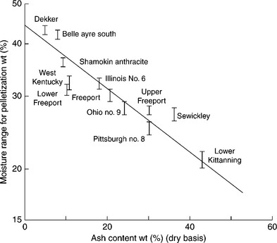
12.24 Influence of ash content (dry basis) of coal samples on their moisture requirements for pelletization. Source: After Sastry and Fuerstenau, 1982.
The coal fines for these experiments were prepared by stage-crushing in a jaw crusher, and dry grinding in a laboratory ball mill. Two hundred gram batches of the dry coal utilized in the pelletization experiments were premixed with the desired amount of distilled water (10 min) to prepare a moist feed. The moist feed was then placed in a 150-mm length by 225-mm diameter pelletizing drum, enclosed in a humidified chamber and tumbled at a rotational speed of 40 rpm. At the end of each experiment, a portion of the pellets was used for determining their moisture content and compressive strength. As Fig. 12.24 demonstrates, pelletization of fine coal is possible only within a narrow range of moisture additions. Outside that range, the coal fines are either too dry to agglomerate or too wet and form lumpy and weak agglomerates. Ash content was found to be the most significant property that determines moisture requirements for pelletization.
Sastry and Fuerstenau’s (1982) report also provided information on the effect of binders on fine coal pelletization. The dry compressive strength of the pellets produced without a binder is from 1 to 10 kg strength. Pellet strength was found to decrease with decreasing ash and sulfur content. Corn starch was found to be a very good binder, in that it improves the compressive strength of the pellets by several hundred percent; however, such pellets exhibit poor resistance to moisture penetration. On the other hand, asphalt emulsion, which was found not to improve pellet qualities much, renders pellets waterproof. The pellets produced with 1% by weight of corn starch that were subsequently sprayed with asphalt emulsion produced strong pellets which were also water resistant.
12.4 Fine coal handleability
The coal must flow by gravity in each operation in the distribution system in order to keep these operations and the whole transportation process efficient. Handleability is commonly defined as the ability of the coal to pass through a handling system without causing blockages and hold-ups (Brown, 1997).
Preparation plants produce coal as blends of various size fractions. Metallurgical coal fines are treated by flotation, and fine coal products are recovered from flotation circuits by filtration. The filter cake commonly has a moisture content in excess of 20%. This, in combination with the rest of the blend, can result in handling problems. In the preparation of thermal coals, untreated fines are usually recombined with the cleaned coarse fractions from wet gravity separation, which also contain a considerable amount of moisture. Many handleability studies carried out over the years have related some of the physical parameters of coal samples, such as amount of fines, mineral matter type, and moisture content, to the handling characteristics.
In the 1950s British coal scientists (Cutress et al., 1960) developed a method to provide a means of assessing the ease of discharge of washed coals and blends from the hopper at the bottom of rail wagons. The Durham Cone test offered a quick and relatively simple way to determine coal flowability. The vibrating cone was designed to imitate train movement (Fig. 12.25); as a result, the behavior of coal during transport by trains could be reproduced using the Durham Cone. Over the years the method became used as the standard test to examine handleability, and was used in many studies with varied success. A first comprehensive study on handleability of coal using Durham Cone was published by Hall and Cutress (1960), and was followed by many others (Vickers, 1982; Mikka and Smitham, 1985; Arnold, 1992; Brown, 1997). The major drawback of the method was that the reproducibility of the results was questionable. It was also pointed out that mixing of the sample before the test was extremely important, and that any mixing involving rolling produced a balling effect and altered the flow properties of the mixture as measured by Durham Cone.
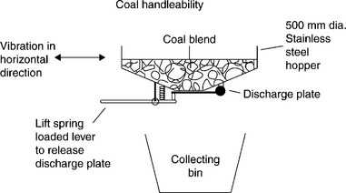
The test results are expressed as Durham Cone Index, DCI = mass sample/average time, or as a flow rate (or Durham Cone discharge rate), with the units being kg/s.
The analysis of the data reported by several researchers failed to detect any simple correlations (Vickers, 1982; Brown et al., 1996). Pretty good correlation was, however, found between the DCI and the product of the simple moisture content and the fines ash fraction, where the fines ash fraction is defined as:
γ0 038 is the weight percent yield of the − 0.038 mm size fraction, Ash0.038 is the ash content in the − 0.038 mm material, and Ashwhole is the ash content in the whole sample.
This correlation is shown in Fig. 12.26 (Brown et al., 1996, 1997, 2000).
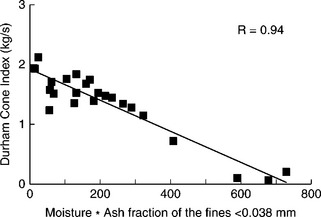
12.26 Durham Cone Index vs moisture x fines ash fraction parameter. Source: After Brown 1997.
Handleability problems can easily be solved by removing wet fines from the power station blend, but this solution is not conducive to maximizing the coal industry saleable output. Better understanding of the factors that control fine coal handleability is vital for finding a long term solution that would allow further dewatering/reconstitution of the filter-cake products into any saleable product.
In the tests described by Jones (1990) it was considered that the reconstitution of the − 0.5 mm size fraction into coarser granules capable of withstanding shear in storage and handling had to be an essential part of any final solution. The results are given in Fig. 12.27. As this figure indicates, the filter cake addition in excess of 8% of the total blend placed the blend handleability below the target level and into the problem zone. By pelletizing the − 0.5 mm fines and adding it in equal parts together with non-pelletized fines the handleability was drastically improved.
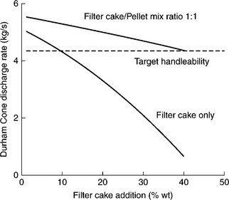
12.27 Durham Cone discharge rate for various percentages of filter cake addition to the power station blend. Source: After Jones, 1990 with the permission of the Mining and Materials Processing Institute of Japan.
Handleability has recently been re-examined and it has been shown that it critically depends on coal surface properties (Holuszko and Laskowski, 2004).
In this research program, pelletizing was used to characterize fine coal tendency to aggregate when it is transported/tumbled.
As Fig. 12.28 shows, depending on coal surface wettability the adhesion of water droplets onto the coal surface will be different. While in the case of weakly hydrophobic (subbituminous or oxidized) coal the water will tend to spread on the surface and strongly bridge coal particles, in the case of very hydrophobic bituminous coal (upper part of Fig. 12.28) the adhesion of the droplets to coal surface will be weak and this will lead to a formation of very frail pellets.
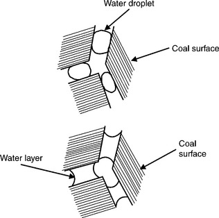
12.28 Schematic illustration of the effect of coal wettability on the behavior of water droplets on coal surface; upper part very hydrophobic bituminous coal, bottom part lower-rank/oxidized coal.
It is rather well established that the content of fines and the moisture content are the most important factors (Wawrzynkiewicz, 2003; Arnold, 2004) determining coal handleability. However, tests on the effect of moisture content clearly indicate that this may be very different depending on coal surface properties. Figure 12.29 shows the flow curves determined with the use of the Durham Cone for two coal samples.
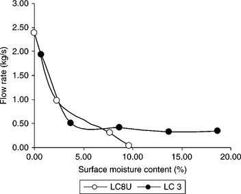
12.29 Durham Cone discharge rate for LC 3 (36% fines) and LC 8U (37% fines) coal samples as a function of surface moisture content. Source: After Holuszko and Laskowski, 2006.
Medium-volatile bituminous coal samples from British Columbia were used in these tests. The oxidation degree of the tested samples was determined using the transmittance measurement of the alkali extracts (ASTM D 5263–93), and their wettability was characterized by the equilibrium moisture (ASTM D 1412–93). The high equilibrium moisture indicates hydrophilic coal, while low (around 1%) moisture indicates hydrophobic coal. The high transmittance values indicate non-oxidized coal (hydrophobic), the values well below 90% pointing to oxidized coal (hydrophilic). The equilibrium moisture for LC 3 sample was 1.30%, while for the LC 8U sample it was 7.34%; the transmittance values for these samples were, respectively, 95.25% and 26.06%.
As Fig. 12.29 shows, the flowrate patterns for hydrophobic LC 3 and hydrophilic LC 8U are different. The flow rates were plotted vs surface moisture for these samples. The surface moisture was obtained as the difference between actual moisture content of the sample and its equilibrium moisture. It can be noticed that at the same amount of surface moisture, e.g. at 10% surface moisture (Fig. 12.29), the LC 8U coal sample ceases to flow, while the LC 3 coal is still handleable.
For lower-rank and oxidized coals, the equilibrium moisture is usually much higher than for high rank and non-oxidized coals. Therefore, these coals can tolerate higher moisture levels before they become difficult to handle. However, at moisture levels exceeding their equilibrium moistures, a rapid deterioration of their handling behavior is observed, leading to practically non-flowing conditions. In the case of hydrophobic coals, only the mineral matter affects handleability significantly. For such coals, an increase in moisture content tends to affect handleability to a certain level, but these coals do not cease to flow completely. Apparently a high amount of clay material, even in very hydrophobic coals, can have a very damaging effect on handleability. These effects can also be tested using pelletization experiments, as it was shown that coals that can easily be pelletized may become difficult to handle at a given level of moisture (Holuszko and Laskowski, 2004).
The picture that emerges from the discussed available results indicates that whenever fine coal particles are ready to aggregate (as a result of their surface properties and the moisture content) they will make the whole blend of various saleable size fractions aggregate, and that will cause handleability problems. The readiness of such a material to aggregate is what creates the problem and this ‘readiness degree’ can be ‘discharged’ only by either rendering such particles more hydrophobic, or by allowing them to aggregate by pelletizing this material.
12.5 Rheology effects in fine coal processing
The importance of this topic has further increased with introduction of coal- water slurries as another way of fine coal utilization.
12.5.1 Viscosity of suspensions
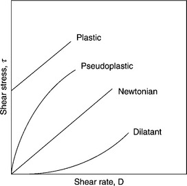
The viscous nature of the fluid, i.e. its internal friction, is manifested only when one region of the fluid moves relative to another. The measurements may involve the flow of liquid through capillary under a given pressure, or movement of the liquid placed in between two cylinders (Couette) and caused by the rotation of one of them. In all such cases, the liquid flow rate (shear rate) is related to the applied shear stress (pressure) via Newton’s low of viscosity:
where τ is the shear stress (Pa), η is the dynamic viscosity (Pa · s, Pascal second = Nm−2 s), and D is the shear rate (s−1). In the old system a convenient measure was the centipoise (cP = 0.01 poise), because water has a viscosity of about 1 cP at room temperature (on the SI scale this corresponds to 1 mPa · s).
Figure 12.30 is a sketch of the shear stress vs shear rate relationship for several different fluids.
For a stable (no aggregation) diluted suspension of solid spherical particles in Newtonian liquid, Einstein derived the following expression
where η is the viscosity of the suspension, ηos is the viscosity of the suspending medium and φ is the volume fraction of the suspended solid particles.
Rheological measurements, when relative viscosity (relative viscosity = η/ ηo) is plotted vs solid concentration (usually v/v %), provide the curve displayed in Fig. 12.31. As this plot demonstrates, the viscosity of a suspension of spherical particles significantly deviates from Einstein’s law above φ = 01, and beyond a volume fraction, φmax, called the maximum packing fraction, the dispersed particles lock into a rigid structure and flow ceases. The packing fraction for hexagonally packed monodisperse spheres is 0.74. As pointed out by Barnes et al. (1989), these values are much smaller for other particles (only 0.3 for grains, and 0.2 for rods).
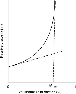
12.31 Schematic graph showing the concentration dependence of the relative viscosity of a typical suspension. The slope at the origin equal intrinsic viscosity.
The relative viscosity function depicted in Fig. 12.31 in the dilute region is determined by the requirement that the slope at the origin equals the intrinsic viscosity (2.5 for spheres). The function is best described by the Krieger–Dougherty equation (Krieger and Dougherty, 1959; Kierger, 1972):
where ηr is the relative viscosity, η is the viscosity of suspension/colloid, ηo is the viscosity of suspending medium, φ is the volume fraction of the solid, φmax is the maximum packing fraction, and [η] is the intrinsic viscosity.
Taking [η] = 2.5 and φmax = 0.74 for close-packed uniform spheres the exponent in Equation [12.13] is 2.5 × 0.74 = 1.85. The value of [η] for non-spherical particles is much larger than 2.5.
The rheology of fine particle systems depends on many factors: particle size, shape and solids concentration. Another factor that strongly influences rheological behavior is particle–particle interaction. In general, rheologi- cal behavior becomes more non-Newtonian as the particle size decreases. While well-dispersed systems of spherical particles at low-to-moderate solid concentration (below 40%) exhibit Newtonian behavior, the aggregating systems are non-Newtonian. As Equation [12.13] indicates, the measured relative viscosity becomes very large when φ is near to the close-pack condition and the effect of the factors discussed above becomes particularly evident in this high solid content range. The utility of the Krieger–Dougherty equation is in the fact that it takes into account the effect of particle-size distribution and particle shape, as both affect the maximum packing fraction.
12.5.2 Coal-water slurries (CWS)
Typically coal that has been mined and cleaned in a coal preparation plant is shipped either to a power generation plant (thermal coal) or to a coke-making plant (metallurgical coal). This needs large areas for dry sample storage, handling, and transportation, and poses all sorts of environmental problems (e.g. dusting, spontaneous combustion, etc.).
Coal–water slurries (CWS) (also referred to as coal–water fuels (CWF), or as coal-water mixtures (CWM)) are highly loaded suspensions of fine coal in water. Since these are mixtures of coal and water, CWS is free from some of the major problems of solid coal, such as dusting and spontaneous combustion during storage and transportation. Unlike solid coal, CWS is a liquid, so it does not require large handling facilities. Utilization of fine coal in the form of CWS also simplifies the fine coal preparation circuit, in that it does not need deep dewatering and drying. The fine coal in a filter cake is directly converted into CWS and is pipelined to a power-generating plant, where it is burned like a heavy oil; the coarse coal does not have to be blended with the troublesome fines and so its handling is improved as well.
Since CWS is utilized as a fuel to generate power, its calorific value is an important factor. Because of the loss of energy on water evaporation (latent heat of evaporation for water is about 2300 kJ/kg) the presence of water in CWS reduces its heating value. For instance, for one kilogram of CWS containing 60% of bituminous high-volatile coal with a heating value of 27 MJ/ kg, the simplified calculation gives:
Of course, the evaporative heat loss can be reduced by increasing coal content in the CWS as shown in Fig. 12.32. For a highly loaded CWS with 70% coal the minimum evaporative heat loss will be about 3.65% for highvolatile bituminous coal (27 MJ/kg), and 4.9% for subbituminous coal (20 MJ/kg). However, the most important requirement for the CWS is that it must be pumpable. Consequently the problem is how to increase solids concentration in CWS without raising viscosity above an acceptable level. The answer to this question has two components: (i) the effect of coal particle size and particle-size distribution, and (ii) the effect of coal surface properties and chemical additives (referred to as viscosity reducers).
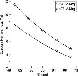
12.32 Effect of coal content in CWS and coal heating value on evaporative heat loss during combustion of CWS. Source: After Laskowski, 2001 with permission of Elsevier.
Effect of coal particle-size distribution on rheology of CWS
The maximum packing fraction, φmax in Equation [12.13], increases with increasing polydispersity of the suspension. Broader particle size distributions have higher values of φmax because the small particles fit into the gaps between the larger ones. On the other hand, non-spherical particles lead to poorer space-filling and hence lower φmax. Particle aggregation, for example flocculation, also leads to a low maximum packing fraction because, in general, the flocs are not close-packed. This was experimentally confirmed by Farris (1968). Since coal content in CWS is the most important factor determining its utility, the effect of the coal particle-size distribution on the rheology of CWS was thoroughly examined.
The top particle size in CWS is determined by boiler requirements; on the other hand, the size and the yield of the fines fractions are determined by CWS viscosity and grinding cost. Because of the burning process limitations, it is usually assumed that the top size cannot exceed 250 μm with a particle- size distribution of 70–80% below 75 μm. With these limits in mind, Ferrini et al. (1984) showed how the coal particle-size distribution could be optimized with regards to viscosity of the highly loaded CWS. Figure 12.33 shows particle-size distribution of the samples tested by Ferrini et al. (1984).
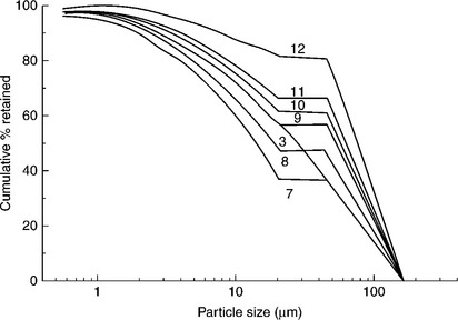
12.33 Particle-size distribution of a family of bimodal particle samples derived from the continuous reference curve No. 3. Source: After Ferrini et al., 1984.
Curve 3 in Fig. 12.33 shows the particle-size distribution of the sample prepared by grinding. The bimodal suspensions were prepared by screening − 20 μm and + 45 μm size fractions from this sample and mixing them at different ratios. Apparent viscosity for the samples varying in particle-size distribution is shown in Fig. 12.34. As this figure demonstrates, the changes in viscosity with particle-size distribution are quite dramatic. Samples 9, 10, and 11, that is the samples that contain about 40% of the fine fraction, have much lower viscosities than Sample 3.

12.34 Effect of − 20 μm fraction content on apparent viscosity of bimodal coal-water slurries at constant overall coal content (72% by wt.). Source: After Ferrini et al., 1984.
Ferrini et al.’s (1984) results clearly demonstrate that a highly loaded CWS can be obtained only by properly adjusting the coal size distribution. The beneficial effects that can be obtained by manipulating the particle- size distribution are considerable, and therefore grinding and selection of optimum particle-size distribution is an import aspect in all CWS-patented technologies.
The Chinese authors (Zhang Rong-Zen et al., 1984; Zuna Wang et al., 1993) claim that the Chinese experience indicates that if a fine coal is unsuitable in its as-received form for CWS preparation, in most cases this is due to low content of ultrafine particles.
Effect of coal surface properties on rheology of CWS
Rheology of fine particle systems depends on many factors, particle–particle interactions being one of them. As shown by Xu and Yoon (1989, 1990), hydrophobic particles tend to coagulate in aqueous environment (Fig. 12.13). We studied such effects with the use of rheological methods.
The tests were carried out with F4 sample of a bituminous coal (ash 11.7%, moisture 0.6%, fixed carbon d.m.m.f 73.3%) from a mine in British Columbia. The contact angle measurements used to characterize its wettability by water gave 90° (advancing contact angle). The suspensions were prepared after dry pulverization of the sample below 212 μm and all the rheological tests were carried out at 59% solids by wt.
As Fig. 12.35 reveals, for the suspensions prepared from the fresh F4 coal sample, very high yield stress values were obtained over a very broad pH range (from about 4 to 9). For the sample oxidized at 85–90 °C over 24 h, high yield stress values were recorded only around pH of 4.5, while for the sample oxidized over 221 h, the yield stress maximum is obviously situated at pH much lower than 3.5. The point is that the iso-electric points for these three samples were found to be at pH 8 for the fresh sample, around pH of 4.5 for the sample oxidized for 24 h, and at pH of 2.5 for the heavily oxidized sample. Thus, while the hydrophobic fresh sample coagulates over a broad pH range from about 4 to 9 (Fig. 12.35) and it is not much affected by the position of the iso-electric point (i.e.p.), the oxidized sample (24 h) coagulates only around its i.e.p. The heavily oxidized sample has i.e.p. around pH 2.5 and it can be expected that the maximum coagulation pH is also situated around this pH value. This agrees remarkably with the data published by Xu and Yoon (1989, 1990).
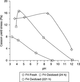
12.35 Yield stress values for aqueous suspensions of the bituminous coal as a function of pH. Source: After Melo et al., 2004, with permission of the Metallurgical Society of CIM.
In the rheological measurements, whenever suspended particles coagulate and the network of the interacting particles is formed, high yield stress values are recorded. The maximum values correspond well with the maximum coagulation (Johnson et al., 2000). While strongly hydrophobic particles coagulate over a broad pH range (see Fig. 12.13), the hydrophilic particles coagulate only over the pH range at which these particles do not carry electrical charge.
In total agreement with these conclusions are our rheological measurements carried out with CWS prepared from the same F4 bituminous coal in the presence of humic acids.
Some of these results are shown in Fig. 12.36. Direct measurements of the wettability of the tested coal in the presence of humic acid indicate that this hydrophobic bituminous coal becomes hydrophilic as a result of humic acid adsorption. This is not surprising, as humic acids are hydrophilic polymers. This compound resulting from oxidation of organic matter, or obtained directly by extraction of low-rank coals, is a complex anionic polyelectrolyte that contains both carboxylic and phenolic functional groups. There is evidence that irrespective of the original coal surface properties, humic acids impart properties similar to low-rank coals to all coals (Laskowski, 2001). The electrokinetic measurements revealed that the coal particles in the humic acids solutions acquire a very negative charge, as evidenced by very negative zeta potential values (almost − 70 mV) (Pawlik et al., 1997). The increased hydrophilicity of coal particles and their increased negative charge must stabilize such particles against coagulation. As a result, the rheological properties of such suspension become more Newtonian, as indicated by decreasing values of the yield stress.
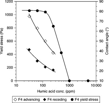
12.36 Effect of humic acids on wettability of bituminous coal and on the yield stress of 65% (wt.) CWS prepared from this coal. Source: After Pawlik et al., 1997 with permission of the Metallurgical Society of CIM.
Coals varying in rank differ in surface properties. While bituminous coals are quite hydrophobic, the subbituminous coals are not (Fig. 12.2). The rheological measurements depicted in Figs 12.35 and 12.36 indicate that these differences in surface properties must affect the rheological properties of the suspensions prepared from such coals. Since hydrophobic solid particles suspended in aqueous environment tend to aggregate, the rheological properties of such suspensions should be different from the rheological properties of the suspensions prepared from low-rank coals.
Figure 12.37 shows, after Schwartz (1985), the apparent viscosity of the coal–water slurry prepared using three different coal samples. This figure indicates that while it is possible to obtain highly loaded CWS from Coal 3 (76% wt.) at the limiting viscosity of 1000 mPa.s, for Coal 1 the maximum solids content at this viscosity is only about 65%. The wettability tests gave for the three coal samples the following contact angles: 90° for Sample 3, 40° for Sample 2, and 20° for Sample 1. These samples were also characterized by chemical analyses that gave the following C/O contents: 4.6 (Sample 1), 12.7 (Sample 2), and 20.8 (Sample 3), with the following contents of C/H: 13.6 (Sample 1), 15.8 (Sample 2), and 18.5 (Sample 3). These results reveal that while Sample 3 is a very hydrophobic bituminous coal, the other two samples were clearly less hydrophobic, with Sample 1 being a low-rank sub- bituminous coal.
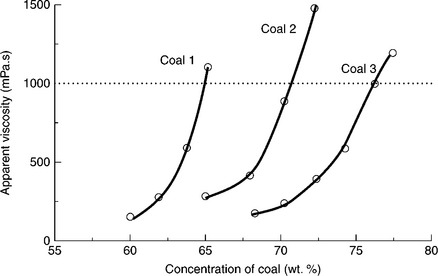
12.37 Apparent viscosity of coal-water slurry prepared from three different coal samples with the same stabilizer (0.05% of non-ionic ethylene oxide/propylene oxide copolymer). Source: After Schwartz, 1985.
Figure 12.37 illustrates well the existing controversy. As is seen from this figure, much higher coal content (loading) can be achieved with higherrank coals than with low-rank coals, and this is sometimes interpreted that it is easier to prepare CWS from high rank coal. The problem is that coal is highly porous and heterogeneous. Coal moisture content (equilibrium moisture) is a function of coal rank. While it is very low for bituminous coals (around 1%) it can be as high as 20% for subbituminous coals. Since the maximum packing fraction, φmax, is around 0.75, the minimum content of water in suspension must be at least 25%. This is needed as water is a ‘lubricating’ medium, without which this fine particle system cannot behave as a fluid. For a low-rank coal, containing 20% equilibrium moisture (coal internal moisture), the minimum content of water is then around 45%, while for the bituminous coal this can be around 26%. Since water content in CWS is the most important factor that determines its calorific value, a few processes have been developed to reduce the ‘internal’ water content in the low-rank coals used in the preparation of CWS.
Figure 12.38 shows apparent viscosity of CWS, measured at a shear rate of 100 s− 1, prepared from six different coals. In all cases, 1% of the same nonionic additive was utilized. Several conclusions are evident from these plots. First, the experimentally measured apparent viscosity dramatically increases at a given solids content, and second, this limiting solids content is different for different coals. Since the particle-size distributions of these samples were similar, the conclusion is that the rheology of CWS depends on coal surface properties. Seki et al. (1985) derived the following relationship:
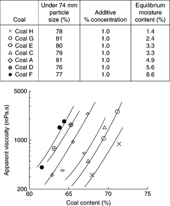
12.38 Relation between apparent viscosity and coal content in CWS for different coals. Non-ionic additive 1% on dry coal basis. Source: After Seki et al., 1985.
where Mf is the free water in CWS, Cc is the dry coal content in CWS, and Mc is the coal equilibrium moisture content.
So, obviously, for a highly loaded CWS (large Cc in Equation [12.14]), the free water content will sharply decrease if the coal moisture content is high, and this will raise the viscosity of CWS. The relationship between coal content in CWS at a viscosity of 1000 mPa.s and coal equilibrium moisture content is shown in Fig. 12.39.
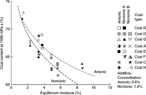
12.39 Relation between coal content in CWS at 100 mPa.s and coal equilibrium moisture. Source: After Seki et al., 1985.
As these results demonstrate, the rheological properties of CWSs prepared from different coals characterized by similar particle-size distributions can be correlated with the coal moisture content, and then coal rank. The relationship between the CWS viscosity and coal moisture content can be used to estimate CWS’s slurryability (maximum coal content in the CWS) at an acceptable viscosity.
Additives in preparation of CWS
CWS must be pumpable and this requirement translates into sufficiently low viscosity, but CWS may be stored in tanks over a long period of time, and thus must also exhibit sufficient sedimentation stability. Different additives are required to reduce viscosity and to increase stability.
Dispersants. Many low molecular weight polymers (MW < 100 000 daltons) adsorb onto coal surfaces and can be used as dispersants for coal–water suspensions. All good coal dispersants are also very efficient depressants for coal flotation (Pawlik, 2005). Both anionic (e.g., carboxym-ethyl cellulose, humic acid, polystyrene sulfonate, etc.) and non-ionic (dextrin) depress coal flotation and, by dispersing coal particles, improve CWS’s stability. According to Hara et al. (1992), while good stability requires steric stabilization, a good slurryability requires strong electrostatic stabilization. Figure 12.40 depicts the effect of dispersant concentration on the viscosity of CWS prepared from three different coals (Higashitani et al., 1990).
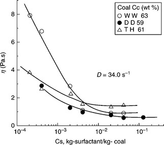
12.40 Effect of concentration of sodium salt of naphthalene formaldehyde sulfonate on CWS apparent viscosity at 34 s−1. Symbols WW, DD and TH stand for different coal samples. Source: After Higashitani et al., 1990 with permission of the Mining and Materials Processing Institute of Japan.
As Fig. 12.40 shows, the CWS viscosity can clearly be reduced only at rather high dosages of dispersants (around 1000 g/t). Yoshihara (1999) synthesized graft copolymers and tested their effect on CWS rheology. The graft copolymers of sodium polyacrylic acid with polystyrene side chain showed higher adsorption onto coal and turned out to be better viscosity reducers for CWS. Polystyrene sulfonate (PPS) with molecular weight of 14 000 is commercially used in Japan for the preparation of CWS.
Additives stabilizing CWS against settling (anti-settling additives). CWSs are made of relatively coarse particles. Such particles tend to settle under gravity and, when stabilized against aggregation, settle as individual particles and form a compact sediment that may be difficult to redisperse. Since CWSs may be stored in tanks over a considerable period of time, such a system must therefore also be stabilized against settling. Figure 12.41 shows schematically how the effect of the structure that develops as a result of particle–particle interactions affects the rheology and stability of CWSs.
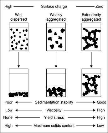
12.41 Illustration of concentrated suspensions showing that at a given solid’s content the volume of sediment depends on particle aggregation. Source: After Laskowski and Parfitt, 1989 with permission of Taylor & Francis.
First, it must be borne in mind that the properties of CWSs are very different from the properties of the disperse systems dealt with by colloid chemistry. The most obvious difference is the solid content. While in a very dilute disperse system any aggregation between particles results in a loss of stability and fast sedimentation, in a heavily loaded suspension the aggregation may prevent particles from settling and so it may stabilize the system. But aggregation creates a network of interacting particles, and this will increase viscosity. Therefore, it is obvious that particles in CWS must be properly dispersed to reduce viscosity, and to increase maximum packing density. Dispersants are used for this reason. But since CWS must also be stable, some weak aggregation will also be required. This is achieved with the use of high molecular weight polyelectrolytes (for instance various natural gums with MW > 106) (Saeki et al., 1999).
CWS from low-rank coals
There are many deposits of subbituminous coals and lignites that can easily be recovered by strip mining. Very often these coals constitute a very attractive ‘clean’ energy source, since they may contain 0.2% sulfur and 8% ash (e.g. Alaskan low-rank coals). However, the high inherent moisture content of these coals and their low heating value on an as-mined basis compromise the economics for rail haulage. Consequently, most low-rank coals are consumed by electric utilities located near mines sites.
In an effort to upgrade coal and produce a transportable fuel, several dewatering processes have been developed. Almost all of the coal-inherent moisture content can be removed by thermal drying; the final moisture content achieved in the product is dependent on particle size and residence time. However, since low-rank coals depreciate due to shrinkage and loss of structural elasticity when they are dried in hot gases, the dried product is dusty and is subject to spontaneous combustion. When the dried coal is slurried in water, a significant portion of the coal moisture removed during drying is reabsorbed onto coal particles. Such slurries have only slightly higher energy densities than similar slurries made from raw coals (usually less than 11.6 MJ/kg (Potas et al., 1986)). To minimize moisture reabsorption, the dried coal can be coated with a fuel oil or can be briquetted.
Many so-called low-rank coal (LRC) drying processes have been developed (Willson et al., 1997). In one such process, the hot-water drying process (HWD), coal is heated under pressure in water. Under such conditions, evolving tars remain on the coal surface and plug micropore entrances. The results shown for a subbituminous coal C from No. 4 seam of Usibelli Coal Mine, Alaska, confirm the very strong effect of temperature on the process; equilibrium moisture content decreases from 25% down to 9.5%, and calorific value increases from 27.3 mJ/kg to almost 31 MJ/kg when the process temperature is increased from 275 °C to 325 °C (Walsh et al., 1993). Ohki et al. (1999) used FTIR spectroscopy and showed that in the processing of an Indonesian LRC, Adaro (16.42% moisture, 45.6% volatile matter, 1.24% ash, 36.74% FC on as-received basis), the oxygen content of coal was significantly reduced.
This results from decomposition of carboxylic groups (and any reduction in the content of oxygen in coal translates into lower equilibrium moisture content). Potas et al. (1986) demonstrated that the maximum solids content in the CWS prepared from two Alaskan coal samples (lignite and subbitu- minous) can be increased from the 45% range to about 55–60% range.
In the vacuum drying/tar coating method (Usui et al., 1999) the coal is dried under vacuum at 200 °C, then at 270–350 °C and is coated with tar (5% wt./coal), and it is used to prepare CWS.
Coal reverse flotation
Bituminous coals are hydrophobic (see Fig. 12.2), float easily, and therefore forward flotation is a common practice. But since subbituminous coals, and also the coals stored in old tailings ponds, which are not that hydrophobic, are difficult to float the reverse flotation may be quite an attractive option in such cases. The reverse flotation of coal has recently been shown to be possible (Ding and Laskowski, 2006).
There are fundamental differences between the forward and reverse coal flotation. In the case of the forward flotation, the clean coal is recovered as a froth product that is made hydrophobic with the use of various flotation reagents. In the case of reverse flotation, the clean coal product is what is ending up in the flotation tailings; this product is kept as hydrophilic as possible, to make its flotation impossible (Fig. 12.42). While these differences may not seem to be very significant, they are extremely important when these products are utilized to make a CWS. These differences are clearly seen when rheological curves for the clean coal product from the forward flotation (froth product) (Fig. 12.43) are compared with the rheological curves obtained for the CWS prepared also for the clean coal but obtained from the reverse flotation (these are flotation tailings) (Fig. 12.44).
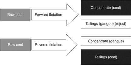
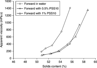
12.43 Effect of PSS10 dispersant on apparent viscosity (calculated at a shear rate of 100 s−1) of slurries prepared from the forward flotation concentrates. Source: After Ding and Laskowski, 2009). Copyright Taylor & Francis Group, LLC. (http://www.taylorandfrancis.com), reproduced with permission.
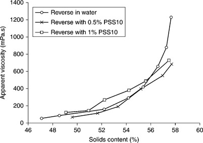
12.44 Effect of PSS10 dispersant on apparent viscosity (calculated at a shear rate of 100 s− 1) of slurries prepared from the reverse flotation tailings. Source: After Ding and Laskowski, 2009). Copyright Taylor & Francis Group, LLC.(http://www.taylorandfrancis.com), reproduced with permission.
The first and the most obvious difference is that in the first case, that is when the froth product from forward flotation is used to prepare CWS, the dispersant is needed to increase the CWS loading (Fig. 12.43). PSS10 dispersant (polystyrene sulfonate with MW of 14 000) was from LION Corp., Japan. In the latter case, when the flotation tailings from the reverse flotation are used, high solids loading can be obtained without any dispersant (Fig. 12.44). This product is sufficiently hydrophilic and does not require the dispersant to prepare CWS. The reverse flotation is not as simple as forward flotation and in the case discussed required the use of cationic collector (Arquad 12–50 from AKZO Nobel) along with some depressants/ dispersants (dextrin, tannic acid and A-100 polyacrylamide flocculant from Cytec). This, however, does not look so bad if compared with the dosages of dispersing additives that must be used in the preparation of CWS (they are usually in the range of 1%, that is 10 kg/t) when flotation froth product is utilized.
12.5.3 Rheology of magnetite dense media
Dense medium separation
In a dense-medium separation raw coal is introduced into the dense medium, whose density is higher than the density of the lighter constituent (coal) but lower than the density of the heavy constituent (inorganic rock). In a perfect separator, the particles have an infinite time to report to either sink or float products. In practice, a limited time is available for the separation, and the rate with which the particles move (relative to the medium) determines the outcome of the process. Particles characterized by a small density differential or small size do not move in the medium fast enough and will be misplaced. Thus, the separation efficiency is based on the phenomena that determine sedimentation of solid particles in liquids.
Settling phenomena
A particle settling in a liquid under gravity is subject to two forces, a driving force due to gravity and a drag force that opposes motion. The equation resulting from such considerations that describes the terminal velocity of solid particle in a liquid can be written in the following form:
where d is the spherical particle diameter, δ is the particle density, ρ is the liquid density, and Cp is the dimensionless drag coefficient.
the drag acting upon the moving particle depends also on the medium viscosity (η) but to the extent that depends on the prevailing hydrodynamic conditions.
For small spherical particles (d < 100 μm)

and this, when substituted into Equation [12.15], gives the Stokes equation
As this equation indicates, the settling rate of small particles strongly depends on medium viscosity.
For large particles (d > 1 mm) Cd ≈ 0.44 and Equation [12.15] gives Newton’s equation
showing that in a turbulent flow regime the settling rate of spherical particles does not depend on viscosity at all.
There are a few empirical equations (e.g. Allen’s equation) that were derived for the intermediate Reynolds number range 1 < Re < 103 (Concha and Almendra, 1979). They all indicate only weak dependence of the particle settling rate on viscosity.
The point is that the settling rate of solid particles in liquid strongly depends not only on particle size but also on the density differential (δ-ρ). For small values of this differential, that is for so-called near-density particles, the settling rate will be slow (as in the Stokes equation) also for larger particles. The movement of these particles in the medium will then also be described by the Stokes equation, and will strongly depend on the medium viscosity.
In a static dense-medium separation (dense-medium bath), the gravitational driving force responsible for sedimentation of solid particles in liquids is given by:
where g is the acceleration of gravity.
In a cyclone, the acceleration of gravity is substituted by a centrifugal acceleration (Sokaski et al., 1991)
where Fc is the centrifugal force, V is the tangential velocity, and r is the radius of cyclone.
In a typical cyclone, the centrifugal force acting on a particle in the inlet region is about 20 times greater than the gravitational force in a static bath, but in the conical section of a cyclone this force is much larger. These large forces responsible for separating coal from inorganic gangue are therefore much larger in a cyclone than in a static bath. This explains the cyclone’s large capacity and its ability to process fine coal particles.
Dense media
The most common media for separation is a fine magnetite suspension in water, ferrosilicon suspension, or a mixture of the two, depending on the required separation density. Magnetite alone is used when a density is required in the range from 1.25 to 2.2 g/cm3, a mixture between 2.2 and 2.9 g/ cm3, and ferrosilicon alone for a density range 2.9–3.4 g/cm3. With magnetite density of about 5.0 g/cm3, 500 g of magnetite per liter of suspension, that is magnetite content of 10% by volume (35 % wt.) the suspension density is 1.4 g/cm3, and with doubled magnetite content to 20% by volume (55% wt) magnetite suspension density will be 1.8 g/cm3.
The same calculations for ferrosilicon alloy, assuming that its density is 6.8 g/cm3 (Collins et al. (1974) claims that density of ferrosilicon containing 14–16% Si falls in the range from 6.6 to 7.0) give for the range of media densities from 2.9 to 3.4 g/cm3 the ferrosilicon volume percent of 33–41%.
According to Mikhail and Osborne (1990), the following is the standard particle-size distribution of magnetite used in coal preparation: maximum 5% by mass coarser than 45 μm, and 30% by mass finer than 10 μm.
Magnetite medium viscosity
Berghofer (1959) was probably the first to obtain full rheological curves for magnetite dense-medium suspensions. His results clearly demonstrate plastic properties of such suspensions (see Fig. 12.30) and show that the deviation of the rheological properties of magnetite suspensions from Newtonian behavior quickly increases with fineness of the magnetite. Meerman (1959), Whitmore (1958), and Yancey et al. (1958) sampled magnetite dense media from operating coal preparation plants and confirmed that such suspensions behave like Bingham plastic fluids.
A few samples of magnetite used in our rheological studies (He and Laskowski, 1995) are listed in Table 12.3.
Table 12.3
Particle-size distributions of the tested magnetites
| Sample | d63.2 (μm) | M |
| Mag #1 | 30.5 | 3.2 |
| Mag #2 | 18.0 | 1.6 |
| Mag #3 | 33.0 | 4.1 |
| Mag #4 | 4.3 | 1.9 |
| Mag #5 | 2.7 | 2.5 |
Particle-size distributions of the tested samples (Table 12.3) are well described by the Rosin-Rammler-Bennett (RRB) particle-size distribution: d63.2 is the size modulus (d63.2 is that aperture through which 63.2% of the sample would pass), and m is the distribution modulus (the slope of the curves on the RRB graph paper), with diminishing value of the distribution modulus the line representing distribution becomes less steep and that translates into larger differences between the sizes of fine and coarse particles in the sample.
Mag #1 was the Craigmont Mine commercial magnetite used in western Canadian coal preparation plants. Mag #2 was prepared by grinding Mag #1. Mag #3 was obtained by rejecting fines from Mag #1 in a classifying cyclone. Mag #4 and Mag #5 were micronized magnetites (70% and 90% below 5 μm, respectively), provided by the US Department of Energy in Pittsburgh (Klima et al., 1990).
Because of high magnetite density, in spite of fine size of the magnetite particles in the tested samples, these samples settle rather quickly and rheological measurements require special equipment. A sensor system (ESSP) that was specially designed and built for magnetite suspensions (Klein et al., 1995) was employed in the tests, along with a HAAKE Rotovisco RV 20 rheometer. The suspensions were demagnetized with the use of demagnetizing coil before measurements. The results are shown in Fig. 12.45 (He and Laskowski, 1999).
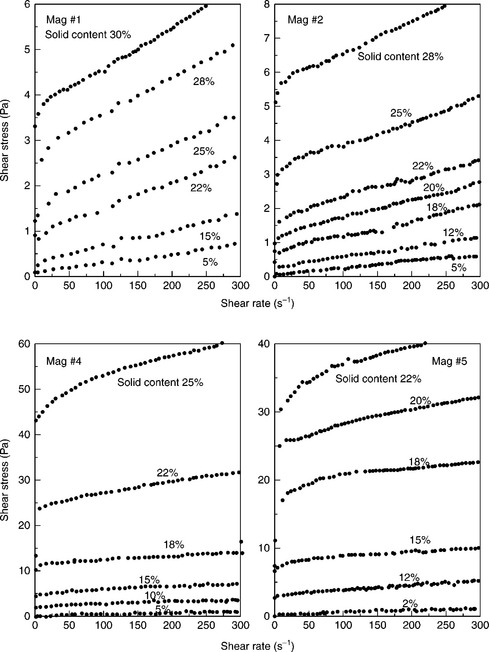
12.45 The flow curves of the tested samples of magnetite suspensions. Source: After He and Laskowski, 1999). Copyright Taylor & Francis Group, LLC.(http://www.taylorandfrancis.com), reproduced with permission.
As these results indicate, the yield stress for coarse magnetite suspensions (Mag #1) at solids content below 10% by volume is very low and the existence of yield stress is more clearly manifested in the fine magnetite suspensions (Mag #4 and Mag #5). High yield stress values in these suspensions provide a proof for quite strong particle-particles interactions in such fine disperse systems.
A few equations exist to describe rheological curves. Perhaps the most common is the Bingham equation, which describes the flow curves of plastic fluids (see Fig. 12.30).
where τ is the shear stress, τB is the Bingham extrapolated yield value (see Fig. 12.46), ηpl is the plastic viscosity, and D is the shear rate.
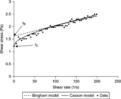
12.46 Example of rheogram of slurry fitted with either Bingham model or Casson model; as this example demonstrates, obtained τb and τc values are not identical.
The equation shown to describe rheological curves of magnetite suspensions particularly well is the Cason equation (Klein et al., 1990; He and Laskowski, 1999; He et al., 2001)
where τc is the Casson yield stress and ηc is the Casson viscosity.
Figure 12.47 shows the Casson yield stress determined from the experimental data displayed in Fig. 12.45.
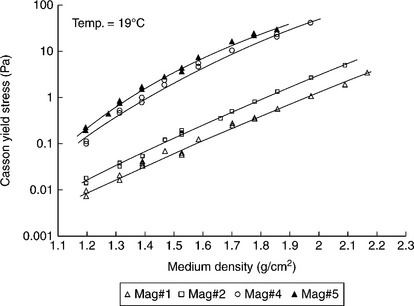
12.47 The effect of magnetite particle size and medium solid content on Casson yield stress. Source: After He and Laskowski, 1995). Copyright Taylor & Francis Group, LLC.(http://www.taylorandfrancis.com), reproduced with permission.
As Fig. 12.47 reveals, the Casson yield stress is very sensitive to the changes in the size of magnetite particles and solids content, while the Casson viscosity turned out not to be very sensitive to these changes over the studied medium density range (it is practically constant over the medium density range from 1.2 to 1.7 g/cm3). The Casson yield stress and viscosity values for four tested magnetite samples at a medium relative density of 1.45 are given in Table 12.4.
Table 12.4
Casson yield stress and viscosity for four studied magnetite samples at a medium relative density of 1.45
| Sample | τc (mPa) | ηc (mPa.s) |
| Mag #1 | 62 | 1.85 |
| Mag #2 | 118 | 1.50 |
| Mag #4 | 2110 | 0.70 |
| Mag #5 | 2660 | 1.50 |
As these results demonstrate, the yield stress values are much larger than the viscosity, and while the yield stress increases with the fineness of the tested magnetite samples, the Casson viscosity does not. Since the apparent viscosity of a non-Newtonian system (such as magnetite suspension) is determined by both yield stress and viscosity (that is either by Bingham yield stress and plastic viscosity, or Casson yield stress and Casson viscosity), it can be shown that the contribution coming from the yield stress exceeds by far the contribution of the viscosity (He et al., 2001).
Mineral particles that are treated in a dense medium must move in the medium in order to report to the proper products (low density concentrate or high density tailings). In order to start moving in the medium, in order to shear the medium (in a static bath this happens under gravity), the particles must overcome the threshold drag. It is determined by the yield stress. In the dense-medium cyclone, the acceleration is dominated by centrifugal acceleration; the results shown in Figs 12.48 and 12.49 were calculated assuming centrifugal acceleration of 40 m/s2.
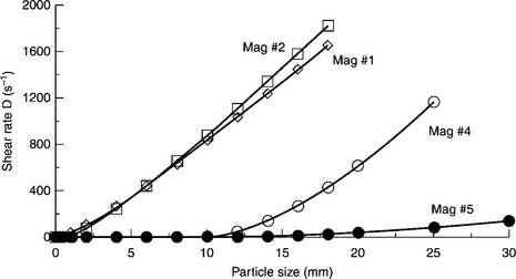
12.48 Effect of particle size on effective shear rate of a particles with a relative density of 1.55 in various magnetite dense media with a relative density of 1.45. Source: After He et al., 2001 with permission of Elsevier.
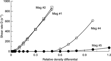
12.49 Effect of medium density differential on shear rate for a 2 mm particle in various magnetite dense media with relative density of 1.45. Source: After He et al., 2001 with permission of Elsevier.
As Fig. 12.48 shows, while only particles with size smaller than 1 mm will not be able to shear the Mag #1 and Mag #2 media (in a dense-medium cyclone at 40 m/s2 centrifugal acceleration), the near-density particles must be larger than 10 mm in order to be able to shear the Mag #4 medium.
For 2 mm particles, the movement in the Mag #1 and Mag #2 media requires only density differential larger than 0.1 g/cm3. In Mag #4 the particles with a size of 2 mm will be able to move in the medium only if their density is about 0.6 g/cm3 larger than the medium density (Fig. 12.49). These results demonstrate how important are dense-medium rheological properties for separation efficiency.
The medium capacity to maintain the homogeneity, the constant medium separation density δ50 in the separating device, is a function of medium stability. The medium used in dense-medium separation of coal is an aqueous suspension of fine magnetite particles. Static stability of magnetite suspension is defined as the reciprocal of the settling velocity that is easily determined in the lab (Bozzato et al., 1999). In a cyclone, magnetite particles are also subjected to centrifugal forces and tend to segregate creating density gradients. This tendency to segregate is a measure of the magnetite medium stability under dynamic conditions prevailing in a cyclone.
Practically, it is determined by the density differential between the cyclone underflow and overflow. As Fig. 12.50 indicates, the dynamic medium stability critically depends on magnetite particle size and medium density (that is magnetite concentration in the medium).
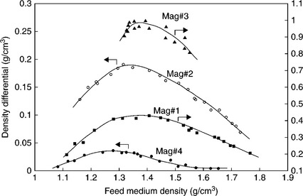
12.50 Effect of medium composition on medium differential measured in a 6” cyclone (D6B-12-S287 Krebs Engineering Int.) that was gravity fed at 10xD inlet pressure. Source: After He and Laskowski 1995). Copyright Taylor & Francis Group, LLC.(http://www.taylorandfrancis.com), reproduced with permission.
These measurements confirm that the measured density differential clearly depends on magnetite particle size, and it was shown to be a function of the yield stress (He and Laskowski, 1994). As could be expected, Mag #3 turned out to be very unstable, as characterized by a huge density differential of 1 g/cm3. For Mag #1 the maximum density differential is about 0.4 g/cm3. Collins et al. (1983) claim that separation efficiency is satisfactory as long as the medium density differential is in the range of 0.2–0.5 g/cm3.
All the studies confirm that the behavior of the medium is process-determining. In the empirical relationship proposed by Napier-Munn (1990) to describe the effect of medium rheology on DMC separation, the separation efficiency expressed by a value of Ep was related to the medium apparent viscosity by:
where Ep is the probable error, and Φ is a function of apparent viscosity, Φ = f (ηa, cyclone geometry).
Since the yield stress is a dominant factor that determines the apparent viscosity of fine magnetite suspensions, the experimentally measured yield stress can practically substitute for apparent viscosity in Equation [12.25] (He et al., 2001).
Optimizing medium composition is essential to achieving balanced stability and rheological properties of the dense medium (He and Laskowski, 1995). The effect of medium composition on DMC performance depends on feed particle size. The separation of coarse particles (larger than 2 mm) is strongly affected by the medium stability and only slightly by medium rheology. Thus, the separation efficiency improves when medium stability is improved by using finer magnetite dense medium. On the other hand, the separation of fine feed particles (below 0.5 mm) is more strongly affected by the medium rheology.
12.6 References
Agus, M., Carbini, P., Ciccu, R., Ghiani, M., Satta, F., Tilocca, C., The influence of coal properties on surface-based separation processes’Blaschke, W., eds. New Trends in Coal Preparation Technologies and Equipment – Proc. 12th Int. Coal Prep. Congress, 1996:571–578. [Gordon and Breach].
Aplan, F.F. Coal properties dictate coal flotation strategies. Mining Eng. 1993; 45:83–88.
Arnold, B.J., Aplan, F.F. The hydrophobicity of coal macerals. Fuel. 1989; 68:651–662.
Arnold, B.J. Efficient handleability of coal for power plants: development of a coal handleability index. Coal Preparation. 2004; 24:139–158.
Arnold, B.J. Coal handleability – addressing the concerns of the electric utility industry. January: Mining Engineering; 1992. [84–89].
Attar, A., Sulfur groups in coal and their determinationKarr, C., eds. Analytical Methods for Coal and Coal Products; 3. Academic Press, New York, 1979:585.
Attar, A., Dupuis, F., Data on the distribution of organic sulfur functional groups in coalsGorbaty, M.I., Ouchi, K., eds. Coal Structure; 192. Adv. Chemical Series, Am. Chem. Soc, Washington, DC, 1981:239–256.
Baker, M.D., Malicsi, A.S., Iwasaki, I. Effect of coal on the corrosive wear of grinding media. Minerals & Metallurgical Processing. 1990; 7:110–113. 414
Barnes, H.A., Hutton, J.F., Walters, K. An Introduction to Rheology. Amsterdam: Elsevier; 1989.
Berghöfer, W. Konsistenz und schwertrubeaufbereitung. Bergbau-wissenschaften, 6(20), 493–504;. 1959; 6(22):533–541.
Blaschke, Z., Influence of the carbon content, kind of gangue and of diesel oil on the results of coal beneficiation by oil agglomeration. Proc. 11th Int. Coal Preparation Congress, 1990:257–260. [Tokyo,].
Bloom, L.O., Edelhausen, L., van Krevelen, D.W. Chemical structure and properties of coal oxygen groups in coal and related products. Fuel. 1957; 36:135–148.
Brady, G.A., Gauger, A.W. Properties of coal surface. Industrial & Engineering Chemistry. 1940; 32:1599–1604.
Bozzato, P., Bevilacqua, P., Ferrara, G. Statics and dynamic stability in dense medium separation process. Mineral Processing and Extractive Metallurgy Review. 1999; 20:197–214.
Brown, D.W., Atkin, B.P. A method for rapid on-site assessment of handleability. Coal Preparation. 2000; 21:299–314.
Brown, D.W., Miles, N.J. Assessment of coal handleability. Coal Preparation. 2004; 24:99–122.
Botsaris, G.D., Glazman, Y.M., Stability and rheology of coal slurriesBotsaris, G.D., Glazman, Y.M., eds. Interfacial Phenomena in Coal Technology. Marcel Dekker, New York, 1989:199–278.
Brown, D.W. The effect of make-up procedure on the efficiency of flocculant solutions. Coal Preparation. 1987; 4:51–78.
Brown, P.M., Scheiner, B.J. ‘Dewatering of coal-clay waste slurries from preparation plants’, US Bureau of Mines Res. Invest.. 8836, 1983.
Brown, D.W., Factors affecting the handleability of coal and its measurement’. Coal International, 1997:147–149. [July].
Capes, C.E., Oil agglomeration process principles and commercial application for fine coal cleaning’Leonard, J.W., Hardinge, B.C., eds. Coal Preparation. Littleton, SME, 1991:1020–1041.
Capes, C.E., Germain, R.J., Selective oil agglomeration in fine coal beneficiationLiu, Y.A., eds. Physical Cleaning of Coal. Marcel Dekker, New York, 1982:293–351.
Chander, M., Polat, H., Mohal, B. Flotation and wettability of a low-rank coal in presence of surfactants. Mineral and Metallurgical Processing. 1994; 11:55–63.
Coe, K.S., Clevenger, G.H. Method of determining the capacity of sime settling tanks. Transactions on AIME. 1916; 55:203–210.
Collins, B., Napie-Munn, T.J., Scarione, M. The production, properties, and selection of ferrosilicone powders for heavy-medium separation. Journal of the South African Institute of Mining and Metallurgy. 1974; 75:103–119. [December].
Concha, F., Almendra, E.R. Settling velocity of particulate systems. 1. Settling velocities of individual spherical particles. International Journal of Mineral Processing. 1979; 5:349–367.
Concha, F., Rulyov, N.N., Laskowski, J.S. Settling velocities of particulate systems 18: Solid flux density determination by ultra-flocculation. International Journal of Mineral Processing. 2012; 104–105:53–57.
Cutress, J., Sproson, J.C., Runcie, J.M., Designs and Trials of Coal Handleability Machines. Internal Report, National Coal Board, Durham and Northern Divisions, Scientific Department. 1960.
Ding, K., Laskowski, J.S. Coal Reverse flotation. Part II: Cleaning of a sub- bituminous coal. Minerals Engineering. 2006; 19:79–86.
Ding, K., Laskowski, J.S. Effect of flotation on preparation of coal-water slurries. International Journal of Coal Preparation & Utilization. 2009; 29:84–98.
Ding, K.J., Laskowski, J.S. Effect of conditioning on selective flocculation with polyacrylamide in the coal reverse flotation. Transactions on IMM. 2007; 116:108–114.
Drzymala, J., Markuszewski, R., Wheelock, T.D. Influence of air on oil agglomeration on carbonaceous solids in aqueous suspensions. International Journal of Mineral Processing. 1986; 18:277–286.
Drzymala, J., Wheelock, T.D. ‘Air-promoted oil agglomeration of moderately hydrophobic coals, Part II. Coal Preparation. 1997; 18:37–52.
Elyashevich, M.G. Contact angles as a criterion of coal floatability. Trans Donetsk Industrial Institute, Gosgortiekhizdat. 1941; 32:225–235. [(In Russian)].
Farris, R.J. Prediction of the viscosity of multimodal suspensions from uni- modal viscosity data. Transactions of the Society of Rheology. 1968; 12:281–301.
Farrow, J.B., Swift, J.D. A new procedure for assessing the performance of flocculants. International Journal of Mineral Processing. 1996; 46:263–275.
Ferrini, F., Battarra, V., Donati, E., Piccinini, C., Optimization of particle grading for high concentration coal slurry. 9th Int. Conf. Hydraulic Transport of Solids in Pipes, 1984. [Rome, Paper B2.].
Flory, P.J. Principles of Polymer Chemistry. Ithaca, NY: Cornell University Press; 1953.
Fowkes, F.M. Attractive forces at solid liquid interfaces. Industrial & Engineering Chemistry. 1964; 56(12):40–52.
Frangiskos, N.Z., Harris, C.C., Jowett, A. The adsorption of frothing agents on coals. Proc. 3rd Int. Congress Surface Active Substances, Kohln. 1960; 4:404–415.
Fuerstenau, D.W., Rosenbaum, J.M., Laskowski, J.S. Effect of surface functional groups on the flotation of coal. Colloids and Surfaces. 1983; 8:153–173.
Fuerstenau, D.W., Pradip. Adsorption of frothers at coal/water interfaces. Colloids and Surfaces. 1982; 4:229–243.
Good, R.J., Badgujar, M.K., Huang, T.L.H., Handur-Kulkarni, S.N. Hydrophilic colloids and the elimination of inorganic sulfur from coal: a study employing contact angle measurements. Colloid and Surface A. 1994; 93:39–48.
Gregory, J. Particles in Water, London. London: Taylor & Francis; 2006.
Gregory, J., Nelson, D.W., A new method for flocculation monitoringGregory J., ed. Solid–liquid Separation, Chichester, Ellis Hordwood, 1984:172–182.
Gutierrez-Rodriquez, J.A., Purcell, R.J., Aplan, F.F. Estimating the hydro-phobicity of coal. Colloids and Surfaces. 1984; 12:1–18.
Hall, D.A., Cutress, J.O. The effect of fines content, moisture and added oil on the handling of small coal. Journal of the Institute of Fuel. 1960; 33:63–72.
Hara, S., Arai, H., Sugawara, H., Ukigai, T., Yoshida, E., Ogawa, J., ‘Development of additives for concentrated coal-water mixture, Proc. 17th Int. Conf. Coal Utilization and Slurry Technologies, Clearwater, U.S. Dep. Energy, 1992:71–82.
He, Y.B., Laskowski, J.S. Contact angle measurements on discs compressed from fine coal. Coal Preparation. 1992; 10:19–31.
He, Y.B., Laskowski, J.S. Effect of dense medium properties on the separation performance of a dense medium cyclone. Minerals Engineering. 1994; 7:209–221.
He, Y.B., Laskowski, J.S. Dense medium cyclone separation of fine particles. Parts 1 and 2. Coal Preparation. 1995; 16(1–26):27–49.
He, Y.B., Laskowski, J.S. Rheological properties of magnetite suspensions. Mineral Processing and Extractive Metallurgy Review. 1999; 20:167–182.
He, Y.B., Laskowski, J.S., Klein, B. Particle movement in non-Newtonian slurries: the effect of yield stress on dense medium separation. Chemical Engineering Science. 2001; 56:2991–2998.
Henderson, J.M., Wheatley, A.D. Factors affecting the efficient flocculation of tailings by polycrylamides. Coal Preparation. 1987; 4:1–50.
Higashitani, K., Umemoto, T., Kashiwabara, Y., Ito, H., Mechanism of viscosity reduction in highly loaded coal water slurry. Proc. 11th Int. Coal Preparation Congress, Tokyo, 1990:323–326.
Hogg, R., Polymer adsorption and flocculationLaskowski, J.S., eds. Polymers in Mineral Processing – 3rd UBC-McGill Int. Symposium. CIM Metallurgical Society, Quebec City, 1999:3–17.
Hogg, R. Polymer adsorption and flocculation. In: Laskowski J.S., ed. Polymers in Mineral Processing – Proc. 3rd UBC-McGill Symp. Montreal: CIM Met Soc; 1999:3–18.
Hogg, R., Brunnaul, P., Suharyono, H. Chemical and physical variables in polymer-induced flocculation. Mineral and Metallurgical Processing. 1993; 10:81–85.
Hogg, R. Dewatering of fine coal. In: Kawatra S.K., ed. High Efficiency Coal Preparation: An International Symposium. SME: Littleton; 1995:409–418.
Holland, A.B., Apostolides, G.A. Particulate material processing. Chem. Process. Eng.. 1969; 49:63–66.
Holuszko, M., Laskowski, J.S., Coal heterogeneity and its effect on coal floatability as derived from flotation tests in methanol solutionsLaskowski, J.S., Poling, G.W., eds. Processing of Hydrophobic Minerals and Fine Coal – Proc. 1st UBC-McGill Int. Symp. CIM Metal. Society, Montreal, 1995:145–164.
Holuszko, M.E., Laskowski, J.S., The effect of wettability on coal bulk density and its handleabilityOnal, G., Acarkan, N., Celik, M.S., Arslan, F., Atesok, G., Guney, A., Sirkeci, A.A., Yuce, A.E., Perek, K.T., eds. Proc. 23rd Int. Mineral Processing Congress, Istanbul; 2, 2006:1156–1165.
Holuszko, M.E., Laskowski, J.S. Use of pelletization to assess the effect of particle-particle interactions on coal handleability. Coal Preparation. 2004; 24:179–194.
Holuszko, M.E., Laskowski, J.S., The effect of wettability of coal on its bulk densityHonaker, R.Q., eds. Proc. 16th Int. Coal Preparation Congress. Lexington, SME, 2010:912–921.
Honaker, R.Q., Luttrell, G.H., Yoon, R.H., Upgrading of carbonaceous materials using selective hydrophobic coagulation’Laskowski, J.S., eds. Particle size enlargement in mineral processing – Proc. 5th UBC-McGill Symp. CIM Met Soc, Montral, 2004:89–104.
Honaker, R.O., Patwardhan, A. In-plant evaluation of dense medium process performance. Coal Preparation. 2006; 26:149–164.
Horsley, R.M., Smith, H.G. Principles of coal flotation. Fuel. 1951; 30:54–62.
Jiang, C., Wang, X.W., Leonard, J.W., Parekh, B.K., On the native and induced floatability of coal and pyriteParekh, B.K., Groppo, J.G., eds. Processing and utilization of high sulphur coals V. Elsevier, Amsterdam, 1993:171–188.
Johnson, S.B., Franks, G.V., Scales, P.J., Boger, D.V., Healy, T.W. Surface chemistry – rheology relationships in concentrated mineral suspensions. International Journal of Mineral Processing. 2000; 58:267–304.
Jones, G.S., Some solutions to the problem of handling wet coal fines. Proc. 11th Int. Coal Prep. Congress, Tokyo, 1990:7–12.
Kapur, P.C., Fuerstenau, D.W. Size distribution and kinetic relationship in the nuclei region of wet pelletization. Industrial & Engineering Chemistry: Process Design and Development.. 1989; 5:5–15.
Keller, D.V. The contact angle of water on coal. Colloids and Surfaces. 1987; 22:21–31.
Keller, D.V. The separation of mineral matter from Pittsburgh coal by wet milling. Chemistry of Mineral Matter and Ash, Amer. Chem. Soc. Div. Fuel Chemistry. 1984; 29(4):326–336.
Keys, R.O., Hogg, R. Mixing problems in polymer flocculation. AIChe Symposium Series. 1979; 76(190):63–72.
Kitchener, J.A., Flocculation in mineral processingIves, K.J., eds. The Scientific Basis of Flocculation, 1978:283–328. [Alphen aan den Rijn, Sijthoff & Noordhoff].
Klassen, V.I., Coal Flotation. Gosgortiekhizdat. 2nd Ed, 1963. [Moscow. (In Russian).].
Klein, J., Conrad, K.D. Characterization of poly(acrylamide) in solution. Macromolecular Chemistry. 1980; 181:227–240.
Klein, B., Laskowski, J.S., Mular, A.L. Rheology on magnetite dense media: modelling and control. In: Proc. 11th Int. Coal Preparation Congress, Tokyo. Japan: Mining and Materials Processing Inst; 1990:51–56.
Klein, B., Laskowski, J.S., Partridge, S.J. A new viscometer for rheological measurements on settling suspensions. Journal of Rheology. 1995; 39:827–840.
Klima, M.S., Killmeyer, R.P., Hucko, R.E., Development of a micronized magnetite cycloning process. Proc. 11th Int. Coal Preparation Congress, Tokyo. Mining and Materials Processing Inst, Japan, 1990:145–149.
Koral, J., Ullman, R., Eirich, F.R. The adsorption of polyvinyl acetate. Journal of Physical Chemistry. 1958; 62:541–550.
Krieger, I.M., Dougherty, T.J. A mechanism for non-Newtonian flow in suspensions of rigid spheres. Transactions on Society of Rheology. 1959; 111:137–152.
Krieger, I.M. Rheology of monodisperse lattices. Advances in Colloid and Interface Science. 1972; 3:11–136.
Kulicke, W.M., Clasen, C. Viscosimetry of Polymers and Polyelectrolytes. Berlin, Heidelberg, New York: Springer-Verlag; 2004.
Labuschange, B.C.J., Influence of oil consumption, pH and temperature on the selective agglomeration of coal’. ICHEME-5th Int. Symp. Agglomeration, Brighton, 1987:505–514.
Laskowski, J.S. Coal surface chemistry and its role in fine coal beneficiation and utilization. Coal Preparation. 1994; 14:115–132.
Laskowski, J.S. Coal Flotation and Fine Coal Utilization. Amsterdam: Elsevier; 2001.
Laskowski, J.S., Parfitt, G.F. Electrokinetics of coal-water suspensions. In: Botsaris G.D., Glazman Y.M., eds. Interfacial Phenomena in Coal Technology. New York: Marcel Dekker; 1989:279–328.
Laskowski, J.S., Yu, Z. Fine coal particle aggregation in coal preparation plant circuits. In: Partridge A.C., Partridge I.R., eds. Proc. 13th Int. Coal Preparation Congeress, Brisbane, Australian Coal Prep. Society, 591–599. Brisbane: Australian Coal Prep. Society; 1998:591–599.
Laskowski, J.S., Yu, Z. Oil agglomeration and its effect on benefication and filtration of low-rank/oxidized coals. International Journal of Mineral Processing. 2000; 58:237–252.
Laskowski, J.S., Luttrell, G.H., Arnold, B.J. Coal flotation. In: Fuerstenau M.C., Jameson G., Yoon R.H., eds. Froth Flotation – A Century of Innovation. SME: Littleton; 2007:611–636.
Leonard, J.W., Newman, D.A. Volumetric efficiency and the potential for increased productivity in underground haulage: a discussion of plans and concepts. Mining Engineering. 1989; 41:1202–1205.
Leonard, J.W., Paradkar, A., Groppo, J.G., Handle more coal by increasing its bulk density, 1992:317–318. [Mining Engineering, April,].
Lockhart, N.C., Veal, C.J. Coal dewatering: Australian R&D Trends. Coal Preparation. 1996; 17:5–24.
Mayers, R.A. Coal Desulfurization. New York: Marcel Dekker; 1977.
Meerman, P.G., Interface-active chemicals in coal preparation. Proc. 2nd Symp. on Coal Preparation, Leeds, 1959:253–275.
Mehrotra, V.P., Sastry, K.V.S., Morey, B.W. Review of oil agglomeration technics for processing of fine coals. International Journal of Mineral Processing. 1983; 11:175–201.
Melik-Gaykazian, V.I., Plaksin, I.N., Voronchikhina, V.V. ‘On the mechanism governing the interaction of apolar collectors with certain surfactants during froth flotation'. Dokl. Akad Nauk SSSR. 1967; 173:883–887.
Melo, F., Pawlik, M., Laskowski, J.S., Effect of coal surface wettability on aggregation of fine coal particlesLaskowski, J.S., eds. Particle Size Enlargement in Mineral Processing – Proc. 5th UBC-McGill Int. Symposium. CIM Metal. Society, Hamilton, 2004:105–119.
Michael, A.S., Bolger, J.C. Settling rates and sediment volumes of flocculated kaolin suspensions. Industrial & Engineering Chemistry Fundamentals. 1962; 1:24–33.
Mikhail, M.W., Osborne, D.G. Magnetite heavy media: standards and testing procedures. Coal Preparation. 1990; 8:111–122.
Mikka, A., Smitham, J.B., Coal handleability assessment. C.N., Bensley. Third Australian Coal Preparation Conference. Australian Coal Preparation Society, Wollongong, 1985:12–27.
Milana, G., Vettar, A., Wheelock, T.D. Air-promoted oil agglomeration on moderately hydrophobic coals, Part I. Coal Preparation. 1997; 18:17–36.
Miller, K.J., Deurboruck, A.W., Froth flotation to desulfurize coal’Liu, Y.A., eds. Physical Cleaning of Coal. Marcel Dekker, New York, 1982:255–291.
Miller, J.D., Lin, C.L., Chang, S.S. MIBC adsorption at the coal/water interface. Colloids and Surfaces. 1983; 7:351–355.
Mishra, S.K., Dewatering of fine coal’Mishra, S.K., Klimpel, R.R., eds. Fine Coal Processing. Noyes Publications, Park Ridge, 1987:225–268.
Napier-Munn, T.J. The effect of dense medium viscosity on separation efficiency. Coal Preparation. 1990; 8:145–166.
Nicol, S.K., Rayner, J.G. Oil-assisted filtration of fine coal. International Journal of Mineral Processing. 1980; 7:129–135.
Ohki, A., Xie, X.-F., Makajima, T., Itahara, T., Meda, S. Change in properties and combustion characteristics of an Indonesian low-rank coal due to hydrothermal treatment. Coal Preparation. 1999; 21:23–34.
Olson, T.J., Aplan, F.F., The floatability of locked particles in a coal flotation systemPark, W.C., eds. Proc. 2nd Int. Conf. Applied Mineralogy in Minerals Industry. Metallurg. Soc. of AIME, Warrendale, 1984:367–393.
Owen, A.T., Nguyen, T.V., Fawell, P.D. The effect of flocculant solution transport and addition conditions on feedwell performance in gravity thickeners. International Journal of Mineral Processing. 2009; 93:115–127.
Pawlak, W., Turak, A., Ignasiak, B., Selective agglomeration of low rank bituminous and subbituminous cretaceous coalsCapes, C.E., eds. Proc. 4th Int. Symp. on Agglomeration. Iron and Steel Soc. of AIME, Toronto, 1985:907–916.
Pawlik, M. Polymeric dispersants for coal-water slurries. Colloids and Surfaces A. 2005; 266:82–90.
Pawlik, M., Laskowski, J.S., Liu, H. Effect of humic acids and coal surface properties on rheology of coal-water slurries. Coal Preparation. 1997; 18:129–150.
Potas, T.A., Sears, R.E., Maas, D.J., Baker, G.G., Willson, W.G. Preparation of hydrothermally treated LRS/water fuel slurries. Chemical Engineering Communications. 1986; 44:133–151.
Richardson, J.F., Zaki, W.N. Sedimentation and fluidization: Part I. Transactions of the Institution of Chemical Engineers. 1954; 32:35–53.
Riva, W.J., Hudson, H.P., Landon, J.E., Walsh, J.H. Coal pelletizing studies for the vertical shaft carbonization process. CIM Bulletin. 1964; 57:52.
Rosenbaum, J.M., Fuerstenau, D.W. On the variation of contact angles with coal rank. International Journal of Mineral Processing. 1984; 12:313–316.
Rubio, J. The flocculation properties of poly (ethylene oxide). Colloids and Surfaces. 1981; 3:79–95.
Rulyov, N.N. Application of ultra-flocculation and turbulent micro-flotation to the removal of fine contaminants from water. Colloids and Surfaces A. 1999; 151:283–291.
Rulyov, N.N., Ultra-flocculation: Theory, experiment and applicationsLaskowski, J.S., eds. Particle Size Enlargement in Mineral Processing – Proc. 5th UBC-McGill Int. Symposium. CIM Metallurgical Society, Hamilton, 2004:197–214.
Rulyov, N.N., Dontsova, T.A., Ja, Korolyov V. Ultra-flocculation of diluted fine dispersed suspensions. Mineral Processing and Extractive Metallurgy Review. 2005; 26:203–217.
Rulyov, N.N., Korolyov, B.Y., Kovalchuk, N.M. Ultra-flocculation of quartz suspension: effect of shear rate, dispersity and solid concentration. Mineral Processing & Extractive Metallurgy Review. 2009; 118:175–181.
Rulyov, N.N., Laskowski, J.S., Concha, F. The use of ultra-flocculation in optimization of the experimental flocculation procedures. Physicochemical Problems of Mineral Processing. 2011; 47:1–16.
Sablik, J., Makula, K., Olszowka, J., Rabus, S. Srodek do flotowaniawegli, zwlaszczawegli o niskimstopniuzmetamorfizowania. Polish Patent. 1977; 104:569.
Sastry, K.V.S., Fuerstenau, D.W., Kinetic and process analysis of the agglomeration of particulate materials by green pelletizationSastry, K.V.S., eds. Agglometaion ‘77; 1. SME, Littleton, 1977:381–402.
Sastry, K.V.S., Mehrota, V.P. Pelletization of coal fines: state-of-the-art. 3rd Int. Symp. Partikel Technologie. 1981; 2:H36–H51.
Sastry, K.V.S., Fuerstenau, D.W., Pelletization of fine coal. EPRI CS-2198 Research Project 1030–1., 1982.
Scheiner, B.J., Wilemon, G.M., Applied flocculation efficiency: A comparison of polyethylene oxide and polyacrylamidesAttia, Y.A., eds. Flocculation in Biotechnology and Separation Systems. Elsevier, Amsterdam, 1987:175–186.
Scheiner, B.J. Screen dewatering of coal-clay waste from preparation plants. Coal Preparation. 1996; 17:39–46.
Scheiner, B.J., Wilemon, G.M., Applied flocculation efficiency: a comparison of polyethylene oxide and polyacrylamide’Attia, Y.A., eds. Flocculation in Biotechnology and Separation Systems. Elsevier, Amsterdam, 1987:175–185.
Schubert, H. Capillary forces – modelling and application in particulate technology. Aufbereitungs Technik. 1984; 1:39–48.
Schwartz, E., Physical properties of coal surfaces and their interaction with stabilizers. Proc. 7th Int. Symp. Col Slurry Fuels Prep. & Utilization. U.S. Dep. Energy, New Orleans, 1985:41–49.
Seki, M., Kiyama, K., Nishino, J., Effects of coal property and additive on the rheological characteristics of coal water mixtures’. Proc. 7th Int. Symp. Coal Slurry Fuels Preparation and Utilization. U.S. Dep. Energy, New Orleans, 1985:136–145.
Shaw, D.J. Introduction to Colloid and Surface Chemistry. London: Butterworths; 1970.
Skiles, K.D., Search for the next generation of coal flotation collectors. Proc. 20th Annual Int. Coal Prep. Conf, 2003:189–204. [Lexington].
Sokaski, M., Sands, P.F., McMorris, W.L., Wet fine particle concentration Section: Dense MediaLeonard, J.W., Hardinge, B.C., eds. Coal Preparation. Littleton, SME, 1991:376–413.
Sun, S.C., Tu, L.Y., Ackerman, E. Mineral flotation with ultrasonically emulsified collecting reagents. Mining Engineering. 1955; 7:656–661.
Tao, D., Groppo, J.G., Parekh, B.K. Effects of polymers and metal ions on vacuum filtration of fine coal. Coal Preparation. 1999; 20:207–226.
Usui, H., Tatsukawa, T., Saeki, T., Katagiri, K. Upgrading of low rank coal by a combined process of vacuum drying and tar coating. Coal Preparation. 1999; 21:71–82.
Vickers, F. The treatment of fine coal. Colliery Guardian. 1982; 230:359–366.
Walsh, D.E., Owen, H.C., Rao, P.D. A study of non-evaporative hot water drying of an Alaskan low-rank coal. Coal Preparation. 1993; 13:115–130.
Wawrzynkiewicz, W. Determination of the handleability of power coals and factors generating its variability. Coal Preparation. 2004; 24:123–137.
Wawrzynkiewicz, W. Factors influencing transportability of steam coals. Inzynieria Materialowa. 2003; 1(9):27–37.
Wen, W.W., Killmeyer, R.P., Utz, B.R., Hucko, R.E., Simultaneous fine coal dewatering and reconstitution via U.S. Department of Energy in situ cake hardening processBlaschke, W.S., eds. New Trends in Coal Preparation Technologies and Equipment – Proc. 12th Int. Coal Preparation Congress, 1994:107–114. [Gorodn and Breach,].
Wheeler, T.A., Coal floats by itself – doesn’t it?Mulukutla, P.S., eds. Reagents for Better Metallurgy. SME, Littleton, 1994:131–142.
Willson, W.G., Walsh, D., Irwin, W. Overview of low-rank coal (LRC) drying. Coal Preparation. 1997; 18:1–15.
Whitmore, L.R. Coal preparation: The separation efficiency of dense medium baths. Journal of the Institute of Fuel. 1958; 31:583–591.
Xu, Z., Yoon, R.H. The role of hydrophobic interactions in coagulation. Journal of Colloid and Interface Science. 1989; 132:532–541.
Xu, Z., Yoon, R.H. A study of hydrophobic coagulation. Journal of Colloid and Interface Science. 1990; 134:427–434.
Xu, Y., Cymerman, G., Flocculation of fine oil sand tailsLaskowski, J.S., eds. Polymers in mineral processing – Proc. 3rd UBC-McGill Symp. CIM Met Soc, Montreal, 1999:591–604.
Xu, D.D., Aplan, F.F. Quoted after F F Aplan (1993), ‘Coal properties dictate coal flotation strategies’. Mining Engineering. 1993; 45(1):83–88.
Yancey, H.F., Geer, M.R., Sokaski, M., Viscosity – its measurement and importance in dense medium coal cleaning of fine sizes of coal’. Proc. 3rd Int. Col Preparation Congress, Liege, 1958:583–591.
Yoon, R.H., Basilio, C.I. Chemical–mechanical dewatering process. U.S. Patent. 1997; 5:670,056.
Yoon, R.H., Asmatulu, R., Yildrim, I., Eryadin, M.K., Luttrell, G.H. Pilotscale testing of novel fine-particle dewatering aids. Minerals & Metallurgy Processing. 2003; 20:206–210.
Yoon, R.H., Eryadin, M.K., Zhang, J., Keles, S., Luttrell, G.H., Development of advanced fine coal dewatering technologies. Proc. 15th Int. Coal Preparation Congress, Beijing, 2006:575–583.
Yoshihara, H. ‘Graft copolymers as dispersants for CWM. Coal Preparation. 1999; 21:93–104.
Zitterbart, M.T., Nichols, D.G., Lovenhaupt, D.E., Pyrite and ash liberation from selected coalsAttia, Y.A., eds. Processing and Utilization of High Sulphur Coal. Elsevier, Amsterdam, 1985:247–266.
Zhang Rong-Zeng, Fang, Zeng, Kun-Mu, Hu, Min-Qiu, Gao, Research on CWM preparation technique with Chinese coals. Proc. 6th Int. Symp. Col Slurry Combustion and Technology, Orlando, 1984:234–239.
Zuna Wang, Zhan, Rongzeng, Jiang, Zhiwei, Jiang, Shizin, Preparation of coal-water fuels from coal preparation plant fines. J.J., Davis. Proc. 6th Australian Coal Preparation Conference. Australian Coal Preparation Society, Mackay, 1993:418–427.