
Treatment of coal tailings
Abstract:
This chapter describes the treatment of fine coal tailings from a coal preparation facility, starting from the acceptance of tailings, or fine raw coal, into a plant thickener, which concentrates the tailings as a slurry, and produces clarified water for recirculation to the process plant. The methods of disposal of the thickened slurry tailings are discussed, from the types of filtration technologies available, to new methods, including deep cone paste thickening. All these dewatering processes are designed to recirculate the maximum amount of water to the plant and offer alternatives for the tailings solids disposal to the older solution of pumping to tailings pond, or dam.
16.1 Introduction
The global coal preparation industry is facing significant new challenges on two fronts: waste disposal and water consumption. Existing operations are coming under increased scrutiny and more stringent environmental constraints. Permits for new mining operations in well-developed mining areas have restrictions not previously imposed. Simultaneously, coal deposits in areas with limited water reserves, for example arid regions, or where the climate has long periods of sub-zero temperature, are being developed to meet increased global demand for a critical commodity for growth in the twenty-first century, and it is impossible to operate conventional water recovery circuits in such locations. It is clear that an industry that produces over 7 billion tonnes per year (2010) of saleable coal, and can consume some 200 litres of water per tonne of coal produced, has to manage water use carefully. The treatment of slurry tailings and water clarification from coal preparation plants is therefore a subject of increasing importance in the development of new mines and maintaining the operation of existing plants.
Slurry tailings are usually the product of a de-sliming process in the coal preparation plant, where material below a size between 1 and 0.1 mm is separated. This sizing process is achieved using large quantities of circulating water, sometimes up to 10 m3/h of water for every tonne of fine raw coal to be removed, prior to the main gravity-based coal preparation processes. Raw coal minus 1.0 mm or 0.5 mm in size is usually upgraded by froth flotation, or a combination of flotation and gravity concentration, before dewatering and being added to the products of the coarser coal separation. The tailings slurry arrives at the plant thickener as a dilute mixture of between 5% and 10% solids w/w. It is then mixed with a polyelectrolyte flocculent to assist settlement, thereby reducing the required thickener diameter, and improving the clarity of the overflow (clarified water), which is recirculated to the plant for use as a de-sliming medium, rinsing water, tank level control, and for general use. Thickener underflow can vary in concentration, depending on the type of thickening technology used. The key design consideration in the design of a slurry tailings system is the disposal of the thickener underflow. By far the simplest system is the pumping of the underflow to a tailings lagoon. This is possible if sufficient instantaneous fresh make-up water is available to replace the water which is pumped out in the thickened slurry.
There are several reasons why this simple method may not be feasible as a plant design. These are:
1. The plant is in an arid location and water losses in the tailings facility – by seepage or evaporation – cannot be made up from the available fresh water supply.
2. Return water from the tailings facility is required as part of the plant water balance and the plant is in a location of extreme cold temperature, where liquid effluents from the plant would freeze.
3. There is insufficient room to locate a tailings pond or dam that can hold the necessary capacity of tailings over the life of the mine.
4. The environmental permits for the mine do not allow a pond or dam, e.g. when the mine is located in, or near, a built-up or residential area.
5. The location of the mine is a place where stability of the discard tip and pond would be dangerous.
If any of the above criteria prevail, then it will be necessary to close the water circuit within the plant to maintain continuous operation. In this case several methods are available for dewatering of tailings slurry for disposal with the coarser discard from a plant, and recirculation of the recovered water to balance the plant water circuit. In certain situations, depending on the choice of dewatering technology for the tailings and the moisture content received with the raw coal to the plant, a water treatment system may also be required to treat the excess water before this is returned to a natural water course. In all cases, clarified water, which is the thickener overflow, is recirculated to the plant. The overflow is collected in a sump and pumped to a distribution head tank for use throughout the coal preparation plant.
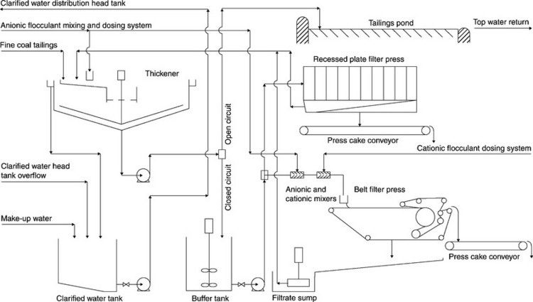
We will now describe each individual unit process in the treatment of coal preparation tailings. To do this we will follow the basic flow-sheet (Fig. 16.1).
16.2 Thickening
The settlement of fine particulate solids by sedimentation processes to reduce moisture prior to subsequent treatment.
16.2.1 Sedimentation theory
The three forces that control the way particles settle in a fluid medium are gravity, buoyancy and friction. The factors influencing these forces are:
For a common design characteristic (such as throughput), variations in any of the above parameters can have a major impact on the behaviour of the particles and must be taken into account in the design of the thickener. While the thickener designer can take certain elements into consideration from a fundamental understanding, there is a point where theory becomes incomplete and empirical testing must begin. The accurate sizing of a thickener or clarifier is a combination of applied theory and testing.
The relative settling characteristics of particles that can be separated into three basic regimes are shown in Table 16.1.
Table 16.1
Relative settling characteristics of particles
| Free independent particle settling systems | Settling rates are independent of particle concentration |
| Hindered settling | Settling rate steadily decreases as the particle concentration increases |
| Compression | Particles settling rate is restricted by the mechanical support of particles below, causing compaction and deformation |
Most thickeners operate with all three regimes present – certainly in any high rate thickener where feed dilution is used. One of the regimes will be the ‘rate determining step’ and this, together with the requirements of the process performance, will be the factor that determines the size and design of the equipment.
16.2.2 Synthetic polymers as flocculants and the development of high rate thickening
After arrival at the plant, the tailings slurry is mixed with a polyelectrolyte flocculent. The polyelectrolyte consists of long chain molecules which, when suitably hydrated or aged for a predetermined time, open up to present multiple negative, (anionic), or positive, (cationic) charges, to the fine tailings particles. The tailings particles with positive charge are attracted to the polyelectrolyte molecules and attach themselves. The laden polyelectrolyte forms ‘floccules’, which simulates the nature of a larger particle and therefore settles more readily and accelerates sedimentation. When flocculants are used as filtration aids, the formed floccules assist the filtration process similarly. The design of the flocculants is tailored for each specific application. They will be of various molecular weights and charge intensity according to the duty.
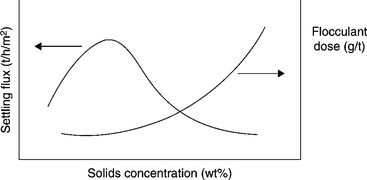
With the development of synthetic polymers as flocculants for the mining industry, a new design parameter – feed-solids concentration – came to have significant effect on the sizing and design of thickeners. This led to the development of a new type of thickener – the high rate or high capacity thickener. These terms now generally refer to thickeners which incorporate feed dilution into their design. Thickener throughput is directly dependent on flocculent dose and feed-solids concentration. The size of the thickener is generally governed by capital expenditure and the primary operating costs of flocculant. A smaller thickener may be less expensive to install but will incur higher running costs from the increased flocculant dose required to achieve throughput, underflow density and overflow clarity.
Feed dilution
Synthetic flocculants have an optimum feed-solids concentration for maximising settling flux – or thickener throughput – which is often lower than the solids concentration at which the process upstream of the thickener operates. In these circumstances, dilution of the feed stream will increase the settling rate and reduce the thickener area required for a given duty (Fig. 16.2).
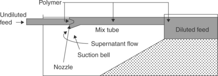
Many methods of feed dilution have been tried since the advent of synthetic flocculants. Modern feed-well designs incorporate recirculation of thickener supernatant into the feed-well to provide internal dilution using either the energy associated with the incoming feed, the difference in liquid level between the feed-well and the thickener water level, or a pumped recirculation of supernatant. Early dilution methods used slots or holes cut into the feed-well to draw dilution liquor into the feed slurry due to the density differential between the feed stream and the clarified liquor. The Outotec Flocmiser feed-well is an example of this type. An alternative method of dilution is to place an eductor or jet pump in the feed line to dilute, flocculate, and mix the slurry prior to its entering the feed-well. The degree of dilution can be designed in the eductor through the geometry of the eductor and the driving head of the feed slurry through the eductor. This type of feed-well is distinguished by the EIMCO E-Duc® Self-Diluting Feedwell. An example of this is shown in Fig. 16.3.
Thickener sizing
The thickener or clarifier area must be sufficient to allow the slowest settling particle to reach the bed of compressing solids or bottom of the tank before its associated liquid has reached the overflow. There is a critical concentration in the settling process that the solids will achieve for which the settling rate, and associated upward liquor flow rate, will limit the solids throughput rate. This normally occurs in the hindered or compression zones. The area requirements for thickeners are frequently based on the solids settling rates measured in the hindered or zone settling regimes, where the settling rate steadily decreases as the particle concentration increases. Since the surface area of the thickener is the main variable, the mass flow through the system is considered a flux (the product of concentration and velocity), such as tonnes solids/m2/day. Frequently the inverse of this flux is used, called ‘unit area’, m2/tonnes solids/ day. This allows system properties to be described in a general way for any size unit. The same nomenclature applies to clarifiers, where ‘rise rate’, the upward flow of supernatant to the overflow per thickener unit area, usually expressed as m3/min/m2 or m/min, limits or sets the criteria for overflow clarity.
16.2.3 Thickener rake design
It is possible, though not common, to have an unraked thickener, which will be covered in a separate section of this chapter. Here, however, we will deal with the three general types of thickener rake drive mechanisms;
Bridge mounted drives are supported on a bridge that spans the thickener, with the shaft and rakes suspended from the drive. (Because of the bridge, there is an upper limit on the size of machine this design can be economically applied to, generally around 40–50 m diameter.)
Centre column drives are used on larger thickeners. The drive is mounted on a centre column that (typically) also supports an access bridge spanning one half of the tank. The rake is suspended from the drive by a cage assembly that surrounds the centre column. The shorter bridge compensates for the addition of the column and the use of a cage around the column to drive the rakes. Column types are economical, starting at about 40 m diameter, and are currently available up to a diameter of 130 m.
Traction thickeners use a peripheral drive mounted on one (or two) of the rake arms. These units can develop very high torque, but do not have lift capabilities and are sensitive to environmental conditions regarding contact between the drive wheel and the rail or traction surface. They are usually considered only for very large diameter applications.
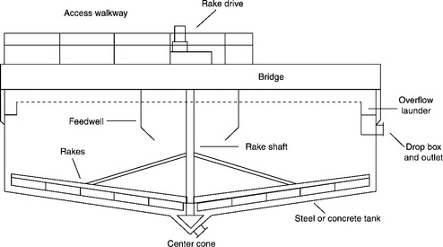
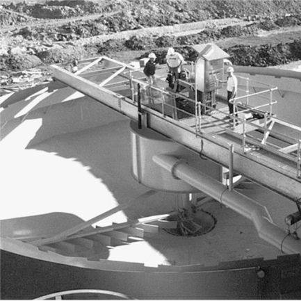
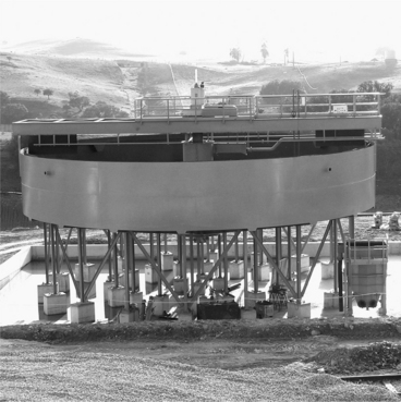
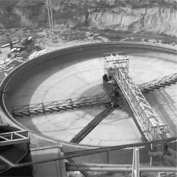
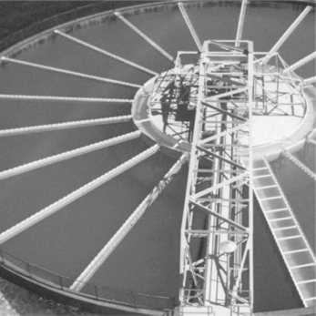
Conventional thickener design uses centre underflow outlets with the floor sloped at 1:12–2:12 towards the centre. Lighter duty applications such as clarifiers usually use a 1:12 slope. Large diameter machines often use a dual-slope design, with an inner slope of 2:12 and an outer slope of ½:12 or 1:12, to avoid making the machine excessively deep in the centre and incurring a high capital cost for the tank construction. Applications such as magnetite thickeners use steeper slopes, such as 3:12, to aid the movement of the high relative density thickened bed. The tank sidewall depth is usually about 3 m and is determined by both process and mechanical considerations. A freeboard of 150–300 mm is usually used on both the tank and feed-well. The centre outlet is typically a 45° cone on bridge type thickeners and a trench on centre column thickeners. Either requires a scraper assembly attached to the rake structure to keep the material moving. A generalised thickener is shown in Fig. 16.4. Figures 16.5 and 16.6 are photos of typical centre column and bridge mounted thickeners respectively.

Thickener drives
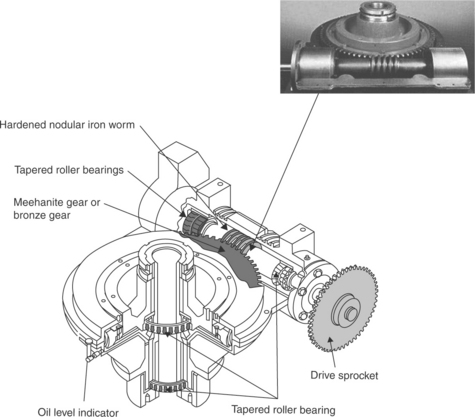
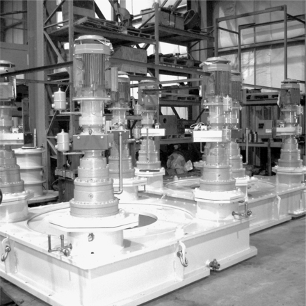
For many years thickener drive-heads were the proprietary design of the thickener manufacturer. Smaller diameter thickeners were powered by ‘worm-and-wheel’ type gear reducers mounted onto the drive shaft (Fig. 16.7). Larger units required multiple stages of reduction to develop the speed and torque required for the process application.
The introduction of epicyclic gear reducers allowed multiple individual stages of traditional primary gear reducers to be replaced by a single multistage gearbox, simplifying maintenance and reducing costs (Figs 16.8 and 16.9). Some smaller thickeners could be fitted with multistage boxes as the only gear reducer; however, the reduced lower bearing diameter has to be taken into consideration to ensure that bearing overturning moments from uneven rake loads do not cause risk of premature bearing failure.
Drive selection
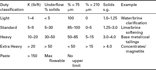
Thickener drives are selected to provide sufficient torque to maintain continuous operation under a wide range of conditions. The torque required for an application is calculated from empirical constant (K), which is proportional to the tank diameter:
Typical K factors for thickening applications are shown in Table 16.2.
16.2.4 Thickener tank configurations
The tank required to house the thickener mechanism can come in many forms, and its final selection will be influenced, amongst others, by:
A wide variety of thickener tank designs are currently being used. Most applications require that the underflow pump is located with as short a pump suction as practically possible, which means either that the tank has to be elevated or that there is a tunnel under the thickener to allow access to the centre of the thickener.
The costs and safety issues surrounding tunnels under thickeners normally arise in thickeners less than 35 m in diameter being elevated tanks – though there are elevated thickener tanks up to 65 m in diameter.
Common tank configurations are:
• Concrete floor and walls, either on-ground or elevated;
• Concrete floor and steel walls, either on-ground or elevated; and
• Steel floor and steel walls, either on-ground or elevated.
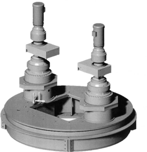
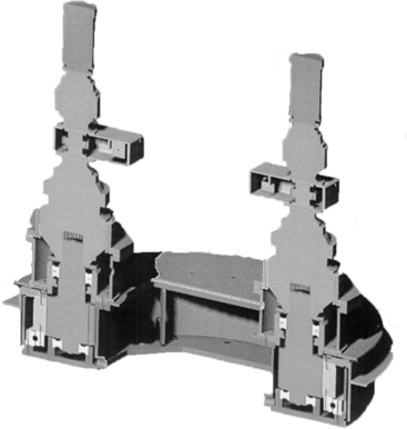
Recent developments in tank design have moved towards bolted tank assemblies, which are estimated to be 10–20% more expensive to fabricate but can save well over this amount in the cost of site erection. The principal savings in site work are the reduced use of mobile equipment and an erection team of skilled labourers rather than artisans. A thickener schematic is shown in Figs 16.11–16.13.

Rakeless thickeners
One of the few innovations in thickener design in the last 20 years has been the development of the rakeless thickener in South Africa by Wren Corporation. The Wren-CAT (now marketed as the E-Cat by FLSmidth) was developed as a combined clarifier and thickener with the object of producing a thick underflow and a very low solids concentration overflow simultaneously. The unit has several unique design features:
The central feed-well includes a circular tower of inclined plates which present a large settling surface area as the material settles through the feed- well. This additional surface area allows for significantly higher surface loading in an E-Cat as compared to a conventional or Hi-Rate Thickener.
Once the feed passes through the bottom of the feed-well, the supernatant is channelled through a series of clarifying cylinders, arranged in annular rings around the outside of the feed-well, where any remaining particles are combined into additional flocculated agglomerates, which settle into the base of the tank leaving a very low solids overflow to report to the peripheral launder.
The lower section of the tank has a 60°cone, which allows the underflow to flow to the discharge without the need for a rake to assist in the transport of the bed to the central outlet.
With a combination of a high throughput and therefore smaller diameter, the E-Cat is particularly suited to modular plant design (Fig. 16.14).

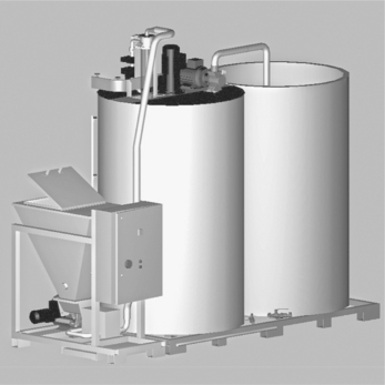
16.2.5 Flocculant preparation and dosing systems
Anionic polyelectrolyte flocculants, which are the most common type used to assist settlement of tailings solids and some types of tailings filtration, are generally prepared from powder. The powder must be dispersed and mixed with potable water. Several automatic flocculant mixing systems are available on the market. The systems usually mix the powder and liquid to an initial concentration of 0.1% solids w/w. After thorough mixing, the flocculent is transferred from the mixing tank to a stock tank prior to dosing. Different theories exist about storage, ageing and dosing, but generally the flocculant is mixed and stored at a concentration of 0.1% and dosed at this concentration through variable speed positive displacement pumps. The flocculant is diluted downstream of the dosing pump, in line, to 0.01% concentration. For a thickener application, the flocculant is added in the thickener feed launder and distributed across the full launder to achieve optimum mixing. If an internal dilution eductor system is employed, as described in Section 16.2, then the flocculant is added into the mouth of the dilution system to maximise mixing (Fig. 16.15).
16.2.6 Tailings ponds (open circuit)
If sufficient area is available close to the plant, by far the cheapest solution to tailings disposal is to pump the tailings from the thickener underflow to a pond or lagoon, where the solids can, over time, settle out to a dense saturated solid bed and the supernatant liquid can be recirculated to the plant as make-up water. In order to balance the circuit in the plant, sufficient clean make-up water needs to be available to instantaneously top up the clarified water and keep the plant water circuit in balance. The tailings pond/lagoon/ dam is a highly specialised civil engineering technology, and should always be professionally designed because of safety and environmental issues.
If all or part of the overflow from the pond is to be discharged into a water course (river, lake, sea), then the chemistry of the water must be carefully evaluated and a suitable water treatment solution chosen. See Section 16.11.
16.3 Tailings’ dewatering technologies
Historically, expenditure on tailings disposal has been minimal as there is no value in the product. The necessity to dewater tailings beyond the consistency of thickener underflow usually arises when environmental legislation, or lack of available space, dictates that the tailings must be discharged as a high solids waste. Occasionally, if insufficient instantaneous make-up water is available, or if operating in a sub-zero temperature climate, the tailings must be dewatered to close and balance the coal preparation plant water circuit. Dewatering of tailings is not a new design requirement in the coal industry. In Europe, it was common practice from the 1940s onwards to discharge the tailings as a solid waste. This is because many mines were located close to residential communities and the planning authorities would not allow discharge into lagoons for safety and environmental reasons. In addition, many mines were located in steep valleys, where the stability of the whole mine tip of larger discard and slurry was problematical. The process is becoming much more commonplace, though, due to environmental constraints and other reasons limiting the use of tailings ponds or lagoons.
Several technologies are used to dewater fine tailings from a coal preparation plant. The method of dewatering chosen is a function of the desired final solids concentration, the particle-size distribution, and characteristics of the fine particles in the slurry suspension arriving at the tailings thickener. Each dewatering device has unique features in terms of capacity and dewatering capability. Some devices produce very dry solids products and some less dry. Some require reagents to assist dewatering, and some do not. The principal technologies used are as follows.
16.3.1 Vacuum filters
Vacuum filters can be used for dewatering fine tailings, but the particle- size distribution in the feed should contain no more than 50% less than 75 microns in size – and generally no more than 50% ash, in order to be able to achieve a reasonable filtration rate and cake moisture. Vacuum filters are more commonly used to dewater fine clean coal, or fine raw coal if there is no fine coal processing in the plant. Several types of vacuum filters are used in these applications. Initially, rotary disc filters were used to maximise the filtration area, in a minimum footprint, but in later years belt discharge drum filters and horizontal belt vacuum filters have been used. The drum and horizontal belt types produce filter cake at a lower percentage free moisture content than the disc type, as the filter medium is continuously cleaned by means of high pressure sprays, and discharge is unaided. In the disc filter a ‘snap blow’ discharge system is usually employed to remove the cake, but can also discharge a lower solid content, higher moisture product.
In all cases the filtration is effected by creating a vacuum behind the filter medium using a liquid ring type vacuum pump. The filtrate is collected in the filter internal pipe-work, or through a grooved rubber belt and vacuum pan in the case of a horizontal belt filter.
In all cases filtrate is collected in a filtrate receiver and discharged by a sealed pump, or barometric leg system, to the circulating water system or plant effluent stream.
Vacuum filtration is often enhanced by a ‘filter-aid’ flocculent, which is added to condition the feed and form floccules to improve filter bed permeability and hence reduce moisture content of the cake. This in turn will also improve cake discharge and transportation.
16.3.2 Recessed plate filter presses, (Fig 16.17)
Recessed plate filter presses have been used in the coal industry for many years as the principal method of dewatering of fine tailings, usually from the froth flotation process. The tailings solids in the slurry are often of a very fine particle size up 40% minus 20 microns, and often contain high quantities of clays.
The significant feature of filter press technology is that it is a batch process. Consequently, a buffer tank with at least 1.5 × a full press cycle volumetric capacity is required to allow the thickener underflow pump to remain in continuous operation.
The filter press itself usually consists of a number of horizontally supported recessed plates, which are usually covered by filter cloths and made from moulded polyurethane. The plates are closed together by hydraulic cylinders, and adjacent plates create a chamber in which the filter press cakes are formed. The filtration is effected by pumping the slurry into the filter press, which will initially start to fill. Gradually solids will collect in the recessed plate chambers and the clear filtrate will pass through the filter cloths and be collected in ports at the press plate corners. As the cake builds up in the chambers, it creates greater resistance to the pump, and volumetric flow decreases. The pump pressure must be able to overcome the resistance to the volume flow. Filter press feed pump pressure must be able to achieve between 700 and 1500 kPA, depending on the characteristics of the material being filtered.
At the end of the filtration cycle, when the cake is fully formed, the pump volumetric flow will be reduced to a minimum figure and the filtrate will be negligible. Once the filtration cycle is complete the feed pump is stopped and the press closing mechanism is released. The plates are then opened and the press cakes are removed.
Filter presses come in many degrees of sophistication, reflecting the fact that this technology has been used for over 150 years, in a variety of industrial applications, and over 60 years in dewatering fine coal tailings.
Filter press technology is now capable of being fully automatic, where the cycle is fully automated and the separation of the plates can be achieved by an automatic mechanism moving the plates one at a time, or even all at once. The time taken to open, empty and close the press, ready for the next cycle, is dead production time and the key factor in sizing a filter press plant. Cycle times to form solid press cakes, approximately 20–25% free moisture, vary according to particle size, concentration of the feed, and material characteristics. Optimum cycle times are usually calculated from laboratory filtration tests.
Filtration cycle times for fine coal tailings are usually in the order of 30–90 min. The open/discharge/close cycle time must then be added to the filtration time to calculate an overall cycle time. The filter press capacity will be:
To calculate the dry tonnes per hour of solids, the free moisture content must be subtracted from the cake tonnes per hour.
Filter press capacity is a function of the volumetric capacity of the recessed chambers and the cycle time. Filter presses with plates as large as 2.5 M × 2.5 M and consisting of up to 200 chambers have been used on the fine coal tailings application.
There are several technologies which can also be used to speed up the filtration cycle, and these, again, depend on the nature of the material. Firstly, inflatable membranes can be inserted between the polyurethane recessed plates and the filter cloths. At a predetermined time in the filtration cycle, the membrane can be inflated, usually with compressed air, to ‘squeeze’ the partially formed cake. This membrane assistance can often reduce filtration cycle time and cake moisture. The downside is a reduction in the chamber volume, and the need for a compressor.
Another system is used to blow compressed air into the cake to drive out moisture during the filtration cycle. As a partial measure the centre inlet ports of the chambers, which form a segmented pipe in a closed filter press, are often subjected to an air ‘core blow’ to remove the residual slurry from the feed pump, thereby reducing cake moisture (by up to 1% w/w), and assisting discharge.
The pump technology used for filtration in a filter press has advanced significantly in recent years, with the advent of improved, and highly reliable, high capacity and discharge pressure of centrifugal slurry pumps. Originally a ‘fast fill’ centrifugal pump would be used to quickly fill up the press chambers with slurry. As the cake forms and pressure is built up, a switch would be made to a positive displacement pump to complete the press pump cycle to the required pressure. The most widely used positive displacement pumps were ‘ram’ type. These pumps were difficult to maintain, requiring constant maintenance to remain in service. In the 1980s these began to be replaced by more reliable ‘piston diaphragm’ pumps, but they were very expensive. Finally in the 1990s high pressure centrifugal pumps replaced most of the previous systems, so that now there is no need for change-over and complicated circuitry to effect the cycle. Depending on the pressure required, one or two stages of centrifugal pumps in series are used.
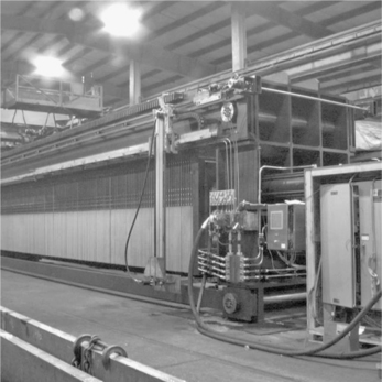
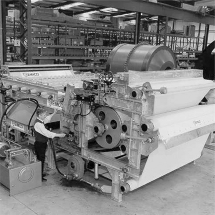
16.3.3 Continuous-belt filter press
The continuous-belt filter press has been used extensively in recent years as a lower capital cost means of dewatering fine coal tailings. It consists of a series of pulleys which squeeze moisture from the raw slurry. The raw feed is first conditioned in a feed tank and then pumped at low pressure to the filter. Flocculent is added to the feed via one or two static mixing vessels poisoned in the pump line. The raw feed is then fed to the press at atmospheric pressure, and the slurry forms quickly into a thickened, flocculated, state by settlement on the filter cloth. The very wet initial cake so formed is then captured between a second filter cloth and is subjected to squeezing through a series of pulleys, which remove filtrate and form the cake. The number of pulleys that the twin cloths enclosing the cake pass over, and the pressure applied will determine the level of dewatering achieved. Finally the cloths are separated and the finished cake is discharged from the end of the belt.
The benefits of these machines, compared to conventional filter presses, are that the process is continuous and the footprint in the plant required for dewatering is significantly less. The downside is that, for it to work efficiently, a large dose of polyelectrolyte is required and often two types of reagent are needed for best results (both anionic and cationic types). In addition, the moisture content of the filter cake will be much higher than that which can be achieved by a conventional filter press. It is more likely that the free moisture content of the cake will be in the 30% w/w top 40% w/w range. This makes the cake conveyable and most instances capable of being ‘co-disposed’ with the larger discard from the plant. In some instances, waste tip stability issues may mean that the cake from a belt filter press (Fig. 16.18) must be disposed of separately to a dedicated impoundment within the colliery tip. Capacities of approximately 8–10 tonnes per hour of cake can be produced per metre width of belt. Machines come in a range of belt dimensions, from 1.0 to 3.0 M wide.
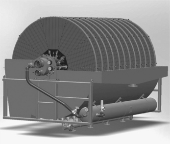
16.3.4 Solid-bowl centrifuge
Very high speed solid-bowl centrifuges are sometimes used as an alternative method to dewater fine tailings (Fig. 16.19). The solid-bowl machine has the advantage of being a continuous process and very compact for plant layout. It is also a very simple device to integrate into a plant layout. However, the product moisture is, as usual, a function of the particle size of the feed-solids, and the dosage of filter-aid flocculant added with the feed. The typical moistures achieved are similar to those of belt filter presses.

16.3.5 Comparative cost information
Generally speaking, the filtration techniques described above have very different capital and operating costs. The cheapest system is vacuum filtration but, as mentioned, this can be applied only in rare circumstances where the particle size is coarse and allows efficient dewatering by a vacuum filter. For most types of tailings dewatering, i.e. plate-and-frame filter presses, continuous-belt filter presses, and solid-bowl centrifuges, the capital costs of a plate-and-frame filter press plant are approximately double that of either a continuous-belt filter press plant, or solid-bowl centrifuge. However, if operating costs are considered, the plate-and-frame type has a significant advantage, as no polyelectrolyte ‘filter-aid’ flocculant is required, and significantly lower cake moistures can be achieved. In summary, if the issue is tip stability, or other such environmental issues, then the plate-and-frame filter press is generally the preferred choice. If it is purely for closing the water circuit, (e.g. very cold climates), the belt filter press has traditionally been the method used.
16.4 Water recirculation, discharge and process control
The handling of the recirculated Clarified Water from the Sedimentation process and it’s use in the Coal Preparation plant.
16.4.1 Clarified water circulation
The overflow from the tailings thickener in a coal preparation plant is defined as clarified water. Using the appropriate thickener design and suitable polyelectrolyte flocculants as described in this chapter, the clarified water should contain no more than 100 p.p.m. of suspended solids. The clarified water is collected in a sump, which should have a volume of at least 5 min of pumping capacity between a line one metre above the pump suction and the overflow level.
In an open circuit, i.e. where the thickener underflow is pumped to a pond or a lagoon, the volume of thickened slurry removed must be replaced by a suitable clean, make-up water source to balance the whole plant water circuit. In a closed-tailings liquid circuit plant, where the thickener underflow is dewatered by further means, only the balance of volume of free moisture on the plant products, minus the free moisture on the raw feed to the plant, must be replaced to balance the circuit. In some rare circumstances, the amount of free moisture leaving the plant with the dewatered products can be less than the moisture coming in to the plant with the raw feed. In these circumstances, in a closed-tailings liquid circuit, the clarified water sump can overflow. This means the excess water must be discharged into a river or some other water course, and must be treated prior to discharge. This water is also sometimes combined with excess water from the mining operations, prior to treatment. The level of treatment before discharge will always be subject to national legislation in the country where the plant is located.
The clarified water collected in the clarified water sump will be pumped for distribution in the plant, via a constant head tank located at a high level in the plant, to be able to access all points in the circuit, where it is required, by gravity flow. The clarified water pump should be designed with a capacity of the feed volume received at the thickener to allow for times when the thickener underflow pump has stopped. This excess flow will be returned to the clarified water sump, via the continuous overflow from the constant head tank, thereby ensuring that sufficient clarified water is available for the plant at all times.
Uses of clarified water in a coal preparation plant are as follows (but not limited to):
Non-magnetic sumps level controls;
De-sliming water make-up and sprays;
Clean water secondary sprays on dense medium drain and rinse vibrating screens;
Belt discharge vacuum filter cloth cleaning sprays;
Dilution water for dense medium specific gravity control; and
All the above water additions to the circuit will find their way eventually into the fine coal circuit and back to the clarified water circuit, via the tailings thickener.
If the tailings water circuit is closed, with further dewatering of the thickener underflow, the level of contaminants in the continuously recirculating water should be monitored. High levels of chlorine or other chemicals in the raw coal can be leached out of the coal, causing the water to become contaminated to the degree that certain types of pipe materials can be corroded. In addition, if the pH of the clarified water becomes too acidic, lime may be required to be added to modify the pH to an acceptable level for the flocculation process to work.
16.4.2 Water treatment prior to discharge
In order to meet discharge constraints, it is usual to treat process water, either overflow from the tailings thickener or supernatant decanted from the tailings dam, through a water treatment plant. The water treatment process will be dependent on the plant water chemistry and the discharge permit but will typically include pH adjustment, removal of dissolved metals, and removal of suspended solids.
These processes can normally be achieved with the addition of calcium ions – normally as lime – and the gentle recirculation and agitation of the resultant precipitate suspension.
This can be achieved in a series of stirred tanks, sized to provide sufficient residence time for the reaction to take place and followed by a clarifier to concentrate and remove the precipitated solids and provide a suitable overflow for discharge.
Alternatively, a combined unit where the dosing, conditioning, recirculation and settling are combined, such as a reactor–clarifier is used.
Reactor–clarifiers, as shown in Fig. 16.20 comprise a central conditioning cone inverted inside a raked clarifier. In order to mix the incoming feed, the central cone has a turbine, driven independently of the thickener rake that recirculates the conditioned feed with some of the settled solids in order to foster good precipitation and floccules growth.
The clarifier basin allows the solids to settle to the tank floor where they are raked to the centre for discharge, and the overflow is recovered through a series of radial launders, designed to lower launder approach velocity and minimise solids carry over to the effluent. Overflow solids concentrations as low as 20 ppm are commonly achieved.
16.4.3 Process control
Process control for tailings handling has developed along with the technology. In sedimentation, efficient clarometers can monitor the clarity of thickener overflow and utilise this to optimise polyelectrolyte consumption. Control techniques for batch filter press plants have also developed to monitor the cake formation process, and to automate the filtration and pump cycle. This has been used to optimise and minimise the filter press cycle time, thereby optimising capacity. Overall the tailings section of the plant is usually integrated into the plant DCS, although the batch filter press process is still often separately controlled.
16.5 Conclusion and future trends
Several developments are currently taking place in the equipment and processes used for fine tailings thickening and dewatering. Some of these will be implemented in the near future.
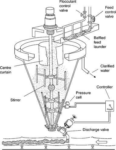
16.5.1 Deep cone thickening to produce ‘paste’
In the 1970s a new technique for thickening fine coal tailings was developed in the UK. This technique used deep cone thickeners (DCT) of approximately 4 m diameter with a 60° cone angle (Fig. 16.21). The small diameter units were installed in multiple groups to obtain the throughput required for each particular plant. The feed to the thickeners was heavily dosed with flocculant, and an extremely thick underflow density was achieved. The objective was to discharge the underflow from the DCT at a solids concentration to make it conveyable, and able to be co-disposed onto a solids waste tip with the other large discards from the plant. The underflow at a solids concentration of 60% w/w was then mixed with powdered cement and allowed to cure for 24 h. The cement stabilised mixture, which had a ‘biscuity’ texture, could then be co-disposed. Several systems were built and installed in the UK. The system had some drawbacks which prevented it from becoming widely used. These included high flocculant costs, the cost of the cement to stabilise the product, and the difficulty of controlling the thickening process due to the relative lack of residence time in the DCT units. Finally, the large-scale demise and eventual closure of most of the UK coal industry in the 1980s put paid to any further development.
In the 1990s paste thickening technology was further developed, initially by ALCAN, for disposal of the red mud effluent from the Bayer Process. This process, a refinement and development of the UK National Coal Board DCTs, produces an underflow product of ‘tooth paste’ consistency. The torque required for the process is much higher than a conventional thickener and, when taking the available bridge type thickener drives into consideration, limits the tank diameter. However, DCTs up to 40 M diameter are now in operation as the design has been further developed for very large throughput operations in the Andean copper mining operations, where water is at a premium and plant throughputs are very high. For the process of paste production to be viable, the size distribution of the feed must contain sufficient very fine particles to allow dense packing of these, within the interstices of the larger particles in the feed. The high compression head provided by the deep side walls, long residence time – as much as an order of magnitude higher than the bed residence time in a Hi-Rate Thickener – and special rake/picket design, combine to create the thick, paste-like underflow. Often a ‘shear thinning’ recirculation pump is required to assist the evacuation of the tank. Recirculating a portion of the thick underflow back through the specially designed discharge cylinder at the base of the tank breaks the bonds formed by the flocculant and lowers the apparent viscosity of the thick mud, making it easier to discharge from the tank.
In the alumina red mud application, the paste is pumped to a waste tip and distributed from a central point. The paste does not segregate into solid and liquid fractions, but consolidates into a solid consistency, which, in many cases, can support vehicles within 72 h. The saturated material placed on the tailings dam releases a little bleed water, but there will be no significant free water on the surface of the impoundment. This allows a different style of tailings facility to be constructed – one that does not have to retain water – at far lower cost. Significant savings can then be made in civil engineering costs for waste tip construction vs tailings dam construction. A well- designed thickened tailings facility – or paste tailings dam – will also allow closure and rehabilitation of the facility and a ‘walk away’ solution for the end of mine life.
The new DCT technology has now been used for treatment of tailings in almost all minerals applications including coal. The long residence time and comparatively low reagent requirements combine to make this a very low cost disposal method, with a high volume of the water being continuously circulated back to the plant. In coal applications the instability seen in the prototype units, installed in the UK in the 1970s can now be eliminated, and DCT is extremely simple to operate, and is virtually maintenance free.
Ultimately, the objective is to produce a conveyable DCT underflow, to allow co-disposal; alternatively, if very dry tailings are required for tip construction, the use of a DCT in place of a conventional thickener, prior to a dewatering filter press, has been demonstrated to significantly reduce the press cycle time, and hence increase the capacity of the filter press dewatering system.
16.5.2 Super polymers
Super-absorbent polymers (SAP) were first developed for use in hygiene products for Children. The concept of utilising these polymers was investigated for dewatering fine clean coal generated by preparation processes such as flotation. SAPs are granular highly cross-linked synthetic copolymers with excellent water-absorbing properties.
The dewatering process has three main stages:
1. contact of super-absorbent polymer with high-moisture fine coal;
2. separation of dewatered fine coal from super-absorbent polymer; and
3. regeneration of used super-absorbent polymer, by exploiting its response to changes in conditions such as pH or temperature.
While the separation stage had several hurdles, these were overcome by encapsulating the polymer in sachets that could be added directly to the thickened clean coal slurry. Furthermore, it was shown that it was possible to regenerate the polymer (still within the sachets) through thermal drying.
However, at the time the research was carried out, thermally regenerating the SAP was no cheaper than simply drying the coal – although clearly a significantly lower fire risk, as the polymer could be regenerated at 70 ° C.
16.5.3 Future trends
There are many avenues which future research into dewatering of tailings can lead. This will depend on the absolute necessity for closing the water circuit. As mentioned, this requirement can be for environmental reasons (usually dictated by legislation), or practical reasons (make-up water shortage, etc.). Either way, as the treatment of tailings generates no revenue, but is a cost in the processing of coal, further developments will be dictated by future levels of legislation and development of coal mines in more arid regions, or frozen terrains. If sufficient incentives are in place, further development of sedimentation, filtration and centrifugal techniques will be made. At present, several research establishments are working on combinations of electrical and microwave assistance to both filtration and to dewatering, and consolidation of unstable tailings ponds to make these useable for development.
The final and ultimate solution to tailings treatment is the ‘Holy Grail’ of coal preparation – the introduction of ‘dry’ processes for the separation of coal from impurities. This has been the subject of extended research for many years, ranging from simple air-jigging devices (which were used in the 1930s before the advent of mechanised mining) to more sophisticated cyclonic and optical sorting techniques. So far, these technologies have not been sufficiently efficient to match wet processing, and so have not yet been translated to a commercial scale. If these techniques can be mastered at a commercial scale, this would surely see a revolution in coal processing technology, similar to the introduction of dense medium cyclone technology in the 1950s. Should dry processing evolve, there will be no need for sedimentation or tailings dewatering and handling, as all discard products could be co-disposed in a dry solid form.