
Coal conveying
Abstract:
This chapter mainly discusses the design and operation of conventional trough belt conveyors in mining applications. There are also references to some of the emerging alternatives to troughed belts. The chapter looks at some of the important considerations in the design of large conveyor systems. Finally, integrated crushing and handling systems that receive material from haul trucks and feed the conveyor systems are also reviewed.
19.1 Introduction to belt conveyor technology
This chapter deals with conveying systems commonly employed for bulk material transportation, and covers aspects of their design and some of the key operational features.
The chapter is not intended to be a comprehensive text on the design details of troughed belt conveyors, or a review of the alternative conveying technologies, but covers details that are important to large conveyor designs that are not commonly found in the standard texts. For more comprehensive details on the design of conveyors, the reader is directed to Conveyor Equipment Manufacturers Association (CEMA) (2005), DIN22101 (2000), published papers and design manuals produced by the equipment supply companies, and also to the specific mining company standards, specifications and detail drawings.
A troughed belt conveyor consists of a wide belt typically running on three idler rolls. The outer wing rollers are sloped upwards to form the trough shape. The troughed belt then travels over the idler sets to transport the load. A conventional troughed belt conveyor has the following components:
• Idlers. These are rollers with bearings that form a trough shape for the belting. The idler sets are typically spaced out between one and three metres.
• Belting. The belting, which carries the load, rests on the idler rollers. Figure 19.1 shows the typical arrangement of the idlers supporting the belt. The belt is pulled around in a loop with tension/power supplied by drive pulley(s).

• Drive. Figures 19.2 and 19.3 show the pulleys and drives used to move the belt.

• Pulleys. The conveyor belt forms a loop. The carry side transports the load and the return side allows continuous cycling of the belt. The pulleys allow the belt to change direction at the loading and discharge ends, as well as direction changes on the return side.
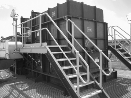
• Transfer chute. This is where the material is loaded onto or discharged from the belt. See Fig. 19.4.
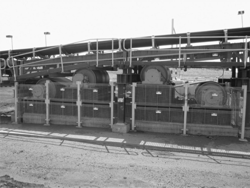
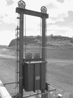
• Conveyor take-up system. The take-up applies tension to the belt to limit the sag between the idlers and prevent slip at the drive pulley. The take-up pulley moves to tension the belt. Take-up systems are typically gravity, but can be winch, screw or hydraulic jack. The typical arrangement has a pulley mounted on a trolley. The trolley is connected to a gravity mass in a tower via a cable. See Fig. 19.5.
19.1.1 Trends in conveyor design
Conventional troughed belts
The long-term trend for belt conveyors continues to be longer, faster, and higher capacity. The highest capacity conveyors include the 40 000 tph × 3200 mm wide belts on the Rheinbraun bucket-wheel excavators. The longest single flight conventional troughed conveyors include the 17 000 m long 1000 tph conveyor for transporting limestone that crosses the border between India and Bangladesh. More recently, an Australian company, Wesfarmers, commissioned a 20.3 kM 2500 tph × 1200 mm wide × 7.5 m/s coal conveyor at Curragh North Queensland mine. This was designed by Conveyor Dynamics Incorporated. The installed power is 4250 kW (4 × 1000 kW and 1 × 250 kW). There are 2 × 1000 kW tripper drives located at the mid position.
The use of the tripper drive concept is an extension of the underground mine intermediate drive arrangements that have been used for many years. These intermediate power injection designs have included piggyback booster belts, powered rollers, and tripper drives. Torsten (1982) described the mathematics of intermediate drive systems and how they could be used to minimise the tensions around horizontal curves. Weigel (1982) described a similar system used in a limestone mine. A more unusual idea, called the Ozomin drive, used the return belt to drive a section of the carry belt. This allowed the drive station to remain at the end of the conveyor. Some of the power from the drive would be shifted to a point along the carry belt, via the return belt.
The use of high speeds (for example, above 6 m/s), low energy rubbers and intermediate drives will allow longer and higher capacity conveyors. There are barriers emerging that will challenge this trend. These include noise, dust emissions, belt pressures on idler rolls, and lubricant loss. Conveyor systems, mines and populated areas are moving closer together, and environmental standards are changing and becoming more rigorous. There are direct relationships between belt speed, belt and idler roll surface geometry, noise, and dust levels. Technology may allow, say, a 9 m/s belt, but night-time noise restrictions at nearby homes may limit the speed to approximately half this value.
Non-conventional conveyors
In this context, non-conventional means non-troughed. An emerging technology in belt conveying is the Doppelmayr Ropecon system. This system has applications in rough terrain regions and environmentally sensitive zones. The conveyor can pass over these regions at a high level, as the conveyor is supported by cables between pylons like a suspended cable bridge. The span between the pylons can be up to 1500 m. The conveyor is a box-type flat belt with flexible vertical concertina side walls. The belt is supported by axles and wheels that travel on the suspended cables. That means the items that require maintenance, i.e. the wheels and bearings, travel around the system and back to a convenient point where the work can be safely done. The longest length to date is approx. 3500 m, and highest capacity approx. 3500 tph.
Other non-conventional conveyors include High Angle Conveyor (HAC), Cable Belt, Pipe-types, Rail conveyor, Aerial ropeways, Sicon and Aerobelt.
The HAC system uses an additional conveyor belt to create a sandwich. The upper belt applies pressure to hold the material in place as it moves up the steep incline.
Cable Belt conveyors use a cross-reinforced belt supported by cables on each side. The belt is almost flat, with a slight curve, so the supporting belt is separated from the tension member. (A conventional trough conveyor has the tension member within the belt.) The cables are supported by wheels spaced out several metres apart. The longest length is 31 kM + 20 kM and capacities around 4000 tph are located at a bauxite mine, Worsley Alumina Pty Ltd Western Australia.
Pipe conveyors are similar to a conventional trough conveyor, except the belt is wider so that it can wrap up into a circular or pipe shape. The idler rollers, say six in a hexagonal pattern, hold the belt in the pipe shape. Pipe conveyors can bend around smaller vertical and horizontal curves than conventional troughed belt conveyors. Pipe conveyors are good for dusty materials and conveying in and around process plants. The longest lengths are > 8 kM with capacities near 4000 tph.
The Rail conveyor is being developed at the University of Newcastle, Australia. The system has a troughed belt, support carriages with wheels that run on a railway track.
Aerial ropeways come in a couple of forms. There is the classic bucket hanging from a rope (like the chairs on a ski lift). The bucket would hold several cubic metres of material. Doppelmayr and others supply this type of machine for low volumes over difficult or complex routes. Aerobelt conveyors are like conventional troughed belt conveyors, except the belt is supported by a cushion of air instead of idlers. There is an air plenum in the shape of a trough with many holes to allow the air to leak out and form the cushion. The longest length is near 800 m, and the speeds range up to 7 m/s. The maximum capacity is near 400 tph.
The Sicon conveyor has the belt hanging like a teardrop-shaped pouch, with the tension cables on the edge. These conveyors are good for dusty materials and conveying in and around process plants. The highest capacity is around 1000 tph and longest length 2.5 km.
19.2 Belt selection
Belt selection is critical to the reliability of the conveyor system.
19.2.1 Strength for tension
The technology of belting has been improving over time. Premature failures, manufacturing, operating costs, and the need for stronger belts has forced the change. A change to self-extinguishing fire resistant belting in Germany in the 1970s led to a series of early splice failures. The University of Hannover developed a belt splice fatigue testing machine and ran a crash programme to investigate and solve the problem. Flebbe (1988) describes the machine first being used at the University in 1975. Contitech had a similar machine – see Alles (1982) for details of the machine and investigations of time strength behaviour of belting. The University machine has been in operation since 1975. The research at the University with the support of the local belting suppliers, such as Contitech and others, led to changes to the DIN standards (Deutsches Institut Fur Normung E.V. the German national standard).
The approach adopted by DIN and Hannover University has been to focus on the actual tensions across the belt width, and the fatigue strength of the belt carcass or splice, the ratio giving the safety factor. The common, but perhaps less preferred, approach is to compare the highest average across the belt tension with the non-fatigued carcass ultimate strength. This approach, although common, is not preferred because it masks the actual situation. The work by Flebbe (1988) at Hannover University highlights a problem with using the ultimate belt strength as a reference for belt safety factors. The reference discusses the test results of two belts ST6600 and ST7500 kN/m. At the time, companies were making claims as to which had made the strongest belt in the world. At first glance, the ST7500 belt would appear to have been the stronger. However, the testing at Hannover University established that the fatigue strengths were 50% and 38%, respectively. So the ST6600 had a strength of 3300 kN/m after fatigue and the ST7500 had a strength of 2850 kN/m. Pedro (2004) used Goodyear dynamic splice test machine when reviewing a new splice assembly technique for steel cord belts. Pedro tested a ST1250 kN/m belt and an ST4500 kN/m belt on the Goodyear test-rig.
Hager (2000) gives an overview of the approach taken by DIN 22101.
19.2.2 Belt strength for impact and chute design
Conveyor systems are being built to handle larger volumes and at some mines very coarse materials. This trend may be driven by:
• The move to the use of central processing hubs. The hubs may be old facilities that are no longer adjacent to the material being mined. So the conveyor systems replace long-haul trucking.
• A change in the types of materials and the associated crushing equipment.
• A better knowledge and more confidence in the design of transfers.
Looking back to the 1970s, some of the early transfers had simple, large open chute arrangements with low impact idler systems. The designs originated out of Germany, where the material was sticky lignite. The situation called for large open chutes that could handle some build-up, but still allow the huge lumps to pass. These lumps originated from the very large bucket-wheel excavators. The designs used suspended or garland idler sets. Colijn (1973) describes how five-roll suspended sets are used successfully in the open mine pits at Rheinbraun in Germany. He provides a graph of the impact force for various support arrangements. Precismeca (1998) has similar curves for the impact loads on various idler support systems. As the large lumps hit the belt, the suspended sets would change shape and reduce the impact force. These arrangements fell out of fashion, due to the maintenance of the links between the idler rolls, cost, and mass of the suspended assembly. The large assemblies required lifting equipment to allow replacement. Even then, the work was not easy.
In Australia, in the 1960s, the iron ore and bauxite mines applied the German designs, making changes to the chutes to accommodate the particular nature of the iron ore and bauxite. Iron ore, being abrasive and heavy, forced a move to rock-box design. This minimised the quantity of wear materials and lowered the impact on the belts. It was possible as the ore was dry and free flowing. At the bauxite mines the raw bauxite tended to be small, less abrasive, and sticky during the wetter months.
So the chutes for most materials were kept large and open. The large open simple chute designs worked well. When material is dumped crudely onto a belt, the belt tracking is not that bad.
As the flows increased and the knowledge of the designers improved, the designs slowly changed. The technology improvement had the support of the mining companies and organisations that included: University of Hannover Germany; University of Newcastle in NSW, Australia; Jenike and Johanson, at the University of Wollongong, NSW, Australia; publications by CEMA of the USA; the Mechanical Handling Engineers’ Association in the UK; and others. These organisations have developed tests for flow properties, behaviour, and wear, as well as the science of bin, hopper and chute design.
In the 1970s, soft flow chutes were being used to improve the flows through the transfers. These chutes were useful for granular non-sticky materials. The benefits were reduced dust, degradation, and impact. Bringing the flow up to the outgoing belt speed improved belt life. Coal companies in the Hunter Valley of NSW, Australia and other areas used these chutes with great success at this time. Colijn (1972) reviewed the equations that describe the velocity of the upper and lower impact curved chutes. These designs are known more recently as ‘hood and spoon’. Roberts (1981) looked at the behaviour of the flow along flat walls and around curved plates. These chute designs and the associated equations were used successfully on the 13.1 km overland coal conveyor for Pt Kaltim Prima Coal, Indonesia. This conveyor was designed in 1989 and began operation early 1991. James (1992) describes the use of chutes to accelerate the coal up to the outgoing conveyor belt speed. This conveyor has been through a series of upgrades since 1991. More recently, the chutes have been replaced by commercially available units from Tasman Warajay, Australia. These chutes consist of complex 3D shapes that control and direct the coal flow.
With the increasing use of soft flow chutes for large flows, the issues of material stickiness, liner wear, and belt tracking began to re-emerge.
In recent times, there has been a trend towards conveying larger, heavier lumps and below water table sticky materials. As the soft flow hood and spoon arrangements tend to block or wear, there is a need to revisit the chute designs. Sticky material demands simpler open chute designs. Open chutes tend to be higher impact, so the open design requires belting and loading points with good impact capability.
Böttcher (1978) published a paper on impact strengths as part of the development of the 100 kM overland system in the western Sahara. Manufacturers such as Contitech (see Alles (1988)) include the impact strengths of various belt constructions. It is surprising how often the impact strength is ignored by conveyor designers. The main focus has been on the designs for tension.
A simple review of the major mining company standard drawings will show that the typical transfer height is 5.5 m or more. With lumps weighing above 65 kg, the impact at the loading point can be high. James (2007) described the move to design soft impact loading points for primary crushed material. The method described is a departure from:
19.2.3 Rubber power
Low energy rubber has been used in motorbike and car racing tyres, etc. for many years. Without this technology, tyres overheat, lose grip, and fail. The application of low energy theory to conveyors goes back to the 1960s. Work by Schwarz, Oszter, Behrands, Quass, Spaans, Jonkers, Funke, Hintz, Hager, and many others investigated the topic to address the issue of the resistance components such as idler seal drag, material flexing, etc. For example, Oszter (1980) showed that approx. 70% of the resistance of a long conveyor was due to the imprint, i.e. the rolling resistance of the idler roll on the belt cover. Hintz (1993) published similar results showing the high contribution of the indentation resistance for a large range of belt cover materials. Lodewijks (1995) provides a summary of a dozen or so authors and their indentation loss equations. More recent work has been done by Wheeler (2003) using a rubber viscoelastic test machine, tests of rollers on a travelling belt loop, and finite element analysis of the contact zone. The thesis also looks at the other loss components, including idler seal drag, belt flexure, etc.
19.3 Design of large conveyor systems
The drive is a key component in the conveyor package.
19.3.1 Large drive systems
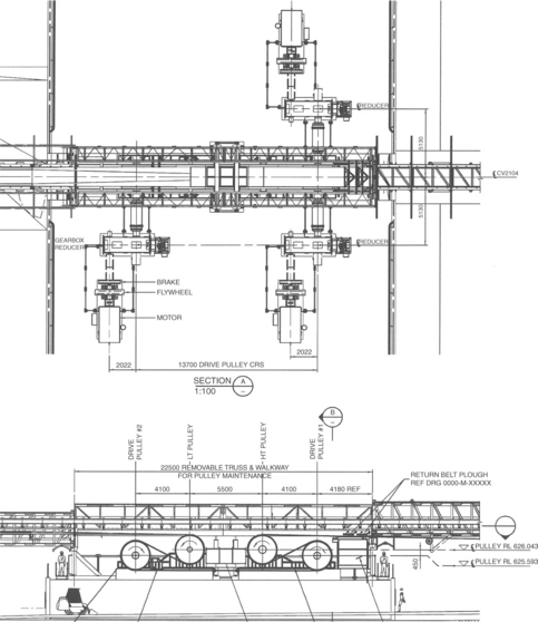
Please refer to Fig. 19.6. This shows a base-mounted drive assembly. This design was developed by James (2010) for the Worsley Alumina Pty Ltd Marradong Bauxite project and has been used more recently on the Rio Tinto Western Turner Syncline (WTS) project. The conveyor system on WTS has a total length of approx. 25 km. of which the longest flight is almost 11 kM long. There are 9 × 1600 kW drives, as shown in Fig. 19.6.
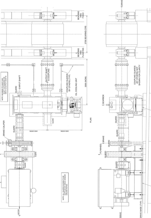
In some respects, the arrangement is a move back to the past. In the 1960s, base-mounted helical drives were used. These reducers used very large through-hardened gears. The housings were large, with large volumes of oil. These drives required good support structures to maintain the alignment of the couplings. As time passed and the required power became larger, the cost of the support structures, reducers and installation became prohibitive. These units were replaced by shaft-mounted bevel helical drives produced by Flender (now Siemens) of Germany and many others. These units used compact case-hardened gears. The small reducer and the shaft mounting arrangement created a low-cost solution that was quick to fit and did not require stiff support structures. As these drives increased in size, additional cooling systems were required. The old helical drives from the 1960s were very large for the power transmitted. Heat was less of an issue. However, the compact bevel helical case-hardened gear drives need fans, radiators, and water- or air-cooled exchangers.
The ever-increasing drive sizes have forced the move back in time to the arrangement shown in Fig. 19.6. The modern conveyors require drives that are measured in megawatts. The reducer alone may weigh 30 tonnes. The flywheel shown may weigh 7.5 tonnes with low-speed coupling of 3.5 tonnes. These are very large components. If this equipment was shaft-mounted, the entire assembly might weigh as much as 50 tonnes. The length might be several metres. The shaft-mounted drive would be difficult to lift, and access would become an issue.
The arrangement shown in Fig. 19.6 has extended couplings on both the high and low speed sides of the reducer. The longer couplings solve the alignment issue that forced designers to move to shaft-mounted drives. The couplings allow large alignment errors.
The holdbacks, backstops or anti-runback systems are devices that prevent a conveyor running backwards. The energy to cause the conveyor to run backwards may come from the conveyed load, the elastic strain energy, thermal transients, etc. The writer would use holdbacks on most conveyors even though the material lift load is less than the system friction. Thermal transients can be large. The method of calculating the loads is described in James (2007). This paper follows up on the work by Timtner (1996, 1998). Timtner discusses the wind-up multiplier effect within a holdback and through the drive system. He also looks at the effects of load sharing. It is common practice for holdbacks to be sized for the load from the lifted material. The work by James (2007) strongly advised that the stalled drive should also be considered. The stalled drive may produce 250% to 300% of the motor full load torque (MFLT). When this torque is multiplied by the wind-up effect, loads of 10 × MFLT are possible. This load is seen by the drives, pulleys, structure, etc. One way to limit these loads is to select holdbacks that slip momentarily when the extreme loads are generated.
19.3.2 Low head drive arrangements
Please refer to Fig. 19.7. This shows a low head drive arrangement. This design was developed by James (2010) for the Worsley Alumina Pty Ltd Marradong Bauxite project and has been used more recently on the Rio Tinto WTS project. Larger conveyors have larger powers and tensions. Larger conveyors have bigger pulleys. The conveyor tensions have moved past 100 tonnes, and the pulleys now weigh more than 25 tonnes each. The response to this trend is the low head arrangement. This arrangement brings the heavy pulleys and drives down to ground level. This provides improved access for maintenance. Smaller cranes can be used to lift the components. The arrangement shows access for a skid-loaded to clean up under the area. Light vehicles can drive up a concrete ramp and be parked beside the drives.
19.3.3 Horizontal curves
The design of horizontal curves has been covered by Grimmer (1972, 1992). More recently CEMA (2005) provided an update to the analysis of these curves. The preferred method of bending a conveyor around a curve is to use negative idler Camber and gravity. Some call this negative super-elevation. Here, the idler set is sloped so that it is higher on the inside of the horizontal curve. As the tensions rise, the belt moves towards the centre of the curve. In doing so, it moves up the idler slope. The extra gravity from the displaced belt resists the belt movement. If the design is correct, the belt will find a balance point with a reasonable belt drift. When the tension reduces, the belt moves outwards to another balance point. As the belt is moving sideways with variation in tension and load, consideration must be given to the material edge clearance and idler set width.
The published methods also consider friction as a method to control the belt movement. The friction is achieved by skewing and rotating the idler rolls or sets. This is less preferred because:
• The friction can vary with climatic conditions, rubber properties, and idler condition. There are many variables that make the prediction of the friction factor problematic.
• The extra friction drives up the tensions that flow back into belt movement.
• Higher tensions mean more power, and bigger drives and belt.
• There are many load cases that must be accommodated. Friction may help in some cases and be a problem for others. For example, friction may be beneficial for, say, the high tension empty belt case. It may limit the inward movement of the high tension empty belt (as it is being loaded). However, the friction works against stability for the loaded belt low tension case. For example, during a braked stop when the tensions go low, the loaded belt will be moved further out sideways due to this friction.
The accepted method to control the empty belt high tension case is by side guide rollers.
19.3.4 Conveyor starting systems
There are many systems available, including:
• Variable voltage variable frequency (VVVF).
• Wound rotor motors with step resistors, and liquid resistors.
• Fluid coupling, both static traction and scoop.
• Slipping clutch. For example, Baldor CST drives.
• Eddy current coupling. (These drives were used extensively at the lignite power stations in Victoria, Australia. Refer to Mitchell (1983).)
James (1992) describes the successful use of Voith scoop fluid on couplings on a 13.1 km overland coal conveyor located in Indonesia. The system was found to be simple and robust. More recent projects have used VVVF drives. Users such as Port Waratah Coal Services, Newcastle, NSW, Australia use a large number of wound rotor motors with liquid resistance starters. Some of the big miners in Australia use wound rotor motors with step resistors on larger drives. They will also use VVVF drives on specific conveyors.
The writer has not used slipping clutch systems. However, it is understood that slipping clutch systems, by Baldor for example, also have good end-user support.
19.3.5 Dynamics of starting and stopping
General
The dynamic behaviour occurs when the conveyor is running, starting or stopping.
Running dynamic behaviour, including belt flap and structural resonance, will not be discussed in detail. Belt flap occurs when the roll or belt passing frequency is in sync with the belt stringflap frequency. Normally, the consequences are not significant. An interesting phenomenon that has been observed is classic flap vibration on the carry side causing the material to migrate. The even material load moves, to become discrete masses equal to the idler frame pitch and causing considerable vibration and spillage. The vibration can be explained by string theory with distributed concentrated masses.
Starting dynamic behaviour is influenced by the drive start system. The starting cases can be smooth and carefully controlled by the drive system. The starting method can be by VVVF, fluid coupling, wound rotor motors, slipping clutches, etc. A flywheel, although not normally used for this purpose, can also extend the starting time and smooth out the dynamic behaviour.
Funke (1974) looked at the basic equations that describe the dynamic behaviour of conveyor belts. Nordell (1984) and Funke (1987) also address the issue. Lodewijks (2002) provides a historical overview of two decades of dynamic analysis work going back to Oehmen (1959) and Dumonteil (1967).
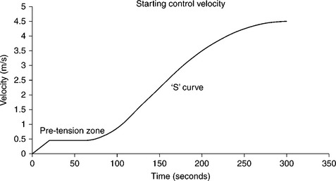
Harrison (1984) described the shape of the ‘S’ curve starting method. Refer to an example in Fig. 19.8. This curve minimises the dynamic response. In simple terms, there is no acceleration at the beginning or end of the start cycle, and maximum acceleration at the middle of the cycle. The starting cases are interesting but less challenging than the unplanned stopping cases. The normal planned stopping events can also have a controlled ramp down of the speed. The unplanned events, such as loss of supply power, or detection of, say, belt rip will cause immediate loss of power and a large step reduction in the tension applied by the drive system.
The stopping dynamics will be discussed in more detail below.
CEMA (2005, Chapter 16, p. 498) looks at the analysis of the transient system and asks the question: ‘When is Dynamic Analysis Required?’ It provides a basic check list. In short, the list includes existing conveyors that have problems, new conveyors greater than 1 mile (1609 m) long, conveyors with high lift or high regeneration, multiple drives, conveyors greater than 8000 tph or 1000 fpm (5.1 m/s), etc.
Stopping dynamics
James (2000) described a simple method to approximate transient dynamic tensions in belt conveyors when they are stopping. These tensions can be significantly higher than those predicted by conventional methods. High transient tensions are often the primary cause of equipment failure. The effect of these rules on various take-up systems is also discussed. The rules assume that the conveyors are a simple spring, and the tensions adjust at high speed. The rules are not a substitute for full dynamic analysis methods (i.e. actual forces may be higher than predicted by this method).
Conveyor analysis methods published by CEMA, DIN and ISO do not consider the dynamic response of the elastic conveyor during starts and stops. They are generally called static methods of analysis, where the belt is considered to be a rigid body. A number of practitioners, including the writer, have developed sophisticated dynamic programs that take into account the elastic behaviour of the belt and other dynamic properties. Although the theory has been in the public domain since the 1960s, the programs are not commonly available or used. The majority of conveyors are not designed using the dynamic analysis methods. The experts with the tools are often called in when there is a problem in the field, or when a designer considers the conveyor to be ‘big’. This is a dangerous approach. The potential for catastrophic failure is ever-present. Some try to cover dynamic loads with simple tension multipliers. This approach is not recommended. Ultimately, if there is a problem it may be expensive to solve. There may be overload due to high tensions or spillage from low tensions. Sag snap is when the belt quickly goes from low tension to high tension, or high to low sag. Under the right conditions, material can be thrown off the belt.
James (2000) discusses in simple terms the possible dynamic effects. The paper encourages designers to move from the simple static methods to full dynamic analysis using sophisticated dynamic tools. The reference describes a simple method that gives the approximate tensions during a stop. The paper noted that this method is not a substitute for full dynamic analysis methods. The paper includes a few simple rules, which are based on conservation of the average belt tension and its relationship with take- up travel. The rules will often give higher tensions at non-drive pulleys than predicted by the static methods. This depends on the actual conveyor arrangement. The rules may still under-predict the tensions. Although the average tension and take-up movement is conserved, the conveyor in the field may have a zone of low tension, which is compensated by a zone of high tension elsewhere.
Equipment
The key equipment required to control the stopping dynamics are brakes and flywheels. The loss of power during a non-planned stop sends tension waves around the conveyor. These waves travel approximately at the speed of sound. The conveyor tensions move from the running state to the stopped state. In simple terms, the conveyor is a spring mass system, and the loss of power is the step forcing function.
Flywheels add inertia to the drives. They convert the sharp step function into a longer ramp. It is interesting to note that the extra inertia generally has little effect on the full conveyor stopping time. However, the extra inertia has a large effect on the tensions around the conveyor and the associated take-up movement.
Recent examples of designs by the writer place the flywheel between two oil lubricated bearings FAG LOE or SKF SNOL housings. As an initial reference point, the diameter is limited by the rules specified by Factory Mutual Datasheet 13–6.
Brakes can serve a couple of functions. They can inject a value of tension say at the tail pulley to ‘hold up’ the tensions. Typically, the tensions near the tail of the conveyor may drop during a stop. Brakes can also be used at the drives to control the run-on time of the non-full belt cases. For example, with large flywheels, the empty belt may run on for more than 100 s. Proportional brake systems can be used to bring all load cases to a stop in a constant time.
Another tool that can be exploited is the take-up system. James (1994, 2000) describes the use of winch take-up systems. On stopping these systems lock in the tensions. The winch system cannot adjust quickly. So, as the tensions equalise at the speed of sound, they are seen by the pulleys. Provided the equipment can handle the loads, and effects such as ‘sag snap’ are not present, these take-up systems may be a viable solution. Note, some may consider the winch systems as adding complexity.
19.3.6 Discrete element modelling of chutes
The discrete element modelling DEM method is a computer simulation of discrete particles flowing through a chute. CEMA (2005, Chapter 16) provides a brief overview of the discrete element method. Wypych (2010) goes into the subject in more detail, noting that there is often a lack of validation of the model. A number software packages are available in the market, and companies are offering consulting services. As with any software, the output depends to a large extent on the quality of the inputs. There will also be a difference in the algorithms used and the complexity of the particle model, for example, the stickiness, elasticity and damping behaviour. So how valid are the inputs and outputs, and are the particles behaving correctly? Are the simulations fictitious animations, or is there a scientific basis?
Wypych has taken a scientific approach to the validation process, developing a series of tests and calibration techniques. With this in place the DEM outputs are compared with material flow physical scale chute models. The work shows close alignment between the methods. The work is ongoing.
19.3.7 Noise
Noise from conveying typically becomes an issue when the system is adjacent to local domestic residences. Noise limits at night are more restrictive than daytime limits. An example may be a port adjacent to a nearby town. Often the towns spread over time and the space between the old port and the homes gets smaller. Similarly the activity at the port and its function may increase over time. So over the years issues such as odour, dust and noise emerge. Also the community expectations and environmental standards change as the data of the environmental effects become known. This knowledge flows into the design of new and old facilities.
Brown (2004) discusses the deficiencies in understanding of the issue in some parts of the industry. This lack of knowledge can mean that once a noise issue is identified, there may be a limited number of practical and cost-effective noise management strategies that can be applied. A key input to the noise level is the belt velocity. Noise is generated at the belt/idler interface primarily by the idler surface profile velocity. A better understanding of the noise source would prompt the designer to consider lower belt speeds, larger idler roll diameters and/or better quality idler rolls.
Brown (2004) proposes a parameter called the Maximum Instantaneous Slope (MIS) that can be used as a practical basis to predict the noise levels from the equipment.
Various low noise idlers are available for the suppliers. These include:
• Machined and electronically balanced steel rollers. The machining improves the MIS value.
• Aluminium rollers with polyurethane ends. The aluminium tubing can have better MIS values than the un-machined steel tubing.
The reader is encouraged to investigate issues such as actual noise performance, shell wear, roll life, bearing life, grease retention, seal design, rolling drag, carry back adhesion, cost, availability, mass for replacement, standardisation, fire rating, corrosion resistance, etc.
19.4 Integrated crushing systems
Integrated systems move the truck dump point closer to the coal face by using conveyors.
19.4.1 General
With the shortage of truck tyres, and the cost and availability of labour, trucks and fuel, integrated crushing systems are becoming more popular. In a world where there are penalties for production of CO2, the move to integrated crushing systems is probably inevitable. Integrated systems have been used sporadically with great success for a number of decades, e.g. the design of the in-pit crushing plant for Bougainville Copper in the 1980s (not erected). At that time, companies such as Mountain States Engineers, Krupp, MAN, and others had built crawler transportable or walking type crushing and or conveying structures. Krupp had a range of out-of-the-catalogue crawler transporters, ranging from 240 t to 1200 t with a centred load. PHB-Weserhütte supplied mobile crushing units to Worsley Alumina Pty Ltd, Western Australia in 1981, and a number of other locations.
James (2010) gave details of a recent project where the ROM hopper for the haul trucks was moved. This is a fixed installation. The project study originally planned to have the ROM approximately 1000 m outside the pit. During the detailed design phase, the ROM was moved into the pit area. This reduced the annual truck travel by 250 000 km. This is about six times around the world. So, getting the ROM near the mining activity has major energy and cost benefits.
Chasing the mining activity with mobile or moveable semi-mobile modular systems is even better. Strzodka (1993) investigated the economics of in-pit crushing systems, and discussed the use of semi-mobile crushing systems. The work concluded that there were savings between 30% and 60% in favour of the in-pit crushing system. The example was of a 15 mtpa mine in Mexico.
Roberts (1985) looked at the components that make up the capital and operating costs of conveyors and other transport systems. The cost parameters would have changed, but the methodology is still relevant today. Constructing a series of graphs for operating and capital costs for various capacities and distances allows the methods and designs to be compared. For a conveyor, the optimum solution is normally narrow and fast.
19.4.2 Mobile and semi-mobile systems
The movement of large digging, crushing and conveying machines was not new to German and American designers. The Germans have been building large digging and transporting systems since the 1800 s. The power station in the Latrobe Valley, Victoria, Australia, used bucket-wheel excavator and track-shiftable conveyor technology to move overburden and lignite. The Heritage Victoria National Trust Database notes that LubeckerMaschinenbauGesellschaft (LMG), Lubeck, Germany, supplied the first dredger to Morwell open-cut. It began operation in 1955. The machine weighed 750 tonnes. The design of this machine originated in the German coal mines in the 1930s. The first German bucket chain excavators were used at Yallourn in 1928.
Haddock (2002) notes that a French contractor, Alphonse Couvreux, used a bucket chain excavator in 1859 on the Ardennes railway. In the period 1863–1868, seven Couvreux machines excavated 8 million yards of earth in the construction of the Suez Canal.
Haddock (2002) also notes that the American engineers were good at moving huge machines on crawlers. This reference describes stripping shovels as the ‘kings of the mobile machine world’. The early machines dating back to 1899 were mounted on rails. The book includes the details of many outstanding machines built in the twentieth century. One of the most impressive was the Marion 6360 stripping shovel, built in 1965. Mounted on an eight crawler undercarriage, the machine had a 180 cubic yard bucket. It weighed in at 15 000 t and had an operating radius of 220 ft.
In summary, the world’s engineers have moved huge items of equipment and there is now a real need to just do it!
It is interesting to ponder the question of why the systems have not been used more widely. One would speculate that in open pit mines the mine planners are reluctant to give up the flexibility of trucks. Conveyor systems quarantine parts of the pit, require extra planning, and reduce flexibility.
As we move forward, economic and environmental issues will challenge this view.
Considering the history of moving large equipment, moving ROM hoppers, jaw and gyratory crushers, sizers, apron feeders, electrical rooms, etc. is not a problem.
Kahrger (1987) described a new mobile conveying system to link in-pit crushers to the process plant. Track-shiftable and crawler-mounted bridge systems are also available. Caterpillar manufactures ‘out of the brochure’ crawler assemblies. Placing the typical conveyor truss/bridge on crawlers is not difficult.
Pagels (2008) describes the mobile crawler-mounted conveyors, stackers and reclaimers that have been used in heap leach operations for many years. Neagle (1983) described the moveable face conveyors used at the Loy Yang power station located in Latrobe Valley, Victoria Australia. Mitchell (1983) provided a 20-year history and a detailed tabulation of the 150–2440 kw drive-heads used at Morwell, Yallourn and Loy Yang lignite power stations Latrobe Valley, Victoria, Australia. The belt widths ranged from 1220 to 2000 mm, mass 35 to 400 t, and belts speeds from 4.85 to 5.3 m/s.
If we think about the reluctance of mine planners and the need for flexibility, it is also interesting to note that the writer had patents issued in 1988 for the invention of a mobile elevator conveyor. This could be described as the missing link. The unit is described in James (1985). The mobile machine overcomes the issue of the large earth ramps and fixed conveyors that could upset the mine plan. The strategy would be to have crawler-mounted or track-shiftable conveyors running along the benches, and the mobile elevator unit would then lift the material out of the pit.
The machine has a flexible boom to support a steep-angle conveyor. A number of steep-angle conveyors are possible. The bench height targeted at the time was 55 m. The USA patent number 4765461 describes the machine as follows – refer to Fig. 19.9:

‘A mobile elevator conveyor, comprising a main support structure (10) mounted on tracks (11), for mobility along an upper level (14) when in use, an elevating conveyor (13) supported on a boom (12) adapted to be extended from a retracted position within the main frame to an extended position outwardly of said main frame. The boom supporting the conveyor is formed from a plurality of boom segments (22), and is adapted, during extension and retraction, to pass over an outwardly and downwardly curving guide frame (29) mounted on said main support structure. The boom segments are hingedly connected at their lower edges such that the boom structure bends downwardly along its bottom chord at the hinges (23) between the boom segments as it moves over the guide frame, and down to a lower level (15). The interaction of the boom segments is such that bending in the opposite direction is resisted so as to form a rigid boom structure. A collecting conveyor (38) extends along the length of the main support structure and receives material from said elevating conveyor and conveys it to a discharge point.
19.4.3 Modular components
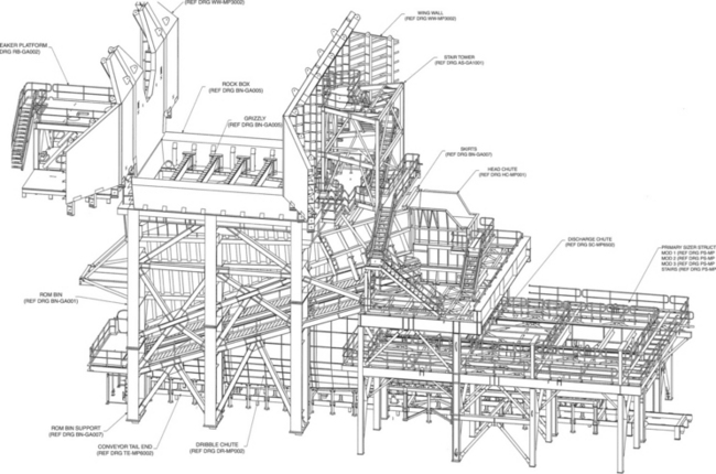
With the use of 3D design, large fabrication shops, transport systems, and large cranes, it is possible to build (and disassemble) the ROM hopper in large modular units. Figure 19.10 shows a typical ROM station with apron feeder and sizer. Figure 19.11 shows a module of the ROM hopper. This unit weighs about 250 t. A typical mine may run the ROM stationing one location for several years. At the appropriate time, a second unit could be built in a new position. Then the old unit can be taken out of service, disassembled, and overhauled to be ready for the next task. Under the right circumstances, the schedule may allow one unit to be used. The move may take say 2–3 weeks.

19.5 References
Alles, R., Stressing of Rubber Conveyor Belts and Its Mathematical Treatment. Bulk Solids Handling, 1982. [March 1982.].
Alles, R. Conveyor Belt System Design Manual. Hannover: Contitech; 1988.
Böttcher, G., Measures Concerning the Slitting Protection of Conveyor Belts with Steel Cables, 1978:357–359. [SonderdruckAusBergbau, August 1978.].
Brown, S. Conveyor Noise Specification and Control. Australia: Proc. of Acoustics 2004 QLD; 2004.
CEMA. 6th Edition Belt Conveyors for Bulk Materials. USA: Conveyor Manufacturers Association; 2005.
Colijn, H., Conners, P., Belt Conveyor Transfer Points. AIME Transactions Volume 252. 1972. [1972.].
DIN 22101. Belt Conveyors for Loose Bulk Materials- Basis for Calculation and Dimensioning. German National Standard: Deutscheslnstitut Fur Normung E.V; 2000.
Dumonteil, P. Outline of a theory of the start-up of the conveyor belt. Mineral Industry Review. 1967, 1967.
Flebbe, H., Dynamic Splice Strength – Design Criterion for Conveyor Belts. Bulk Solids Handling, 1988. [March 1988.].
Funke, H., Dr-Ing, The Dynamic Stress of Conveyor Belt Systems During Start-up and Shutdown, 1974. [Braunkohle, March 1974.].
Funke, H., Dr-Ing, Experimental and Theoretical Investigations for the Design of a Long-distance Belt Conveyor System, 1987. [Braunkohle October 1987.].
Gallagher, D., Technology in Motion for the International Rubber Conference Melbourne, 2000. [Australia.].
Grimmer, K., Beumer, B., Design and Operation of Curve Going Conveyors with Standard Belts, 1972. [Fördern and Heben, March 1972.].
Grimmer, K., Kessler, F. The Design of Belt Conveyors with Horizontal Curves. Bulk Solids Handling. 1992. [October 1992.].
Haddock, K. The Earth Mover Encyclopedia: The Complete Guide to Heavy Equipment of the World. St Paul USA: MBI Publishing Company; 2002.
Hager, M., Simonsen, H., Calculation and Design of Belt Conveyors for Bulk Material, 2000. [Braunkohle. May/June 2000].
Harrison, A. Minimising Transient Stress in Conveyor Belts. IEAUST Mechanical Transactions; 1984.
Hintz, A. Influence of the Belt Structure on the Energy Consumption of Belt conveyor Systems. Doctoral thesis University of Hannover Germany; 1993.
James, G. A Non-destructive Test for Belt Splices. How Good Are Your Splices? Bulk Solids Handling. 12, 1992. [Number 4.].
James, G. Design of a 13.1 Kilometer Overland Conveyor. Bulk Solids Handling. 12, 1992. [Number 4.].
James, G. A Review of Conveyor Take-up Design. Perth: IEUST International Mechanical Congress and Exhibition; 1994. [1994.].
James, G. Simple Rules to Approximate Transient Tensions in Belt Conveyors. Melbourne: Bulkex 2000; 2000.
James, G. Handling Primary Crushed Ore. IIR Conference Brisbane; 2007.
James, G. Holdbacks ‘The Loads Are Shocking. IIR Conference Perth Australia; 2007. [December 2007].
James, G. Conveyor Belt Design for Optimum Efficiency. Singapore: 3rd Annual Bulk Material Handling IBC ASIA; 2010. [2010.].
James, G., Ozolins, I., von Blomberg, H. Mobile Elevator Conveyors. Bulk Solids Handling. 5(6), 1985. [Republished in the Best of Bulk Handling Open Pit Mines & Quarries/ Conveyor Belt Technology book 1986.].
Kahrger, R., A New Mobile Conveyor System for In-pit Crushing. Bulk Solids Handling, 1987. [June 1987].
Lodewijks, G. Rolling Resistance of Conveyor Belts. Bulk Solids Handling. 15, 1995. [Number 1, January/March 1995.].
Lodewijks, G., Two Decades Dynamics of Belt Conveyor Systems. Bulk Solids Handling., 2002.
Mitchell, D., The Development of Movable Conveyor Drive Heads. International Conference on Bulk Materials Storage, Handling and Transportation, 1983. [Newcastle Australia August 1983.].
Neagle, J., Some Design Aspects of a Movable Open Cut Face Conveyor. Bulk Solids Handling, 1983. [November 1983.].
Nordell, L., Ciozda, Z., The Analysis of Starting and Stopping High Strength. High Capacity Belts Using Modern Engineering Tools. 1984. [SME-AIME Annual Meeting 1984.].
Nordell, L., Ciozda, Z., Transient Belt Stresses During Starting and Stopping: Elastic Response Simulated by Finite Element Methods. Bulk Solids Handling, 1984. [March 1984.].
Oehmen, The starting Behaviour of Conveyor Belt SystemsDissertation. Hannover, Germany: Hannover University of Technology, 1959. [1959.].
Oszter, Z.F. Large Capacity Belt Conveyors. Motion Resistance Evaluation Mining Engineering; 1980.
Precismeca. Idler Design Manual Catalogue #101 F. Precismeca Canada circa; 1998. [1998.].
Roberts, A.W., Harrison, A., Hayes, J. Economic Factors Relating to the Design of Belt Conveyors for Long Distance Transportation of Bulk Solids. Bulk Solids Handling. 1985. [December 1985.].
Roberts, A.W., Scott, O.J. Flow of Bulk Solids Through Transfer Chutes of Variable Geometry and Profile. Bulk Solids Handling. 1, 1981. [Number 4. December 1981.].
Steven, R., High Tech Conveyor Development for the World’s Longest Single-Flight Conveyor. Australian Bulk Handling Review, 2007. [Nov/Dec 2007.].
Strzodka, K., Kraus, P., Sangner, R., Mining in Open Pits State of the Art and Outlook. Bulk Solids Handling, 1993. [May 1993.].
Timtner, K., Dr. Ing, Peak Torque Calculations for Backstops SME 1996, 1996.
Timtner, K., Dr. Ing, Load Sharing Methods of Backstops in Conveyor Drive Systems, 1998. [SME 1998.].
Torsten, B., Dimensioning and Application of Belt Conveyors with Intermediate Belt Drive. T-T System. Bulk Solids Handling, 1982. [March 1982.].
Weigel, Th., The Use of Intermediate Drive Units for Belt Conveyor Systems. Bulk Solids Handling, 1982. [March 1982.].
Wheeler, C., Analysis of the Main Resistances of Belt Conveyors. Doctoral Thesis University of Newcastle NSW, Australia, 2003.
Wypych, P. Predicting Bulk Material Flow and Behaviour for Mining and Handling Operations. Perth: Mine Site Bulk Materials Handling Forum IQPC; 2010. [2010.].