
Cleaning of coarse and small coal
Abstract:
Methods for cleaning coal particles greater than 1.0 mm in size are discussed. Water-based technologies include jigs, dense (heavy) medium baths and cyclones, fluidised beds and Reflux Classifiers (RC). Dry-based methods include air jigs, air-fluidised beds and tables and optical/X-ray sorting. Likely future trends in plant design are discussed. Continued improvement in dry-based methods may see them being used more often as a preliminary de-stoning step for coarse particles. Improved water-based technologies will enable an increase in the upper size of the fine coal circuit, from 1 mm up to say 4 mm, which should significantly increase plant capacity.
10.1 Introduction
This chapter discusses the cleaning of coarse and small coal, defined as particles greater than approximately 1.0 mm in size.1 Section 10.1 discusses the layout of a generic coal handling and preparation plant (CHPP) with parallel streams of material in different size fractions, and introduces the technology options available in each size range. Section 10.2 then overviews the basic theory behind density-based separation processes, particularly focusing on the effect of the free-settling factor and how this is influenced by the fluid (medium) density. There is also a brief coverage of the phenomenon of phase inversion in fluidised beds, and differential acceleration in jigging. The final part of the theory section highlights the requirement for a constant incremental ash across all process streams, and the implications of this for circuit optimisation.
Sections 10.3–10.5 are about the various technologies available for coarse and small coal cleaning. Section 10.3 focuses on dense medium separation processes, namely baths and cyclones, their performance, modelling, measurement, control and medium recovery circuits. Section 10.4 focuses on purely water-based gravity separation devices that have the potential to be applied to particles > 2.00 mm in size, namely jigs, Teetered Bed Separators and RCs. Other water-only based devices for treating the fine size fraction are discussed in Chapter 11. Section 10.5 discusses dry separation processes, namely pneumatic jigs, air tables, air-fluidised beds and optical sorting.
Section 10.6 speculates on future trends in the washing of coarse and small coal, and Section 10.7 concludes by listing some important sources of further information.
10.1.1 Generic coal preparation plant
The objective of a CHPP is to remove sufficient mineral matter to meet designated product requirements, with minimal loss of combustible material to the tailings. In doing so, it is usually desirable to minimise the production of fines, given that fine particle processing is much more expensive, and the fine clean coal product and the fine tailings are more difficult to dewater and handle. This philosophy is very different from mineral processing, where fine grinding is used to achieve liberation, and separation is achieved through flotation to meet the required grade and recovery.
Hence, a typical CHPP consists of two to four parallel streams processing different size fractions of material, as shown in Fig. 10.1. The size demarcations between the different parallel streams, and the choice of unit operations, vary. Where it exists, the large-coarse stream (say greater than 50 mm) has traditionally been cleaned using either heavy medium baths or jigs. However, as the size of dense medium cyclones (DMC) has increased, so too has their upper size limit; so the large-coarse stream is now often omitted and all material is crushed down to a specified top size. The small or intermediate size fraction (typically 50 mm down to around 1 mm) is nowadays nearly always cleaned using DMCs, although jigs may still be used when there is little near density material. The fine stream (down to a lower limit of around 0.2 mm) can be treated in a range of technologies. If there is sufficient value to warrant the cost of recovery, then the remaining ultrafine fraction is traditionally cleaned using flotation.

10.1.2 Classification targets
This chapter is concerned with the processing of the coarse and small (also called intermediate) feed size fractions, larger than about 1.0 mm, up to typically 50 mm or even as large as 300 mm. Standard practice in Australia is to break the feed to pass 50 mm before using DMCs. The lower particle size set for the DMC is often about 1.0 mm. However, a finer size might be used, e.g. 0.5 mm, if flotation is the only other separation method employed.
There appears, however, to be a growing realisation that fines classification at 0.5 mm wedge wire to generate a flotation feed is in many instances not the best choice. The wedge wire permits elongated particles larger than 0.5 mm through and, given screen wear, relatively large particles ~ 1 mm are sent to flotation cells. The flotation recovery of these relatively large particles is often very poor; hence vast quantities of fine coal are lost in flotation tailings.
Thus there is an argument that 0.5 mm is too coarse for efficient flotation, which means that a fine stream becomes applicable, say between 0.20 and 1.0 mm. With parallel circuits, the goal is to run them all at constant incremental ash in order to maximise overall plant yield (Luttrell et al., 2003). There is also new interest in running the classifying screen above 1.0 mm. The argument is that less classifying screen area is required, and hence capital investment can be reduced. A further argument is that DMC performance breaks away below 4.0 mm, and increasingly below 2.0 mm. This effect is believed to be greater in large DMCs, but this issue is contested (see Section 10.3.3). This again increases the need for an intermediate stream, now perhaps between 0.25 and 2.0 mm.
10.1.3 Technology options for density separations
There are many different density-separation technologies to choose from. The first decision is whether to use wet or dry separation. Dry separation has numerous potential benefits, including reduced use of water, which is attractive in many arid areas; elimination of the associated costs of product dewatering and water clarification; reduced breakdown of clays and shale; increased product calorific value; and reduced product transport costs. Dry separation technologies for coarse particles include optical or X-ray sorters and pneumatic jigs and tables. For small/intermediate size coal, air tables and air-fluidised beds are feasible. However, dry processing suffers a major drawback in that the separation efficiency of these technologies is currently poorer than that achievable in wet processing. In addition, dry processing has potential problems with dust generation, explosion risks and processing problems if the feed becomes damp.
If wet processing technologies are chosen, then the next decision is whether to use a water-only (autogenous) system or a water-based dense medium (also called heavy medium). The main autogenous processes for coarse and intermediate sized particles are various types of jigs. Particles in the fine size range can be treated in a number of different units, including water-only cyclones, shaking tables, fluidised (teeter) beds for particles up to 3 mm, spirals for particles up to 1.4 mm, and RCs that have been tested at pilot scale up to 8 mm (Galvin et al., 2010b). The ultrafine fraction is usually cleaned using flotation; however, recent laboratory-scale work has found that a dual RC arrangement can produce a de-slimed product down to 0.040 mm (Galvin et al., 2010a, 2010b). The technologies for fine and ultrafine coal processing are described in Chapter 11. Water-only systems avoid the cost and complexity of a medium recovery circuit. However, they usually do not achieve as high a separation efficiency, and the applicable size range is more limited.
If it is decided to use a dense medium, then DMCs become the main process option for the intermediate size range. Although not as common today, dense medium baths and jigs (with or without a dense medium) may still be economically justified when the top size is large, perhaps up to 300 mm, as for instance in an initial de-stoning step when there is a large amount of out-of-seam dilution material that can easily be removed.
Ultimately, the decision concerning the plant top size, the demarcation between different size fractions, and whether to introduce a dense medium circuit, depends on the amount of near density material in the feed and the requirements of the customer. Dense medium processes out-perform other separation processes when there is a significant amount of near density material present (Osborne, 1988). In Australia, where the bulk of coal is mined for export, the current choice is nearly always to opt for dense medium processes (MacKinnon and Swanson, 2010). Chapters 14 and 17 discuss the topic of optimal flow sheet design in more detail.
10.2 Theory
This section analyses some theoretical aspects of gravity separation, in order to explain the fundamental reason for the markedly different performance of dry, water and dense-medium based separation equipment. The significance of having multiple parallel circuits compared to a single large unit is also briefly discussed.
10.2.1 Principles of gravity separation
Many separation processes are based on the differences in settling velocity of high density and low density particles. An upwards current of fluid (gas or liquid) preferentially elutriates the low density particles in the overflow, leaving the high density particles to exit in the underflow. For spherical particles, there are well-established equations for predicting the terminal free-settling velocity ut as a function of particle diameter d and density ρp, fluid density ρf and viscosity μ, and gravitational acceleration g (e.g. Rhodes, 2008). These depend on which settling regime the particle is in. In the Stokes’ law regime, where viscous forces dominate (Ret = utρfd/μ < 1):
Numerous empirical correlations are available for the intermediate regime (1 < Ret < 500). For instance, one based on Vance and Moulton (1965) is:
In the Newton’s law regime (500 < Ret, < 105):
Empirical correlations that cover the full range up to Ret, < 105 are also available (e.g. Zigrang and Sylvester, 1981; Turton and Clark, 1987), including relationships applicable to non-spherical particles (Haider and Levenspiel, 1989). In general, we can write that:
where for Stokes’ regime, k = 2, m = 1 and for Newton’s regime, k = 0.5 and m = 0.5.
In general, particles are present as concentrated suspensions where hindered settling effects reduce the settling velocity of particles. The hindered settling velocity uths can be estimated by the following empirical equation (Asif, 1997):
where n is the Richardson–Zaki coefficient, which varies from 2.4 for coarse particles to 4.6 or more for fine particles, and can be predicted by various empirical relationships (Richardson and Zaki, 1954; Khan and Richardson, 1989). Note that for the case where all the particles in the suspension have the same density, the term in brackets simplifies to e, the suspension porosity, and so this equation reduces to the more well-known Richardson–Zaki equation for single-component suspensions uths = utεn. However, the above form is more general, as it can also be applied to multi-component systems.
Settling velocity depends on both particle size and density. This dual dependence limits the maximum particle size range that can be separated according to density using any particular fluid. This size ratio dA/dB is known as the free-settling ratio of the two materials A and B, i.e. the ratio of particle size that results in the same settling velocity for two particles of different density ρA and ρB (Wills, 1997). From Equations [10.1]–[10.5], this ratio is given by

For dilute systems where ρsusp = ρf, this simplifies to the expression given by Wills (1997):

where m/k = 0.5 for small particles (in Stokes’ regime), m/k = 1 for large particles (Newton’s regime) and 0.5 < m/k < 1 for particles of intermediate size (approximately 0.05 to 5.0 mm for coal in water).The ratio of the density differences in Equation [10.7] is called the concentration criterion (Taggart, 1945). It is desirable to be able to separate as wide a size range of material as possible in a single unit i.e. for dA/dB to be greatly different from 1.0. This is inherently easier with coarse particles that settle in the Newton’s law regime where m/k is largest and so the particle settling velocity is relatively more sensitive to particle density. For instance, Table 10.1 shows that to separate a dilute suspension of coal (R.D. = 1.4) from mineral matter (R.D. = 2.0) in water (R.D. = 1) Equation [10.7] gives dA/dB = 2.5 for particles in the Newton’s law regime, whereas dA/dB = 1.8 in the intermediate regime. In addition, the faster settling rates of coarse particles also make these separations occur more quickly and thus reduce the required residence time in the process.
Table 10.1
Sample results for the free-settling ratio for separating solids of relative density ρA = 1.4 and ρB = 2.0 in a fluid of density ρf and suspension of density ρsusp
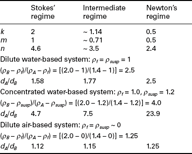
As the suspension density ρsusp increases, the free-settling ratio also increases. For instance, for coarse particles in Newton’s settling regime, if there is a concentrated suspension involved, say ρsusp = 1.2, then Table 10.1 shows that dA/dB = 23.9, a dramatic increase from 2.5. For small particles in the intermediate settling regime, dA/dB = 7.5 for a concentrated suspension. This is consistent with the roughly eight-fold size range from around 0.25 to 2.00 mm typically processed in fluidised beds (e.g. Galvin et al., 1999).
This autogenous dense medium effect is promoted in density-based separations by generating high suspension densities (typically > 30 wt%), whereas size classification processes are usually carried out at low pulp densities (typically < 10 wt%). Note here that it is the suspension density inside the unit that is important, not the pulp density of the feed. Operating at higher pulp densities does lower separation velocities, but this is usually compensated for by the increase in the solids throughput. It is important, however, to minimise the build-up of slimes in any circuit because they disproportionately increase the viscosity, thus further reducing settling velocity and in turn throughput.
Equations [10.6] and [10.7] also explain why the purely air-based elutriation systems used for dry coal processing have an inherently poorer separation efficiency due to the low density of air (R.D. ~ 0). For the previous example, dA/dB = 1.25 for dilute coarse particles and dA/dB = 1.15 for intermediate sized particles (Table 10.1).
If the (effective) fluid density is between that of the two species being separated (ρA < ρf < ρB), then there is an infinite free-settling ratio, i.e. given enough time, all the low density material should float to the surface and the high density components should all sink to the base, regardless of their size. Herein lies the major attraction of using a dense medium – it gives the theoretical potential to separate across the full range of particle sizes in a single unit. The major drawback of a dense medium process is the added cost and complexity of the medium recovery circuit and replacing medium losses. The higher density and viscosity of the medium does reduce the speed of particle settling, so longer residence times may be required.
When the dense medium is a pseudo-fluid created by using a suspension of fine particles (e.g. –60 μm magnetite), then as particles approach the same size as the medium, they no longer ‘see’ the suspension as a continuous fluid, but rather as discrete particles, and hence the effective fluid density used for buoyancy calculations returns to being that of the interstitial fluid (Bicknell and Whitmore, 1967; Batchelor, 1982).
When concentrated suspensions of particles are fluidised, their interactions can lead to complex behaviour. Figure 10.2 illustrates the phenomenon known as phase inversion, which can occur with mixtures of small dense particles and large low density particles. Initially at low fluidising velocities, the mixture segregates, with the small high density particles residing at the bottom of the bed and the large low density particles residing in the upper layer. At an intermediate fluidising velocity the two materials can form a mixed layer, and then at higher velocities they re-segregate, but this time with the large low density particles at the base and the small dense particles above (Moritomi et al., 1982).

10.2 Schematic of phase inversion phenomenon in a mixture of small high density particles (![]() ) and large low density particles (
) and large low density particles (![]() ): (a) At low velocities the small dense particles form a layer beneath the large low density particles; (b) at intermediate velocities a mixed layer forms; (c) at high velocities the small dense particles form a layer above the large low density particles.
): (a) At low velocities the small dense particles form a layer beneath the large low density particles; (b) at intermediate velocities a mixed layer forms; (c) at high velocities the small dense particles form a layer above the large low density particles.
In systems such as illustrated in Fig. 10.2, the small high density particles have a lower terminal free-settling velocity than the coarse ones. Hence it might be expected that they would always be elutriated before the larger low density particles, and hence it should be impossible to capture the coarse low density particles without contamination by these dense fines. However, provided the fluidisation velocity is not too high, Fig. 10.2a shows that the coarse low density particles can be elutriated first without contamination by the high density fines. It is therefore important not to operate too far above the minimum fluidisation velocity. This shows how taking advantage of the autogenous dense medium effect can extend the range over which efficient density separation is possible.
The free-settling ratio provides a simple measure of the particle size range that can be used to achieve a given density-based separation. However, systems can be physically constructed in various ways that help to suppress the effects of particle size and hence increase the size range that can be separated. In spirals, a circulating transverse current is generated in the thin film. The high shear rate in this film selectively suspends low density particles and lifts them to the perimeter (Sanders, 2007). In narrow channel RCs, fine particles lying on the channel wall experience less upwards velocity than coarse particles due to the laminar flow profile, so the influence of particle size is reduced (Galvin et al., 2009, 2010). A similar principle is also at work in shaking table concentrators, where large particles experience more of the fluid velocity than fine particles. Chapter 11 also discusses these mechanisms.
In jigs, the influence of particle size is suppressed by allowing particles to settle only over short distances. A particle in a liquid experiences a downwards gravitational force Fg = ρpVpg and an upwards buoyancy force Fb = ρfVpg, where V is the volume of the particle. For particles at rest, the drag force is negligible, and so their initial rate of downwards acceleration a is given by Newton’s second law:
The key feature to note in Equation [10.8] is that the initial rate of acceleration is independent of particle size and depends only on particle density. This forms the main basis of the separation mechanism in jigging operations, where the particle bed is repeatedly expanded and then the particles are allowed to settle over short distances. However, there are also other mechanisms at work in jigs, such as the selective percolation of fine particles through beds of coarse particles (Wills, 1997).
10.2.2 Circuit optimisation
One feature of coal preparation plants that is not shared with most mineral processing operations is the existence of parallel streams containing different size ranges of material (e.g. coarse, intermediate and fine). Each size range will generally have a different head ash and degree of liberation; so the question naturally arises as to what target separation density (incremental ash, incremental calorific value or boundary ash) should be used in each circuit. It might be thought that each stream should be operated to give the same cumulative ash as the target final product cumulative ash. However, this strategy is not optimal. It can be shown that if perfect separations can be obtained in each circuit, the maximum overall yield is obtained when each parallel circuit is operated at the same incremental ash cut point, regardless of the degree of liberation of the material (e.g. Luttrell et al., 2003).This topic is also discussed in Chapter 17.
This principle of aiming for the same incremental ash in each circuit also applies when a single size range of material is split and treated in multiple parallel processes. The maximum yield is obtained when every unit operates at the same incremental ash (density cut point). As the number of parallel processes increases, it becomes more difficult to operate them all at the same cut point; so the theoretical benefit of the sharper individual partition curves obtained in smaller units may often be outweighed by the loss of overall circuit efficiency if these units all run at slightly different cut points. This is a key issue when considering the relative merits of, say, a bank of many spirals or multiple small diameter DMCs versus a single unit such as a teeter bed separator, RC or large diameter DMC. It is invalid to base comparison on the performance of a single spiral or small DMC, since a bank of 20 or more units will inevitably have a lower overall performance. It is noted, however, that fluidised bed devices exhibit a shift in density cut point with particle size, so the single large separator is not always better.
The goal of constant incremental ash in all circuits is an optimum only for the case of perfect separations. In reality, since the sharpness of separation of units may vary, modelling using partition curve and washability data provides the best basis for decision making and optimisation. The Écart probable error, Ep (Wills, 1997), is therefore an important measure, but the tail of the partition curve can also be an important factor. In practice, the exact cut point of every circuit may not be known, so targeting specific cut points can be difficult. This is particularly the case for the large DMCs, which are often processing the majority of the plant feed. Hence, in practice, it may be prudent to hold the DMCs constant and use the intermediate/fine gravity circuits to respond to any short-term adjustments in production requirements. This approach could make teetered bed separators or RCs attractive, since they can be controlled remotely.
10.3 Dense medium separation
This section discusses dense medium separation, including the choice of medium, the two main types of dense medium unit operations, baths and cyclones, and the associated medium recovery circuit. The performance, operation, modelling and control of dense medium cyclones is the major focus, as these are the most commonly used process.
10.3.1 Choice of medium
The first patented dense medium process proposed dense solutions of various chloride salts. Later patents appeared describing the use of chlorinated hydrocarbons. These processes suffered from high liquid losses and, in the case of chlorinated hydrocarbons, the resulting toxic contamination of the environment. In 1917 the Chance process was the first to use a suspension of sand and water. The Conklin process in 1922 was the first to trial the use of magnetite, and the Tromp process in 1938 became the first to commercially employ magnetite suspensions as the dense medium (Leonard, 1979). Today, magnetite is used in most dense medium processes in the coal industry.
Magnetite can be used to form dense media with densities in the range 1.2–1.8 R.D. More dilute suspensions become unstable, whereas higher density suspensions are too viscous to enable efficient particle separation and medium recovery (Osborne, 1988). Typical magnetite particle size is in the range 10–60 μm. Again, if the particles are too large, then the suspension is unstable, and if they are too fine then the medium becomes too viscous. An ‘unstable’ medium is generally defined as one in which the density difference between the underflow and overflow medium is greater than about 0.4 R.D. (Sanders, 2007).
It is desirable to use coarser media where possible, as this is easier to recover and gives a lower viscosity. Use of a coarser media may be possible in a large diameter DMC, since the centrifugal forces are lower, so the medium stability is not as much of a problem (Engelbrecht and Bosman, 1995). This is another motivation for raising the aperture size in the screens classifying material to the intermediate circuit. However, achieving low density cut points can be a problem with coarse media.
10.3.2 Dense medium baths
There are many dense medium bath type designs. Two illustrative examples are shown in Figs 10.3 and 10.4. The basic concept is simple. Feed is added to a bath of dense medium and time is allowed for the dense particles to sink to the base and the low density particles to float. Paddles of some sort are used to scoop the floats from the surface and a scraper recovers the sinks from the base. The medium itself will tend to segregate over time, so sediment has to be regularly removed, re-suspended and then returned to the bath. Variations include simultaneously using two different medium densities in order to generate an additional middlings fraction (Fig. 10.3). Rather than relying on mechanical scrapers and paddles, which are prone to wear in such an abrasive environment, some designs place the bath inside a horizontal rotating drum with flights on the periphery so that the rotation of the drum is used to reclaim the sinks fraction (Fig. 10.4).
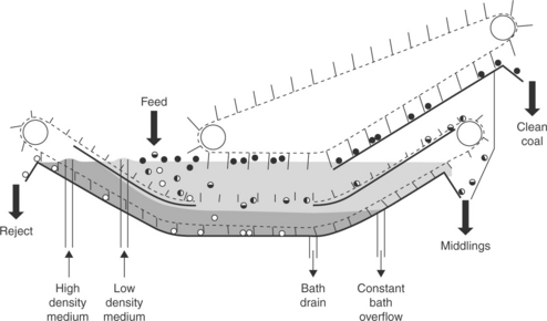
10.3 Tromp bath. (Source: Adapted from Sanders, 2007.)
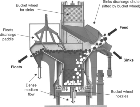
10.4 Schematic of Teska drum, an example of rotating drum type design. (Courtesy MBE Coal & Minerals Technology GmbH.)
Most baths can handle feed particles exceeding 200 mm in size at capacities of several hundred tonnes per hour or more, depending on the size of the bath. Dense medium baths do not, however, have as low Ep values as DMCs, due to the reduced separating forces, and so are not usually used for feed below 10 mm in size. Large diameter DMCs can now handle material 100 mm or larger; so there has been a tendency to dispense with baths and crush all feed to down to a size where it can be treated in the DMC circuit.
Baths do, however, have some advantages over DMCs. They have lower operating costs due to the lower pressure and reduced medium losses. They can also operate at much lower density cut points than DMCs, as the reduced forces mean that dilute medium remains stable. Hence, baths remain competitive in cases requiring low density cut points, or where the coal is hard and thus expensive to crush down to the size required for a DMC (Bethell and Luttrel, 2003).
10.3.3 Dense medium cyclones (DMCs)
DMCs were developed by the Dutch State Mines (DSM) in the 1940s and sold commercially by Stamicarbon. Since their introduction, they have steadily displaced jigs as the preferred unit operation for treating small (intermediate) feed sizes. As they have increased in size and so are able to handle larger feed particles, they have in many instances also started to displace dense medium baths. In the Australian coal industry they now typically treat 60–85 % of all plant feed (Atkinson et al., 2007; Sanders, 2007).
Figure 10.5 shows the standard DSM design. The most important variable that controls both throughput and upper size limit is the cyclone diameter Dc. The feed inlet diameter Di is typically 0.15–0.25 times the cyclone diameter. The vortex finder (outlet) diameter Do is typically 0.43–0.5 times the cyclone diameter. The apex (spigot) underflow diameter Du is generally 0.3–0.4 Dc.
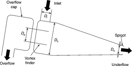
10.5 Typical dense medium cyclone of the DSM design. Not to scale. Dc = cyclone diameter; Di = inlet diameter, Du = underflow diameter; Do = overflow diameter.
There are also many variations of the DMC concept that use a combination of dense medium and centrifugal forces. Some have cylindrical bodies, such as the Bretby Vorsyl, Dynawhirlpool, Tri-Flo and Larcodems designs (Sanders, 2007). Other differences from the DSM design include the geometry of the feed inlet (tangential, involute, etc.) and in some cases the feed and medium are added at separate locations.
The optimum operating pressure of a DMC is usually quoted as being at a slurry head of around 9 Dc. It is important to measure and keep this value stable since fluctuations in pressure cause the velocity to vary, which has a large impact on cyclone performance. Variable speed pumps are often used so that loss in performance due to wear can be compensated for by increased pump speed. Note that this 9 Dc figure is for a standard DSM geometry where Di = Dc/5. If a high capacity unit is being used with a wider feed inlet diameter, there is a lower feed velocity and hence a drop-off in performance occurs. Thus Meyers and Sherritt (2010) stress that one should use the ‘DSM equivalent Dc’, defined as 5 Di. to calculate the required feed pressure.
The optimum medium to solids feed ratio (expressed on a volume basis) is generally between 3:1 and 5:1 for coal. Here the term ‘medium’ refers to the magnetite suspension, before addition of any coal. For instance, if 85 t/h of coal from the screens with an average R.D. of 1.45 is mixed with 350 t/h of magnetite suspension with R.D. 1.38, then the medium-to-coal volumetric ratio is [(350 t/h)/1.38]/[(85 t/h)/1.45] = 4.3. Below the lower end of this range of 3:1, there is too much crowding of coal particles and efficiency deteriorates rapidly. At the upper end of this range, above 5:1, the efficiency of separation becomes very good, at the expense of capacity. This situation may be justifiable in cases where there is a large amount of near density material.
The medium itself undergoes a certain amount of separation inside a DMC, which results in the underflow having a higher density than the overflow. This density difference in the outlet medium streams is called the differential. A small amount of differential is actually helpful, as it creates an internal recirculation of near density material. The longer residence time of this middling material may promote breakage and hence better liberation, and thus give better efficiency (Luttrell et al., 2005). However, if the differential becomes larger than about 0.4 R.D., then there is too much build-up of near density material and the inside of the cyclone becomes choked. This condition results in ‘surging’, the periodic dumping of material out through the spigot, which results in the loss of entrained low density material (Sanders, 2007).
This problem is worse when attempting separations at low density cut points, since at low concentrations the medium experiences less hindered settling and hence separates more easily. So, although the presence of slimes in a circuit is usually undesirable, dense medium separations conducted at low separation densities can actually benefit from the presence of additional slimes viscosity. However, control of this condition can be difficult due to problems in measuring the relative presence of the slimes and magnetite (Firth et al., 2011).
In baths the density cut point is usually quite close to the medium density. However, in DMCs the density cut point is usually 0.1–0.15 R.D. higher than the density of the medium, particularly for finer particle sizes. This difference, called the density offset, is usually positive although in unusual cases, such as when an extremely large spigot diameter is used, it can be negative (Williamson and Davis, 2002). This offset is controlled by the differential in the medium density between underflow and overflow, and also by the relative proportion of flow exiting via the underflow and overflow.
Figure 10.6 shows typical Ep values for a 0.75 m diameter DMC as a function of density cut point and particle size. Ep increases with density cut point due to the higher concentration medium suspension also having a higher viscosity. Above 4 mm in size, performance is almost independent of particle size. However, below 4 mm Ep starts to deteriorate. This is because fine particles have lower settling velocities, and so take longer to report to the correct product stream.
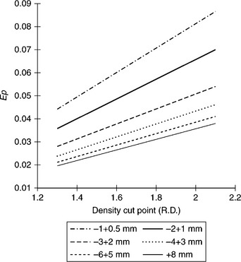
10.6 Relationship between Ep, cut point RD50 and particle size for a 750 mm diameter DMC. (Source: Adapted from Sanders, 2007.)
Table 10.2 presents the capacity of the standard design DMC as a function of cyclone diameter. By the 1980s use of 710 mm diameter DMCs was common, and since the mid 1990s large diameter (1000 mm and larger) have been almost universally employed in new and upgraded plants (Atkinson et al., 2007). There is a continuing trend towards even larger DMCs, for example 1.5 m diameter. These larger units have increased capacity (high capacity designs can exceed 1000 t/h) and can also handle larger top sizes, exceeding 100 mm. There are two main benefits in moving to larger cyclones. First, although there may be a deterioration in performance, and perhaps even breakaway at a size smaller than say 4.0 mm, the overall performance for the plant may still be improved. The reason is that with fewer units, it becomes easier to operate all units at the same incremental ash, which optimises circuit performance (Section 10.2.2). The second benefit of larger units is that they enable the inclusion of coarser material into the intermediate stream, thus potentially eliminating the need for a separate coarse circuit.
Table 10.2
Typical performance of standard DSM design DMCs for coal
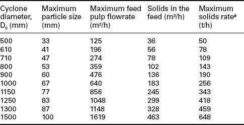
#Estimated assuming 1.4 R.D.
Source: Sanders, 2007.
There are ‘High Capacity’ designs which have longer cylindrical sections. These can be used to obtain a greater throughput at the same efficiency, or alternatively to give improved separation performance at the same flowrate due to the longer residence time. However, with this longer residence time comes an increased risk of medium instability (Williamson and Davis, 2002). It is also possible to increase the maximum particle size by increasing the diameter of the feed and outlet diameters (Engelbrecht and Bosman, 1995).
There has been significant concern that the separation performance of large cyclones deteriorates very rapidly for particles less than 4 mm in size (e.g. Englebrecht and Bosman, 1995; Clarkson and Holtham, 1998; Weale and Swanson, 2002). The size below which performance starts to rapidly deteriorate is called the breakaway size. How rapidly the performance of large cyclones deteriorates for the finer particles is the subject of some debate, due to the difficulty in reliably sampling at these large flow rates. Atkinson and Swanson (2007) found that it was cut point drift, rather than deterioration in Ep, that caused loss in performance at finer sizes. Vince (2008) argues that the uncertainty in much of the published partition data for fine particles is so high as to make the results inconclusive. He also puts forward evidence to suggest that significant levels of breakage occur in many cases.
Meyers and Sherritt (2010) have recently found that provided the feed pressure and medium-to-coal ratio are optimised, no excessive ‘break away’ in performance occurs for large diameter DMCs. Their analysis, presented in Fig. 10.7, shows that large 1.45 m diameter DMCs can obtain Ep values across the full range of particle sizes down to 2.0 mm, just as good as smaller 1.3 and 1.0 m diameter units.
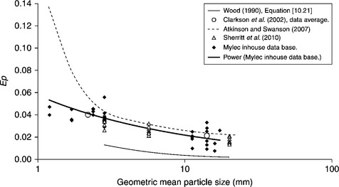
10.7 DMC Ep versus geometric mean particle size for a range of cyclone diameters. Wood (1990) equation was based on Dc from 0.1 to 0.8 m. Clarkson (2002) and Atkinson and Swanson (2007) data is for Dc from 0.7 to 1.3 m. Sherritt et al. (2010) data is for Dc = 1.45 m. Mylec in house data is for Dc from 0.9 to 1.3 m. (Source: Adapted from Meyers and Sherritt, 2010.)
It should also be noted that partition curves become progressively more asymmetrical with increasing cyclone diameter and frequently have tails. Hence Ep alone does not give the full picture of how performance varies. The Error Area Ea is often suggested as giving a better overall picture of performance (Weale and Swanson, 2002; Williamson and Davis, 2002). The partition curves for different size particles frequently pass through a common point, the pivot point (Fig. 10.8), which approximately corresponds to the medium split ratio (Clarkson and Wood, 1991). This is due to the tendency of fine particles to follow the medium flow. This results in a shift in the cut point to higher densities as particle size decreases (cut point drift). Together with the worsening Ep at lower sizes, this behaviour further contributes to a reduction in overall plant performance, as not all size fractions are being cut at the same incremental ash. This gives additional incentive to raise the upper size of the fine size fraction and treat these fines in a separate circuit.
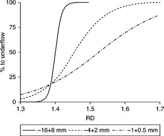
10.8 DMC partition curves for three different size fractions showing the 'pivot point' phenomenon. (Source: Adapted from Wood, 2004.)
As well as DMCs becoming larger to treat coarser feed at higher tonnages, there has also been interest in using banks of smaller DMCs to treat fine coal size fractions. Some of the early DSM circuit designs were for cleaning coal down to 0.15 mm in size (Osborne, 1988). DMCs offer higher efficiency and better cut point control than spirals. Historically, the main reason why they have not been widely adopted is the cost of poor magnetite recovery. However, Lundt and de Korte (2010) report on recent plant upgrades at a South African mine where a two-stage DMC circuit has been installed to treat fine coal down to 0.10 mm in size. This has been running effectively with magnetite losses of only 1.3 kg per tonne product, which is not much larger than typical DMC circuits for intermediate and coarse coal (Section 10.3.4). Chapter 11 discusses fine coal cleaning options in more detail.
DMC modelling and prediction
Modelling the complete performance of DMCs from first principles is a challenging exercise, due to the complex turbulent flow pattern of the continuous liquid phase, the presence of an air core, and the large number of medium and coal particles of varying size and density. The earliest models of DMCs were by necessity empirical or semi-empirical in nature (e.g. Wood, 1990; Napier-Munn, 1991). However, there is a growing trend towards larger DMCs for which not only is it difficult to obtain good experimental data, but it is also expensive to test different design modifications. The reliability of extrapolating from smaller scale work is also uncertain. Hence, it is desirable to have robust, fully theoretical models that can accurately predict DMC performance.
Empirical-based models
One of the best known examples of a comprehensive empirical-based DMC model is that developed by Wood (1990) in his PhD thesis at the Julius Kruttschnitt Mineral Research Centre (JKMRC), Australia. This model consists of various sub-models that must be solved in series to obtain full predictions and has formed the basis of many simulations (e.g. Barbee et al., 2005). Note that improvements over the years have led to alterations in the exact values of some of the coefficients and powers in these model equations.
The first sub-model is a single equation to estimate the volumetric feed flowrate Qf (L/s), based on the cyclone diameter Dc (m), underflow (spigot) diameter Du (m), overflow (vortex finder) diameter Do (m) and feed pressure (head) H measured in number of cyclone diameters head of feed medium i.e. the dimensionless value H = P/(ρmedgDc) where P is the feed pressure, ρmed is the density of the medium suspension and g is acceleration due to gravity:
The second model calculates the medium split. Initially the split is estimated on the assumption there is no coal feed:
where Quz and Qfz are the underflow and feed volumetric rates, in the absence of any coal. Hence:
Note that Equations [10.11]–[10.12] assume Qf = Qfz, i.e. that the feed rate is not influenced by the coal loading.
These values must then be adjusted on the basis of the volumetric split of coal to the two product streams. Initial estimates of the solids volumetric flowrates to floats and sinks, Qos and Qus respectively, have to be made on the basis of the yield-ash curve for the coal feed, the target cumulative ash, and estimated densities of the floats and sinks product solids. If desired, a more accurate result can be obtained by iteration, i.e. using the final predicted partition performance to calculate the mass of coal in each density fraction that reports to each stream, and then converting this to volume by dividing by the density, and summing to give the total volume of coal in each stream (Luttrell et al., 2005). Once these have been estimated, then the medium flow to underflow is:

and hence it follows that the medium volumetric flow rate to overflow is:
Then the actual volumetric split of feed medium Qfm to the underflow Qum is found from:
The third sub-model predicts the underflow medium density ρum (R.D.) based on the feed medium density from:

where PRR is the Rosin-Rammler intercept of the magnetite medium size distribution.
The fourth sub-model predicts the overflow medium density ρom (R.D.)
The remaining sub-models concern the partition performance of the DMC. Coarse (+ 4 mm) particles have a density cut point given by
The separation relative density of particles of size d (mm) is given by:
The Ecart Probable (R.D. units) for particles of size d(mm) is given by:
It is notable that this equation has no dependence on cyclone size. Modified versions of this equation that include the effect of Dc have been included in a more recent work (e.g. Luttrell et al., 2005). See also Fig. 10.7.
The partition number PN (wt%) for any size-density class is then given by:

Note that Equations [10.9]–[10.21] are only for the ‘standard’ DSM DMC design, in which the ratio of inlet diameter to cyclone diameter is fixed at Di/Dc = 0.2.
Simulation models
Various analytical models have been developed over the years to attempt to predict DMC performance. These involve consideration of various effects, such as centrifugal forces, particle residence time, fluid drag, and turbulent diffusion (e.g. Clarkson and Wood, 1990; Hu et al., 2001). Whilst these are useful for explaining trends in the data, their many simplifications inevitably mean that they do not give accurate predictions of actual DMC performance. Hence, they have to be adjusted using empirical data (e.g. Hu and Firth, 2010). However, this then means that their validity under conditions outside the range to which they were fitted is uncertain.
Complete models, which take into account every single fluid–particle and particle–particle interaction, are still beyond present computational capacities. However, in the last two decades there have been significant advances towards fully theoretical computational fluid dynamics simulations of DMC behaviour by several different research groups (e.g. Suasnabar and Fletcher, 1999; Narashima et al., 2007; Wang et al., 2011).
For instance, Yu and co-workers (Chu et al., 2009; Wang et al., 2011) have developed a DMC model based on computational fluid dynamics (CFD) models to establish the velocity distribution of the slurry and position of the air core. They assume a continuous, homogenous fluid of uniform density and viscosity. In the second step, the transport of six different size fractions of magnetite particles is modelled to establish more detailed density and velocity distributions within the slurry phase. In the third step, the motion of individual coal particles is modelled using Discrete Element Modelling (DEM), which includes fluid–particle, particle–particle and particle–wall interactions. The two-way coupling of particle behaviour influencing fluid flow has not yet been achieved, but is the subject of ongoing work.
These CFD-DEM simulations take several months of computing time; so a desk-top platform was developed using empirical fits to the theoretical model predictions (Vince and Yu, 2010).This approach enables the partition performance and medium split to be predicted for dilute systems. This advanced form of modelling has the potential to greatly enhance our understanding of the dynamic behaviour of DMCs and lead to improvements in DMC design and operation.
DMC measurement and control
Changes to plant feed and operating conditions such as pressures, flowrates, medium density and medium-to-coal ratio, all impact the performance of DMCs. As these units process such a large fraction of the plant throughput, it is important to monitor, control and optimise their performance.
A fundamental requirement for process control is reliable measurement of performance. One of the major problems with large DMCs is the difficulty of sampling the input and output flow streams to establish this performance. It is inherently very difficult to collect representative samples of sufficient size when there is such a large flowrate, and the particle size range is so broad. In addition, the overflow and underflow can usually only be sampled as they come off the magnetite recovery screens. So the lower size limit at which performance can be reliably analysed is for particles that do not pass this screen, which when account is taken for wear, may be several millimetres. Hence, it is important to establish protocols for effective sampling around large DMCs (Atkinson et al., 2007).
An alternative is to use density tracer particles to measure partition performance (e.g. Hu et al., 2001). These give very rapid results, but have traditionally been limited to fairly coarse tracers (e.g. > 30 mm) because of the difficulty of manually recovering smaller tracer particles from the vibratory screens. However, there are now light-weight permanent magnets commercially available that can be installed above drainage and rinse screens to recover magnetic tracer particles down to 2 mm in size (Partition Enterprises, 2011). This technology is already used in a few diamond plants, but has not yet been adopted in any CHPPs. There is also ongoing work using radio frequency identification (RFID) tags in tracers, which enables their detection without the difficulty of the recovery process, although this means the tracers must then be considered single-use consumables (e.g. Barbee et al.,2008).
Another important requirement for controlling DMCs is accurate measurement of the medium density. For many years densities were measured by dip tubes recording differential pressure and/or Dp cells. These methods were then replaced by nucleonic (or nuclear) density gauges. These measure the proportion of solids contained in the medium, which is then converted to a density based on prior calibration with standards, which are often calibrated using a Marcy gauge, which may not be reliable. If the medium is contaminated with non-magnetics, then a false reading will result (Osborne, 1988). Nucleonic devices also pose safety concerns.
Hence there is interest in moving away from nucleonic density gauges. More sophisticated approaches are being considered, but these require good sampling and maintenance of the dense medium suspension. Firth et al. (2010) report on the use of electrical impedance spectrometers to measured medium density and composition. Cavanough et al. (2008) and Purdon and Gibson (2012) have had some success inferring density from highly sensitive measurements of magnetic susceptibility; however, further work is required before this can be commercialised.
It is often important to be aware of the impact of fine mineral matter or clays on the medium. If the magnetite recovery process is inefficient the medium may develop higher levels of mineral matter which, for a given density, would increase the solids volume fraction and hence viscosity and in turn reduce the carrying capacity of the medium, i.e. coal feed rate. Density measurement based on magnetic susceptibility fails to account for the presence of slimes (Firth and O’Brien, 2011) but, used in conjunction with a nucleonic gauge, allows the slime content to be quantified.
Once reliable online measurements of medium density and other process performance indicators have been established, these then need to be incorporated into an effective control system. This is the focus of ongoing research, and initial results suggest that there is significant scope for improving performance (Addison et al., 2010; Firth et al., 2010). Aspects of plant control and optimisation are discussed further in Chapter 17.
10.3.4 Medium separation and recovery circuits
The medium recovery circuit is an important component of a dense medium process. A typical layout is shown in Fig. 10.9. Undiluted medium is drained from the initial portion of both the product and reject screens, and sent directly to the correct medium sump. The remainder of the medium is removed by adding rinse water to the latter part of both the product and reject screens. The medium is then recovered from this dilute stream by a magnetic separator. The non-magnetic fines are purged from the circuit. The concentrated medium recovered by the magnetic separator is sent to an over-dense sump. From here it is returned to the correct medium sump, with an appropriate amount of fresh water added. The feed coal and medium must be mixed in the feed sump in such a way that the coal does not start to separate in the sump. This is usually done with some sort of draft tube in which the feed is mixed with part of the medium at high velocity, and the rest of the medium is added around the periphery.
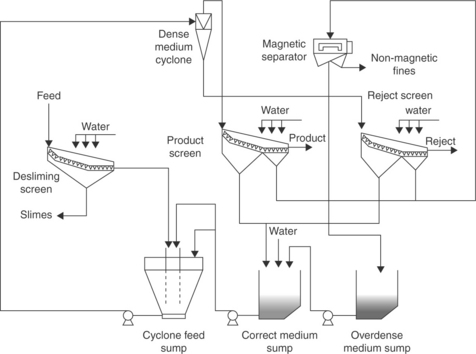
10.9 A typical dense medium cyclone circuit featuring draft tube design feed sump. (Source: Adapted from Sanders, 2007.)
Medium losses represent 10–20 % of the operating costs of a dense medium circuit (Sripriya et al., 2006). Loss rates depend on both the medium size and the coal size. Medium is recovered more easily from coarse coal, and the medium is also easier to drain if it consists of coarse particles. For bath circuits, typical losses are in the range 0.1–0.2 kg per tonne of feed solids. For DMC circuits, losses increase to 0.25–1.0 kg/t (Sanders, 2007).
10.4 Wet gravity separation
This section considers water-based separation devices that can effectively separate particles greater than 2.0 mm in size. For other water-based methods, see Chapter 11.
10.4.1 Jigs
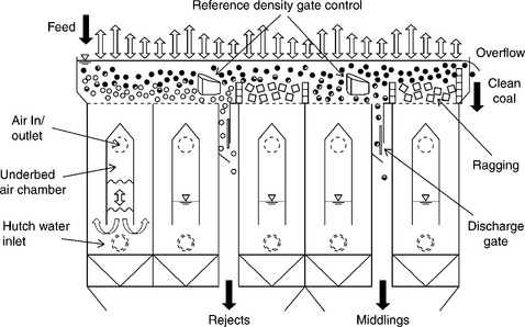
Jigging is one of the oldest forms of coal and mineral beneficiation. In a jig, fluid is pulsed through a bed of solids to cause cyclic expansion and contraction. As a result, the dense particles stratify to the base and the low density particles to the top of the bed. Common versions include the Baum and Batac designs (Figs 10.10 and 10.11), where the bed is supported on a fixed screen and the fluid motion generated by air pressure, either in a side chamber (Baum) or from underneath (Batac). A single jig can treat very large particles (over 200 mm) at capacities greater than 700 t/h (Sanders, 2007).
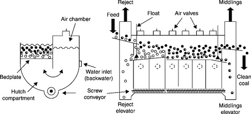
10.10 End and side views of a Baum jig. Not to scale. (Source: Adapted from Osborne, 1988.)
Some recent jig designs, such as the ROMJIG and Gekko Inline Pressure Jig, have returned to the mechanism used in the original hand-operated jigs where the solids were placed on an oscillating screen, rather than having a fixed screen with the water pulsed up and down. In the Gekko Inline Pressure Jig the entire process is enclosed to eliminate the air–water interface and thus prevent disturbances from surface waves. These jigs are most effective at larger sizes. Recent studies have shown that this jig can process feeds down to 0.25 mm in size; however, there is strong variation of density cut point with particle size (Vince et al., 2007, 2010).
Jigs offer greater simplicity and lower capital and operating cost than dense medium circuits. Jigs were the dominant means of treating coarse coal up until the 1970s (Leonard, 1979). However, they do not perform as well as DMCs when there is a significant amount of near density material. As a result, the use of jigs has declined and DMCs have become the dominant technology. However, jigs may still merit consideration in applications where the target ash is relatively high, or where there is good liberation at a coarse particle size (little near density material) and/or when capital funds are limited.
10.4.2 Extending fine gravity methods up to coarser sizes
Most of the water-based methods discussed in Chapter 11 that are used for treating fine coal are unsuitable for processing particles larger than 2.0 mm in size. However, there are two technologies that have a demonstrated potential to give reasonable performance at larger sizes, namely teetered bed separators (TBS) and Reflux Classifiers (RCs). Ramplin and Drummond (2008) report the successful use of a full-scale two-stage TBS circuit to process coal fines up to 3.2 mm in size, and refer to work in the UK treating fines up to 5 mm in size (Hyde et al, 1988). As demonstrated in Section 10.2.1, the ability of TBS to perform density separation should improve moving to larger particles that are in Newton’s settling regime. However, the large flowrates required to achieve fluidisation become prohibitive.
RCs consist of a set of parallel inclined channels mounted above a traditional vertical fluidised bed (Fig. 11.12). The channels provide a large increase in the effective settling area, based on the reduced settling distance, the so-called Boycott effect (Boycott, 1920). As well as this increased settling area, the channels also create an increased sensitivity to particle density. This is because low density particles that settle onto the channel are far more likely to be re-suspended than their denser counterparts (Laskovski et al., 2006). When first introduced, research targeted the fines size fraction between 0.250 and 2.00 mm. However, recent pilot plant work has demonstrated they are capable of effectively treating materials up to 8 mm in size (Galvin et al., 2010b), and there are plans to undertake full-scale trials.
10.5 Dry separation
Dry beneficiation methods (also called dry concentration or pneumatic cleaning) have been in use since the earliest days of the coal industry. However, dry air-based density-separation methods inherently have much lower separation performance than water-based methods (Section 10.2.1) and are also sensitive to variations in feed moisture. Hence their use declined through the second half of the last century due to mechanical mining, leading to an increase in both mined coal moisture contents and the amount of near density material (Leonard, 1979). Recent renewed interest in dry beneficiation methods has been largely driven by shortages of water in arid and permafrost areas, recent improvements in separation efficiency, and also environmental concerns over tailings disposal. However, there are also many other significant potential benefits, including the increased product calorific value and reduced haulage cost of a dryer product, reduced energy use during processing, and plant simplification by the elimination of dewatering and tailings circuits (Lockhart, 1984; Länger and Bickert, 2010).
Even when wet processing is subsequently used, there may still be benefit in using dry processing in an initial de-stoning step. This is a rough separation step performed, often in the mine itself, to remove the bulk of the out-of-seam dilution material that contains no combustible material. This approach reduces the loading in the subsequent water-based circuit and, by removing much of the clay in dry form, also reduces the level of subsequent clay breakdown and hence tailings issues (Mohanty et al, 2010). Dry processing is well suited to this de-stoning step as dry processes are most effective on large particles and are also relatively unaffected by feed moisture for coarser particles.
A totally dry plant, however, would require effective technologies across the full size range. However, because of the poorer free-settling ratio using air, it would be necessary to separate the particles into many narrow size fractions. There are also few options available to effectively treat the finest size fractions, although electrostatic methods may in time become an option. Most dry processes also tend to have fairly high density cut points, often larger than 1.8 R.D. Hence in the foreseeable future, a totally dry processing plant might provide adequate performance for a domestic thermal coal market, but is unlikely to be able to produce a coking coal product suitable for export. It might be, however, that dry processes could be used in remote locations, with a final water-based cleaning stage taking place elsewhere prior to shipping.
Pneumatic jigs and tables have been in existence for over 50 years. Some of their more modern designs and other newer dry processing methods are now outlined.
10.5.1 Pneumatic jigs
The functioning of air jigs is analogous to their water-based counterparts (Section 10.4.1). Pulsed air flow from beneath causes stratification of the particles based on their density as they move through the unit. A constant hutch air flow may also be added. Figure 10.12 shows the allmineral design. These can adequately treat particles in the 6–50 mm size range, with the largest 2 m wide units able to handle 100 t/h with Ep in the range 0.16–0.27 and density cut points from 1.8 to 2.2 (Länger and Bickert, 2010). Some all air jigs are used to upgrade 0.5–6 mm coal at lower specific capacities and some what higher Ep values.

10.5.2 Air-fluidised beds
As the ratio of hutch air to pulsed air increases there is a transition from a jig through to a purely fluidised (teetered) bed type separator. Although these are mechanically less complicated, the lack of the jigging segregation mechanism means that separation is based purely on differences in settling velocity; so this leads to a lower separation performance (Section 10.2.1). Compared to water-based fluidised beds, the high gas velocity required to generate fluidisation also leads to a higher level of turbulent mixing; so the sharpness of separation is always lower than in their water-based counterparts. This is particularly an issue for Geldart Group B powders which bubble from the minimum fluidisation velocity.
There has been some interest in air-fluidised dense medium separation using either sand or magnetite particles as the medium (Lockhart, 1984; Chen and Yang, 2003; Prashant et al., 2010). As with water-based dense mediums, the added medium introduces the complexity of a medium recovery circuit and, as mentioned above, the high gas velocities required to keep the medium in suspension lead to greater turbulence and lower separation performance compared to their water-based counterparts. However, as with other dense medium processes, there is the potential to effectively treat a wide size range in a single unit. Chen and Yang (2003) mention the commissioning of a 700 t/h air-fluidised dense medium separator in China which is claimed to be able to treat 6–50 mm particles at cut points from 1.3 to 2.2 R.D. and obtain Ep values of 0.05–0.07.
Particles less than 6 mm in size are heavily influenced by the bubbling behaviour of the bed and so are much harder to separate. Chen and Yang (2003) refer to laboratory-scale experiments in which vibration was successfully used to inhibit bubble formation and effectively separate particles in the 0.5–6 mm size range. Macpherson et al. (2010) have trialled a dense sand medium in a vibrated RC. Other research has been reported using magnetic fields to inhibit medium bubbling (Fan et al., 2003). However, it does not appear that any of these methods have yet been applied at pilot scale.
10.5.3 Air tables
An example of a modern air table is the FGX Dry Separator shown in Fig. 10.13. This unit consists of a perforated table surface with riffles. The table is suspended in an inclined position both in the longitudinal and transverse directions as shown. Air blown up through the perforations partially suspends the material and the vibrations move particles towards the refuse end. The vibration causes coarser particles to rise above the fine particles (the Brazil nut effect), with lower density particles tending to lie above high density particles of the same size (Fig. 10.14a). The fluidising air tends to stratify the fine low density particles above the coarse dense particles (Fig. 10.14b). Hence with suitable choice of vibration and airflow, a mainly density-based stratification results (Fig. 10.14c).

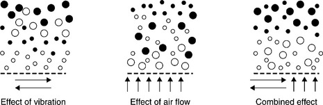
10.14 Stratification mechanisms in FGX Dry Separator. Low density coal shown as solid black particles. (Source: Based on Lu et al., 2003.)
Since their development in the 1980s, FGX separators have been widely adopted in China, with over 800 units now installed, and many are now also being used overseas. The largest current commercial unit, the 25 × 20 m FGX 48A, processes coal from 6 up to 80 mm in size at a rate of 480 t/h (FGX SepTech, n.d.). They achieve Ep values in the range 0.20–0.30 and density cut points from 1.8 to 2.2 (Honaker et al, 2007). Hence they are particularly well suited to de-stoning applications, and have even been adopted in that role in locations where water is plentiful.
10.5.4 Optical and X-ray sorting
Automated sorting devices separate particles based on their optical properties. From a bulk feed, particles need to be presented in a thin layer only one particle thick and not in contact. This is usually done by a chute or conveyor belt. A sensor is then used to determine each particle’s composition. Many different radiation wavelengths have been trialled, including visible light, X-ray and infrared. Some physical mechanism, usually an air jet, is then used to separate the product and reject particles.
This technology has developed rapidly in the last few decades with the improvement of sensor technology and computational speed. Automated sorters are one of the few dry processes that can achieve similar density cut points and separation efficiencies as water-based dense medium processes. Verboomen and Blagden (2009) report obtaining Ep values in the range 0.025–0.10 using the DRYSCAN™ laser-based sorter (Fig. 10.15) for different size ranges of coal between 10 and 75 mm with capacities of up to 200 t/h and occupying less than a 3 m diameter footprint. Von Ketelhodt (2010) reports promising results using dual energy X-ray transmission (DE-XRT) sorting coal in the 30–100 mm size range.
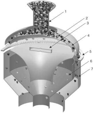
10.15 Schematic of the DRYSCANTM sorter. Feed particles (1) enter and are distributed over a conical surface (2) to form a thin layer. They are analysed by a rotating laser source (3) as they drop off the edge of the cone (4) and air jets (5) are then used to separate reject (6) from the coal (7). (Courtesy Australian Inspection Technologies Pty Ltd.)
These automated sorting technologies are restricted to coarser material, generally greater than 30 mm in size, and relatively narrow size ranges, say up to 3:1 between the top and bottom size. The requirement to present the particles as separate non-touching entities restricts the capacity of individual units. The radically different nature of these technologies from other existing processes also creates challenges for operator training and effective maintenance. However, as these technologies continue to develop and mature, they will become more cost effective. They may be particularly suited to initial de-stoning (Länger and Bickert, 2010).
10.5.5 Electrostatic and magnetic separators
Electrostatic separation of fine coal, whilst technically feasible, must be able to address potential safety risks, and the effects of variations in coal moisture content. Magnetic separation does have some potential, as coal is nonmagnetic, whereas much of the mineral matter associated with the coal is paramagnetic or even, in some cases, ferromagnetic. However, the biggest drawback to either of these technologies is the limited throughput, as the requirement to present < 6 mm particles in thin layers restricts capacity to only 2 t/h per metre of width (Länger and Bickert, 2010).
10.6 Conclusion and future trends
Growing water shortages and the continuing improvement in dry separation technologies mean that these dry processes will be adopted in a greater number of situations. However, the lower separation efficiency of dry processes, especially when applied to the finer particles, means that small and fine streams will continue to be processed using water-based methods. So we are likely to see the more frequent occurrence of hybrid plants, where the initial de-stoning and coarse particle separation steps are conducted using dry technologies, with the small and fine streams continuing to be processed using water-based methods.
In water-based plants, there is growing interest in treating material in the 0.5–4.0 mm size range, allowing the cut size for the intermediate circuit to shift from 1 mm up to say 4 mm. A suitable technology for processing this intermediate size that can perform to the existing levels of the DMCs over this size range is therefore needed.
Candidates are the fine coal dense medium cyclone, teetered bed type separator or RC. This approach will enable the use of a single DMC with diameter of 1.5 m or larger to efficiently treat a combined coarse and intermediate stream with top size over 150 mm. The reduction in the concentration of particles smaller than 4 mm in size should lead to improved medium recovery in the dense medium cyclone circuit.
Given that the capacity of screens increases at least linearly with the screen aperture size, there are significant benefits that arise from shifting the classification size towards 4 mm. The capacity of new and existing screen decks would then be increased dramatically, leading to major capital savings in the design of new plants, and in the cost of upgrading existing plants to operate at higher capacity. The classification at 4 mm in size would not have to be highly efficient as DMCs are known to separate any misplaced particles less than 4 mm in size with satisfactory efficiency.
The required rate of water addition, per tonne of feed solids, for washing the particles through the screens could therefore be reduced, resulting in higher underflow pulp densities, perhaps in excess of 20% solids. The undersize material could therefore be delivered directly to a suitable gravity separation device, eliminating the need for a bank of cyclones, and associated pumps and sumps for concentrating the undersize. This simplification in plant design would also produce energy savings.
10.7 Sources of further information and advice
For those interested in a general introduction to the field of coal preparation, the texts by Osborne (1988), Williamson and Davis (2002) and Sanders (2007) are a good start. Information on the latest developments in the field can be found in journals such as the International Journal of Coal Preparation and Utilization and Minerals Engineering, and also in the proceedings of regular coal preparation conferences such as those hosted by the Australian Coal Preparation Society (ACPS, www.acps.com.au), the Society for Mining, Metallurgy & Exploration (SME, www.smenet.org) and the International Coal Preparation Congress. The Australian Coal Association Research Program (ACARP) sponsors research on a broad range of topics of interest to the coal industry, including coal preparation. The abstracts of these reports can be viewed at www.acarp.com.au and the full reports can be purchased for a fee. The US Department of Energy (DOE) also sponsors research into coal processing that is publicly available from their information bridge website www.osti.gov/bridge/. There is also much research going on in many other coal producing and exporting countries.
10.8 References
Addison, C., Addison, F., Stanley, F., Luttrell, G., Bratton, R., Yoon, R.-H., Development of a multi-stream monitoring and control system for dense medium cyclones. R.Q., Honaker. International Coal Preparation Congress 2010 Conference Proceedings, 2010:306–312. [Littleton, SME].
Atkinson, B., Swanson, A., Swanson, A., Firth, B., O’Brien, M. Best Practice Guide to Dense Medium Cyclone Sampling and Analysis, 2007. [ACARP Report C16005.].
Atkinson, B., Swanson, A. Large Diameter DM Cyclone Operating Data, 2007. [ACARP Report C12050.].
Barbee, C.J., Luttrell, G.H., Wood, C.J., Bethell, P.J. Simulation of heavy medium cyclone performance. Minerals and Metallurgical Processing. 2005; 22:38–42.
Barbee, C.J., Wood, C.J., Luttrell, G.H., Development of a transponder-based tracer system for evaluating dense medium separation performance. SME Annual Meeting, 2008:24–27. [February 2008, Salt Lake City, UT.].
Batchelor, G.K. Sedimentaion in a dilute polydisperse system of interacting spheres. Part 1. General Theory. J. Fluid Mech.. 1982; 119:379–408.
Bethell, P.J., Luttrell, G.H., ‘Coal preparation’, in Cutler C J, Encyclopedia of Energy: Volume 1, 507–528. New York, Elsevier. 2004;, doi: 10.1016/B0-12-176480-X/00287-4.
Bicknell, J.A., Whitmore, R.L., Particle forces in fluidized bedsDrinkenburg, A.A.H., eds. Proc. Int. Symp. on Fluidization. Netherlands University Press, Amsterdam, 1967:31–37.
Boycott, A.E. Sedimentation of blood corpuscles. Nature. 1920; 104:532.
Cavanough, G.L., Holtham, P.N., Powell, T.M., D., Mathewson. Proceedings of the Twelfth Australian Coal Preparation Conference. Medium density measurement without the need for a gamma ray source, 2008:80–88. [Darling Harbour, 19–23 October, Australian Coal Preparation Society, Paper 3A].
Clarkson, C.J., Wood, C.J., P.J., Lean. Fifth Australian Coal Preparation Conference. A model of dense medium cyclone performance, 1991:65–79. [Newcastle, 13–16 May, ACPS, Paper B3].
Clarkson, C., Holtham, P., Efficiency of large diameter dense medium cyclones. Aust. Coal Rev, April 1998;(Issue 5):30.
Clarkson, C.J., Edward, D.J., Davidson, J., Lahey, A.E., B., Firth. Proceedings of the Ninth Australian Coal Preparation Conference. Analysis of large diameter cyclone plant performance, 2002:68–89. [Yeppoon, 13–17 October, Australian Coal Preparation Society, Paper B1].
Chen, Q., Yang, Y., Development of dry beneficiation of coal in China. Coal Preparation 2003; 23:3–12, doi: 10.1080/07349340302266.
Chu, K.W., Wang, B., Yu, A.B., Vince, A. CFD-DEM modelling of multiphase flow in dense medium cyclones. Powder Technology. 2009; 193:235–247.
Engelbrecht, J.A., Bosman, J., J., Smitham. Seventh Australian Coal Preparation Conference. Design criteria for an improved large diameter dense medium cyclone, 1995:108–117. [Mudgee, 9–15 September, Paper B3, Australian Coal Preparation Society.].
Fan, M., Chen, Q., Zhao, Y., Luo, Z., Guan, Y., Fundamentals of a magnetically stabilized fluidized bed for coal separation. Coal Preparation 2003; 23:47–55, doi: 10.1080/07349340302263.
FGX SepTech (n.d.). Available from www.fgxseptech.com/index.asp, Accessed 06 September 2011.
Firth, B., Holtham, P., O’Brien, M., Hu, S., Dixon, R., Burger, A., Sheridan, G. Joint Evaluation of Monitoring Instruments for Dense Medium Cyclones, 2010. [ACARP Report C17037].
Firth, B., O’Brien, M., McNally, C. Influencing Factors for Dense Medium Cyclones, 2011. [ACARP Report C18040.].
Galvin, K.P., Pratten, S.J., Nicol, S.K. Dense medium separation using a teetered bed separator. Minerals Eng.. 1999; 12:1059–1081.
Galvin, K.P., Belcher, B.D., Pratten, S.J., Callen, A.M., Lambert, M., Nguyentranlam, G. Pilot Scale Reflux Classifier for Density and Size Separations, 2002. [Grant Report, ACARP Project C10049.].
Galvin, K.P., Walton, K., Zhou, J. How to elutriate particles according to their density. Chem. Eng. Sci.. 2009; 64:2003–2010.
Galvin, K.P., Zhou, J., Walton, K. Application of closely spaced inclined channels in gravity separation of fine particles. Minerals Eng.. 2010; 23:326–338.
Galvin, K.P., Callen, A.M., Spear, S. Gravity separation of coarse particles using the reflux classifier. Minerals Eng. 2010; 23:339–349.
Honaker, R.Q., Saracoglu, M., Thompson, E., Bratton, R., Luttrell, G.H., Richardson, V., Dry coal cleaning using the FGX separator. Proceedings of the 24th Annual International Pittsburgh Coal Conference. Johannesburg, South Africa, 2007.
Hu, S., Firth, B., Vince, A., Lees, G. Prediction of dense medium cyclone performance from large size density tracer test. Minerals Eng.. 2001; 14:741–751.
Hu, S., Firth, B., B., Atkinson, S., Atkinson. Thirteenth Australian Coal Preparation Conference. Prediction of operating performance of dense medium cyclones from medium densities, 2010:154–166. [Mackay, 12–17 September, Australian Coal Preparation Society, Paper 4C].
Hyde, D.A., Williams, K.P., Morris, A.N., Yexley, P.M. The beneficiation of fine coal using the hydrosizer. Mine and Quarry. 1988; 17:50–54.
Khan, A.R., Richardson, J.F. Fluid-particle interactions and flow characteristics of fluidized beds and settling suspensions of spherical particles. Chem. Eng. Comm.. 1989; 78:111–130.
Länger, B., Bickert, G., B., Atkinson, S., Atkinson. Thirteenth Australian Coal Preparation Conference. Dry coal preparation in Australia: vision or necessity?, 2010:195–208. [Mackay, 12–17 September, Australian Coal Preparation Society, Paper 5B].
Laskovski, D., Duncan, P., Stevenson, P., Zhou, J., Galvin, K.P. Segregation of hydraulically suspended particles in inclined channels. Chem. Eng. Sci.. 2006; 61:7269–7278.
Leonard, J.W., Metallurgical and Petroleum Engineers, 4th ed. Coal Preparation. The American Institute of Mining, New York, 1979.
Lockhart, N.C. Dry beneficiation of coal. Powder Technol.. 1984; 40:17–42.
Lu, M., Yang, Y., Li, G.. Proceedings 20th International Coal Preparation Conference. The application of compound dry separation in China, 2003:81–95. [Lexington, KY].
Lundt, M., de Korte, G.J. Leeuwpan fine coal dense medium plant. J. S. African Inst. Min. Met.. 2010; 110:671–676.
Luttrell, G.H., Barbee, C.J., Bethell, P.J., Wood, C.J. Final Technical Report: Dense Medium Cyclone Operation, 2005. [Department of Energy.].
Mackinnon, W., Swanson, A., R.Q., Honaker. International Coal Preparation Congress 2010 Conference Proceedings. Strategies for washing Australian coals, 2010:9–17. [Littleton, SME].
Macpherson, S.A., Iveson, S.M., Galvin, K.P. Density based separations in the Reflux Classifier with an air–sand dense–medium and vibration. Minerals Eng.. 2010; 23:74–82.
Meyers, A.D., Sherritt, G., R.Q., Honaker. International Coal Preparation Congress 2010 Conference Proceedings. Delineation of large diameter dense medium cyclone performance, 2010:276–287. [Littleton, SME].
Mohanty, M.K., Zhang, B., Akbari, H., Hirschi, J.C., Mohanty, M.K., Zhang, B., Akbari, H., Hirschi, J.C., Mohanty, M.K., Zhang, B., Akbari, H., Hirschi, J.C. Evaluation of FGX Dry Separator for Cleaning Illinois Basin Coal, 2010. [Final Report, ICCI Project 08-1/4.1A-4.].
Moritomi, H., Iwase, T., Chiba, T. A comprehensive interpretation of solid layer inversion in liquid fluidised beds. Chem. Eng. Sci.. 1982; 37:1751–1757.
Narasimha, M., Brennan, M.S., Holtham, P.N., Napier-Munn, T.J. A comprehensive CFD model of dense medium cyclone performance. Minerals Eng. 2007; 20:414–426.
Osborne, D. Coal Preparation Technology; Vol. 1. Graham & Trotman, London, 1988.
Partition Enterprises. Available from www.partitionenterprises.com.au/index.php?option=com_content&view=article&id=17&Itemid=25, 2011. [(Accessed 14 December 2011).].
Prashant, D., Xu, Z., Szymanski, J., Gupta, R., Boddez, J., Dry cleaning of coal by a laboratory continuous air dense medium fluidized bed separator. R.Q., Honaker. International Coal Preparation Congress 2010 Conference Proceedings, 2010:608–616. [Littleton, SME].
Purdon, P., Gibson, L. Evaluation of Ultra-Dynamics Non-Nuclear Density Gauges, 2012. [ACARP Report C19043.].
Richardson, J.F., Zaki, W.N. Sedimentation and fluidisation. Trans. Inst. Chem. Eng.. 1954; 32:35–53.
Rhodes, M., 2nd ed. Introduction to Particle Technology. John Wiley & Sons, Chicester, 2008.
Sanders, G.J., 4th ed. The Principles of Coal Preparation. Australian Coal Preparation Society, Newcastle, 2007.
Sherritt, G., Meyers, A., Bennetts, A., Graham, J. Delineation of Large Diameter Dense Medium Cyclone Performance., 2010. [ACARP Report C17036.].
Sripriya, R., Dutta, A., Dhall, P.K., Narasimha, M., Kumar, V., Tiwari, B.S. An analysis of medium losses in coal washing plants. Int. J. Miner. Process.. 2006; 80:177–188.
Suasnabar, D.J., Fletcher, C.A.J., A CFD model for dense medium cyclones. Second International Conference on CFD in the Minerals and Process Industries. CSIRO, Melbourne, Australia, 1999. [6–8 December.].
Taggart, A.F. Handbook of Mineral Dressing. New York: Wiley & Sons; 1945.
Verboomen, J., Blagden, T. Benchmark for Dry Beneficiation of Coal by Laser Sorting. ACARP Report. C13052, 2009.
Vince, A., Purdon, P., Gibson, L., Hughes, T. Evaluation of Gekko IPJ Coal Separator. ACARP Report. C16042, 2007.
Vince, A. Investigation of Misplaced Material in Large Dense Medium Cyclone Sampling and Analysis. ACARP Report No.. C16005, 2008.
Vince, A., Gibson, L., Purdon, P., Hughes, T., R.Q., Honaker. International Coal Preparation Congress 2010 Conference Proceedings. Gekko IPJ coal separator value addition in coal preparation, 2010:352–361. [Littleton, SME].
Vince, A., Yu, A. Estimation of Steady State and Dynamic Dense Medium Cyclone Performance: Phase 3. ACARP Report. C16043, 2010.
Von Ketelhodt, L., R.Q., Honaker. International Coal Preparation Congress 2010 Conference Proceedings. Deshaling of coal by duel energy X-ray transmission sorting, 2010:571–580. [Littleton, SME].
Wang, B., Chu, K.W., Yu, A.B., Barnett, G.D., Barnett, P.J. Computational study of the multiphase flow and performance of dense medium cyclones: Effect of body dimensions. Minerals Eng.. 2011; 24:19–34.
Weale, W., Swanson, A., Improved design and operational data for large diameter dense medium cyclones Yeppoon, 13–17 October, Paper B2. B., Firth. Ninth Australian Coal Preparation Conference, 2002:90–106. [Australian Coal Preparation Society.].
Williamson, M.M., Davis, J.J., Cleaning coarse and small coalSwanson, A.R., eds. Advanced Coal Preparation Monograph Series, Part 8 (2nd ed.), Volume III. Australian Coal Preparation Society, 2002.
Wills, B.A., 6th ed. Mineral Processing Technology. Butterworth-Heinemann, Oxford, 1997.
Wood, C.J. A performance model for coal washing dense medium cyclones. University of Queensland, Australia, 1990. [PhD Thesis, JKMRC].
Wood, C.J., Density tracers for coal plant audits and research. SAIMM Colloquium, 2004. [Johannesburg.].
1The University of Newcastle and FLSmidth Ludowici have a Research and Development Agreement on applications involving the Reflux Classifier. The University of Newcastle owns relevant international patents, and the technology is licensed to FLSmidth Ludowici. The first author of this chapter, K.P. Galvin, is a beneficiary of the University of Newcastle’s policy on intellectual property.