
Cleaning of fine and ultrafine coal
Abstract:
Fine coal cleaning involves the use of density-based separators and circuits that utilize the unique characteristics of each unit to achieve the optimum performance. For particles smaller than 0.15 mm, froth flotation is the most effective technology, although density-based separators have shown the potential to be an adequate substitute for difficult-to-float coals.
11.1 Introduction
The cleaning of fine coal has a clear advantage over coarse coal cleaning, in that cleanability improves due to liberation as the particle size decreases. However, the separation efficiency performances of the processes used to clean fine and ultrafine coal are significantly lower than the dense medium processes typically used to treat coarse and small coal. In addition, capital and operating costs exponentially increase as the targeted lower particle size limit for recovery becomes smaller. This trend is in part due to lower throughput capacities of the cleaning units, reagent requirements, sophistication of the technologies needed to remove moisture from the final product, and the requirements of thickening and handling fine waste. The inability to achieve acceptable product moisture values often limits the ability to recover the ultrafine coal fractions.
Despite the potential to avoid such moisture issues, dry cleaning processes for fine coal have not emerged as being accepted as a commercially viable option. This has been largely due to the difficulty in achieving effective density-based separations using air as a medium with units having acceptable capacity and overall size. However, electrostatic separators relying on differences in the particle surfaces charges have been developed to commercial scale, although they have experienced limited success due to their inability to economically control humidity. Magnetic separators have also seen limited commercial success with most applications involving the treatment of pulverized coal prior to being injected into utility boilers. Generally, separation efficiencies tend to favor the use of water-based processes.
Fine and ultrafine coal typically represents about 10–20% of the plant feed, although there are reports of operations with as high as 50% of the feed being finer than 1 mm. The amount is a function of the friability of the coal, the mining technique used to extract the coal, the materials handling system employed from the mine face to the plant feed belt, and the type of crushing system used to achieve the desired particle top size. Fine coal is generally classified as the material having a particle size between 1 and 0.15 mm. A more precise definition of the top size may be the particle size selected as the bottom particle size treated in the small coal circuit. The 1 mm top size is common for fine coal circuits due to the ability of dense medium cyclones, which are the predominant small coal cleaning technology worldwide, to achieve efficient separations on 1 mm particles, and the relative ease to recover the magnetite using screens with 1 mm screen or sieve openings. Conventional density-based fine coal cleaning technologies become ineffective when treating particle sizes approaching 0.15 mm. As such, ultrafine coal cleaning circuits that generally exploit differences in surface chemistry properties, e.g., a froth flotation process, are used to upgrade particles finer than 0.15 mm.
A number of developments over the past few decades have resulted in improvements to conventional fine coal cleaning technologies and the commercialization of new processes, which have significantly improved efficiency and thus the economic viability of recovering fine coal. A list of commercially available technologies and the range of particle sizes that each typically treat is provided in Fig. 11.1. The upper size limit of the graph is 1 mm to reflect the typical top size of fine coal circuits. Spiral concentrators, water-only cyclones and fluidized-bed systems are capable of treating particle sizes as coarse as 3 mm. Compared to all the coal cleaning processes, dense medium cyclones provide the most efficient cleaning of fine coal (de Korte, 2002; Lundt and de Korte, 2010). However, the difficulty and cost associated with the overall circuit, including the magnetite recovery system, have limited the application in commercially operating fine coal circuits. Spiral concentrators are currently the most widely used technology worldwide for treating fine coal, due to their low capital cost and operational simplicity. However, fluidized-bed separators, also commonly referred to as teeter-bed or hindered-bed separators, have gained popularity when low separation density values are required to achieve product quality specifications.
Efficiency drops exponentially for the separations achieved on particles finer than 0.2 mm under natural gravity conditions. Enhanced gravity separators (EGS) have been developed that utilize traditional density-based separation principles in a mechanically-applied centrifugal field to clean coal as fine as 45 μm. However, desliming of the EGS product is needed and classification or screening systems with the capability of achieving efficient, high capacity particle size separations at around 25 μm are not available. Column flotation is the most efficient technology currently available that can selectively remove high ash content slime material from the ultrafine coal. As such, column flotation is effective in producing clean coal concentrates containing ultralow (i.e., < 3%) ash content when the ash-bearing minerals are completely liberated from the coal. Oil agglomeration processes have also demonstrated this ability but have been restrained from commercial use by the high treatment cost.
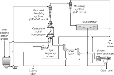
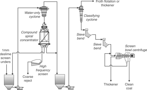
The flow sheet of a typical fine coal cleaning circuit used in coal preparation plants is shown in Fig. 11.2. The underflow stream from the deslime screen which is nominally finer than 1 mm is combined in a sump with recycle streams from sieve bends used to deslime the spiral product. The material from the fine coal sump is pump fed to a bank of raw coal classifying cyclones to achieve a particle size separation of around 0.15 mm. Classifying cyclones with a diameter of 380 mm are an industry standard for the application, but units with a diameter of 500 mm are sometimes utilized when froth flotation is included in the circuit. The larger diameter units decrease the number of cyclones required and thus reduce the negative efficiency impacts associated with feed distribution. The underflow stream from the classifying cyclone bank contains the coal with a particle size range of nominally 1 × 0.15 mm. Due to the nature of classifying cyclones, approximately 20–30% of the finest, high ash content particles (slime) in the feed report to the underflow stream due to hydraulic entrainment and thus must be removed from the clean coal product prior to dewatering.

Density-based separators such as the spiral concentrator or fluidized-bed units are used to clean the underflow stream of the classifying cyclone. As shown in Fig. 11.2, compound spiral concentrators produce three product streams: clean coal, middlings, and reject streams. The clean coal stream is deslimed and dewatered using a screening system, which is typically a two-stage sieve system. Advanced screening systems such as the Derrick Stacksizer provide improved desliming efficiencies and utilize screen medium that is less prone to wear (Brodzik, 2007). It is also common to employ clean coal classifying cyclones to assist in desliming the fine circuit product ahead of the screening units, which takes advantage of the higher throughput capacity of the cyclone units and thus reduces the number of screening units. The reject stream from the spiral concentrators is sized using a high frequency screen whereby the screen overflow is combined with the plant coarse reject material. The screen underflow stream reports to the thickener.
Froth flotation devices are typically used to clean the coal in the overflow stream of the raw coal classifying cyclone, which ideally contains particles finer than 0.15 mm. For coal being cleaned for the utility market, the recovery of coal particles finer than 45 μm typically has a negative impact on the overall clean coal product due to moisture issues unless thermal driers are available. In this case, a classifying cyclone bank containing cyclones with a diameter of 150 mm is used to deslime the raw coal classifying cyclone overflow stream prior to being fed to flotation as shown in Fig. 11.2. The flotation process treats the cyclone underflow material and produces a clean coal product that is combined with the deslimed spiral concentrator product and then dewatered in a centrifuge or high-pressure filter. For metallurgical markets, treatment of the entire raw coal classifier cyclone overflow stream by a flotation process is the most common strategy, due to the elevated market value of the coal.
There are many fine coal cleaning process alternatives as well as wide variations in the overall circuitry arrangement. The technologies and the ultimate circuit used to clean a particular coal are largely a function of the washability characteristics, the product quality specifications, and the efficiency levels and capacity of the processes at the required separation condition. In the following sections, the various fine and ultrafine coal cleaning technologies available for commercial use will be fundamentally discussed along with their typical application and operating characteristics.
11.2 Fine gravity separators
The density-based technologies used to clean fine coal utilize flowing film principles and/or differential settling velocities in a medium of water. The separation efficiencies provided by the water-only units are inferior to those achieved by the dense medium processes used on coarse coal. However, their typical efficiency levels combined with improved liberation characteristic of the fine coal provide an effective upgrading while maximizing coal recovery.
11.2.1 Spiral concentrators
In a survey of coal preparation plant practices, it was estimated that spiral concentrators cleaned about 12% of the total amount of coal processed worldwide, which is the largest among the fine coal cleaning technologies (Kempnich, 2000). The popularity among coal operators is a result of their low capital cost, light weight fiberglass construction, ease of operation due to the lack of moving parts, and the ability to resist coal from entering the tailings stream while requiring limited supervision and maintenance. Due to their light weight, two- or three-spiral units are intertwined around a single supporting shaft, which significantly improves throughput capacity per unit of floor space. Conventional spirals have 5.25 turns around the vertical shaft, whereas compound spirals, which combine two-stages of cleaning into one unit, have 7 turns.
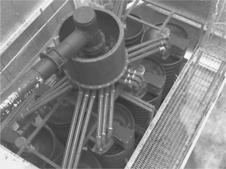
The feed mass and volumetric capacity reporting to each spiral unit, commonly referred to as a ‘start,’ is relatively low compared to the total fine coal circuit feed rate. As such, a feed distributor shown in Fig. 11.3 is required to provide equal volume splits of feed to all spiral starts. The effectiveness of the distributor to provide equal flow to all spiral starts is critical for achieving optimum separation performance from the spiral circuit.
Operating principles
Separation by density occurs as a result of primary flow and circulating secondary flow patterns, which are created as the feed slurry travels along an elongated helical trough surface that spirals downward around a central axis. The primary flow is responsible for carrying the particles in the downward direction toward the discharge point. As shown in Fig. 11.4, the secondary flow occurs along the cross-section of the trough due to greater frictional retardation in the liquid layers near the trough surface as compared to the upper layers. Light coal particles located on the inside portion of the trough are elevated upward and carried to the outer portions of the spiral by the secondary flow. The high-density, high-ash content particles tend to stay on the inside of the trough and those that are either originally located or transported to the outer region of the trough settle to the surface and report back to the inner trough area with the circulating secondary flow. Two adjustable splitters located at the discharge of the spiral separate the material along the trough into three product streams, i.e., clean coal, middlings, and tailings.
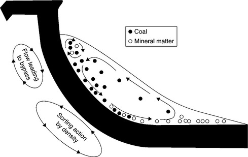
The existence of a counter-rotating flow located on the far outer portion of the trough shown in Fig. 11.4 was largely unrecognized until recently. Separation data from conventional spirals revealed that around 10% of the high-density particles in the feed reported to the clean coal stream. Recognizing this issue, Luttrell et al. (1998, 2007) conducted an extensive study that revealed the presence of the counter-rotating flow using tracers. The study found that using a circuit comprising conventional spirals in a rougher–cleaner arrangement significantly reduced the amount of high-density particle bypass to the product stream. Spiral manufacturers followed the study with the development of a slurry repulping box (Fig. 11.5), which is placed on the trough surface about 3–4 turns down the spiral. At this location, an initial amount of reject material is directed off the trough and into an inner collection channel and the remainder of the slurry is collected in the repulping box, homogenized, and then re-injected onto the spiral trough. As a result, a two-stage separation is achieved by one spiral start, commonly referred to as the compound spiral, the result being a significant improvement in separation performance with only a 30% increase in total height compared to a conventional spiral.

Fine coal spiral operating conditions and performances
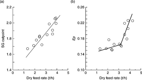
One of the advantages of coal spirals is their ability to achieve high coal recovery values when operated correctly. Regarding the clean coal product quality, the general emphasis is to achieve a specific gravity (SG) cut-point of around 1.60 to optimize overall plant performance. As a result of detailed pilot plant studies, Li et al. (1993) found that the SG cut-point achieved by a spiral concentrator is a function of the feed volumetric flow rate and the solids concentration by weight as well as the splitter position. The combination of volumetric feed rate and solids concentration represents the mass feed rate to each start, which has also been directly related to the SG cut-point value (Subasinghe and Kelly, 1991, 1992; Holland-Batt, 1994). A general relationship developed from plant data shown in Fig. 11.6a clearly indicates that any increase in the mass feed rate to a spiral significantly increases the SG cut-point. In addition, a similar trend exists for the probable error (Ep) value, which reflects a decline in separation efficiency with a rise in the feed mass flow rate (Fig. 11.6b).
Volumetric flow rate to a spiral start has a direct effect on the SG cutpoint independent of the feed mass flow rate (Li et al., 1993). For a given set of splitter positions, the SG cut-point will decrease with a corresponding drop in the volumetric feed rate. Excessively low feed rates lead to coal loss in the tailings stream. An indication that the feed volumetric flow rate is within the desired range is a liquid level that is 1.0–1.5 cm from the outer spiral lip. (Luttrell et al., 2007). A properly operating feed distributor provides equal volume flow to each of the spiral starts. However, inadequate fluid levels in the distributor or plugging of the distributor outlets causes variations in the volume flow rate reporting to each start, which results in a wide range of SG cut-points. Under this condition, the overall efficiency of the spiral circuit is reduced significantly. As such, it is recommended that operators conduct periodic checks for proper volumetric flow to each spiral start.
Based on the objective to achieve a separation approaching a 1.6 SG cut-point, the volumetric feed slurry flow rate needs to be around 7–8 m3/h with a solids concentration in the range of 25–30% by weight (Luttrell et al., 2007). The combination of volumetric flow rate and solids concentration values yield a mass flow rate range of 2.0–2.7 t/h per start.
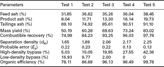
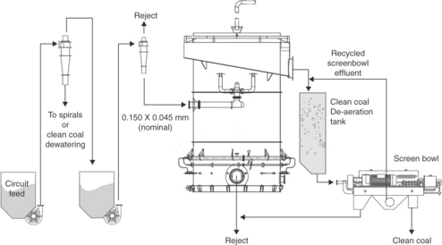
The feed mass flow rate effect on the performance of a SX7 compound spiral was evaluated at the Liberty processing plant located in West Virginia, USA (Bethell and Arnold, 2003). Feed solid concentrations of 25% and 30% by weight were tested while maintaining the volumetric flow rate at a level consistent with the other spiral starts in the plant. As shown in Table 11.1, the SG cut-point and the separation efficiency as measured by the Ep value were significantly impacted by the change in the mass flow rate reporting to the spiral with 25% feed solids, providing lower SG cut-points and improved efficiency, which is consistent with the trends in Fig. 11.6a and 11.6b.
Table 11.1
Separation performance comparison at two different mass flow rates to a SX7 compound spiral
| Performance parameter | 25% feed solids content | 30% feed solids content |
| SG50 | 1.68 | 1.85 |
| Ep | 0.155 | 0.185 |
Source: Bethell and Arnold, 2003.
Based on the favorable results achieved from the in-plant testing, the entire spiral circuit at the Liberty processing plant was replaced with compound spirals (Bethell and Arnold, 2003). A performance evaluation was performed on the conventional spiral circuit before dismantling and repeated after installation of the compound spiral circuit. The new circuit is comprised of 12 SX7 triple start compound spirals with a designed capacity of 2.3 t/h per start. The compound spiral circuit provided significantly lower clean coal ash content at a higher SG cut-point, which reflects substantially improved process efficiency. As shown in Table 11.2, the recovery of the 1.8 sink SG fraction, which contained a high amount of ash-bearing material, was reduced from 5.86% to 1.03% by the compound spiral circuit.
Table 11.2
Comparison of separation performances achieved from conventional and compound circuits at an operating processing plant.

Source: Bethell and Arnold, 2003.
Ultrafine coal spiral operating conditions and performances
The potential for achieving effective density-based separations on particles finer than 0.15 mm using spiral concentrators was first reported by Richards et al. (2000). Honaker et al. (2007) followed with a detailed study to evaluate the potential of cleaning ultrafine coal. The study involved a parametric evaluation from which the data were used to develop empirical models to describe the separation performance as a function of the feed solids concentration, feed volumetric flow rate, and splitter position. To achieve optimum performance, the mass throughput capacity was around 0.5 t/h per spiral start, which is significantly lower than the 2.3 t/h value recommended for treating the 1.0 × 0.15 mm size fraction. This finding reflects (1) the impacts of increased particle population with a reduction in particle size, and (2) the need for greater particle retention time. Similar findings were reported by Benusa and Klima (2008), although the stated impacts of feed solids and volumetric flow were less significant. The optimum volumetric feed rate was approximately 3 m3/h at a feed solids concentration of 15% by weight.
Separation performances from the treatment of 0.2 × 0.045 mm coal using a conventional coal resulted in product ash values ranging from about 8% to nearly 20% under varied operating conditions (Table 11.3). The ash value of the feed coal was greater than 30%. It is noted that the performances were achieved on material that was not deslimed and, thus, contained a significant amount of material smaller than 0.044 mm. The product ash values reflect those obtained from the 0.2 × 0.045 mm only. To achieve the lower product ash values, a substantial amount of low density material was bypassed to reject, which resulted in relatively low organic efficiency values. Likewise, a large amount of high-density, high ash value particles were bypassed to the product when targeting relatively high product ash values. The most desirable performance corresponded to a product ash value of 13%, which provided an organic efficiency of 96%.
Table 11.3
Process performance and efficiency data achieved from the cleaning of 0.21 × 0.044 mm Coalberg seam coal under varied conditions using a conventional coal spiral
The use of spiral concentrators for ultrafine coal cleaning is especially effective when sulfur reduction is a focus. Arnold and Petrunak (2006) reported on two coal processing plants in the USA using SX7 Multotec compound spiral circuits to treat nominal 0.149 × 0.044 mm coal. The ultrafine spiral circuit in a preparation plant treating Pittsburgh No. 8 seam coal achieved a total sulfur reduction from 3.44% to 0.98% while also reducing ash content by 67%. In the application involving the treatment of Illinois Basin coal, the total sulfur was reduced from 3.62% to 2.53% with a corresponding decrease in ash content from 21% to around 7%. Efficiency data from the operating ultrafine spiral circuits indicated higher SG cut-points than the 1.0 × 0.15 mm cleaning with nearly equal product qualities. Stated benefits over the use of froth flotation include lower operating costs with no chemical requirements, essentially no horsepower usage, minimal component wear, and no additional manpower needs.
11.2.2 Water-only cyclones (WOC)
The WOC is a Dutch State Mines (DSM) technology that has been used since the 1950s for cleaning coal having a particle size below 1 mm. The process remains widely popular, due to its relatively low capital cost, simple design, and the use of water as the medium. Capital cost has been estimated to be around $325 per tonne of installed capacity (Bethell and Moorhead, 2003). Disadvantages include issues related to efficiency, i.e., (i) loss of coarse coal to the reject stream, and (ii) a poorer overall efficiency as indicated by published Ep values that generally exceed 0.20. The ultimate Ep value achieved for a given coal is a function of the particle size range being treated, as the SG cut-point varies widely with particle size. As a result, the combined performance is inferior to the performance achieved for each particle size fraction. The loss of low density coal to the underflow is the reason for utilizing multiple WOCs in a rougher–scavenger circuit arrangement whereby the scavenger overflow stream is recycled back to the circuit feed. The large dilution water requirement in the scavenger feed stream is one explains why the industry prefers to use WOCs in a circuit with spiral concentrators rather than a total WOC circuit.
Operating principles
The density-based separation that occurs in a WOC is a result of differential settling in a centrifugal field under the influence of an autogenous medium. Similar to classifying cyclones, the water-only unit comprises a cylindrical section and a conical section, as shown in Fig. 11.7. The noticeable difference between a WOC and a classifying cyclone is the truncated cone, which has an angle of around 75° as compared to the 10° cone of a classifying cyclone. As a result, the solids concentration that naturally occurs in the bottom of the cone is pushed upwards into the cylindrical portion of the WOC. Since the high-density, high ash content particles move at a faster rate to the cylinder and cone walls, the high solids suspension near the bottom of the cylinder creates a heavy, autogenous (natural) medium of particles that low density, low ash content grains cannot penetrate unless they are sufficiently large in particle size. For coarse particles, the separation is generally a result of differential solid density in which the high-density particles report to the underflow stream and the low density particles to the overflow stream. As the particle size decreases, the separation becomes more influenced by particle size, which results in a decline in the density-based separation efficiency.

The vortex finder, which provides passage of the clean coal to the overflow stream, extends deep into cylindrical portion to emphasize the building of the autogenous medium and to prevent bypass of high-density ash-bearing particles into the overflow stream. The length of the vortex finder is approximately equal to the diameter of the cylindrical section and controls the SG cut-point. The underflow stream containing the high ash content particles exits through the apex or spigot, which is usually around 25% of the cyclone diameter (Schlepp and Schmidt, 1988).
Operating parameters
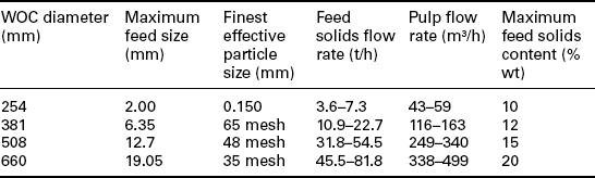
The operating conditions required to achieve optimum performance are a function of the particle size distribution of the feed coal. A list of volumetric and mass flow rates for given particle size material is provided in Table 11.4. For the treatment of nominal 1 × 0.15 mm coal, a 380 mm diameter cyclone is typically used with a recommended maximum solids concentration limit of 12% by weight. Conditions that exceed the recommended feed solid concentrations may result in bypass of high-density particles to the overflow stream, thereby increasing the ash content of the clean coal.
Table 11.4
WOC size and feed stream characteristics as a function of the feed particle size
Source: Krebs website, http://www.flsmidth.com/en-US/Products/ Product + Index/All + Products/Hydrocyclones/KREBS + Water + Only + Cyclones/Water + Only + Cyclones.
The volumetric and mass throughput capacity of the 380 mm WOC as shown in Table 11.4 is significantly lower than the typical fine coal circuit feed stream. As such, it is common that multiple WOC units are needed and thus are arranged in a bank or nest as shown in Fig. 11.8. The feed is distributed to the cyclones under pressure by pump or gravity. The recommended feed pressure for the 380 mm units is in the range of 68–103 kPa.

WOC-spiral concentrator circuit
Due to the inefficiencies of a single-stage WOC, industrial applications utilize a two-stage process with a recycle stream, which significantly improves process efficiencies. The recycle stream is also the source of significant disadvantages in that a larger number of cyclones, pumps and sumps are required and the balancing of the circuit is more complex. Furthermore, the objective of the rougher–scavenger arrangement of WOC units is to capture the coarse coal that is lost in the primary stage. However, the secondary stage has the same separation characteristics and, thus, is likely also to reject the coarse coal to the underflow stream, thereby eliminating the benefits of the circuit.
A fine coal cleaning circuit comprising WOC units as a rougher and spiral concentrators as a scavenger takes advantage of their respective desirable separation characteristics. The WOC has the ability to provide low SG cutpoints when necessary to achieve low ash or sulfur content values, but tends to lose coarse coal to the reject stream. Spiral concentrators have the ability to achieve a high recovery of coal at higher SG cut-points than the WOC. As such, using the spiral as a scavenger unit to recover coarse coal from the WOC reject stream has a clear advantage in separation performance compared with a circuit using only WOC units.
The WOC-spiral circuit with spiral middlings recycle is shown in Fig. 11.9. The WOC bank receives feed from the fine coal feed sump and produces a final clean coal product that is deslimed and dewatered by clean coal classifying cyclones and two-stage sieves or alternative screening technology. The WOC underflow stream is diluted to the appropriate feeds solids concentration and then treated in a spiral concentrator. The spiral product is combined with the WOC clean coal stream before desliming in the clean coal classifiers, while the middlings stream is recycled to the fine coal circuit feed sump. Spiral reject is the tailings stream for the fine coal circuit. This circuit is typical when a relatively high SG cut-point is sufficient to produce the desired product quality while maximizing coal recovery. However, if a lower SG cut-point is required, alterations to the circuit can be made such as eliminating the recycle of the spiral middlings stream and combining the stream with spiral tailings while changing design and operating parameters in the WOC units to achieve a low SG cut-point (i.e., < 1.60 SG).
11.9 WOC-spiral concentrator circuit with spiral middlings recycle. 11.10. Typical fluidized-bed separator.
Bethell and Moorhead (2003) conducted a very detailed study of the WOC-spiral circuit and analyzed various coal cleaning target scenarios. One of the most significant conclusions was that the ability to practically utilize the various WOC-spiral circuit arrangements is strongly a function of the recycle load. For example, consider the following recycling scenarios:
Scenario 1: Recycle of spiral middlings stream – the recycle analysis indicates that the recycle stream reaches a maximum of 7% of the raw feed. At this low level, Bethell and Moorhead concluded that there should be no constraints that limit the ability to recycle the spiral middlings stream and that the recycle load is significantly lower than the recycle load of a water-only two-stage circuit.
Scenario 2: Recycle of the spiral product and rejecting the middlings stream material to circuit tailings – under this condition, the recycle load is significant and preferentially reflects a build-up of material in the 1.0 × 0.6 mm particle size fraction. As such, recycling of the spiral clean coal stream can be achieved only when the top size of the circuit feed is 0.6 mm or smaller.
Scenario 3: Recycle of the spiral product and middlings stream – elevated recycling rates occur when the SG cut-point achieved by the WOC unit is less than 1.55. Therefore, recycling of both streams can be achieved as long as the SG cut-point of the WOC is 1.5 or greater.
Performance evaluations were performed on the WOC-spiral circuits at two operating plants by Bethell and Moorhead (2003). For Plant 1, the objective was to produce a very clean product for the metallurgical market, which required making adjustments to achieve a low SG cut-point. To achieve this objective, the spiral middlings were directed to the circuit tailings stream; thus no recycle was used. Plant 2 required a high SG cut-point to remove high-density material and ensure maximum coal recovery. In this case, the spiral middlings stream was recycled and spiral product was combined with the WOC product to form the circuit clean coal product. The separation performances for the two plants are provided in Table 11.5. In both cases, the fine coal cleaning objectives were achieved efficiently by the WOC-spiral circuit. The circuit in Plant 1 with no spiral middlings recycle provided significant ash reduction, resulting in a product ash content of around 6% while recovering nearly 90% of the combustibles. Likewise, the separation realized by the circuit in Plant 2, which recycled the spiral middlings stream, obtained a high SG cut-point of 2.1 at an organic efficiency of 99% while achieving the desired upgrading of the coal.
Table 11.5
In-plant WOC-spiral circuit performances with and without middlings recycle
| Parameter | Plant 1: No recycle | Plant 2: Middlings recycle |
| Feed ash (%) | 37.11 | 13.11 |
| Product ash (%) | 5.59 | 7.03 |
| Tailings ash (%) | 83.68 | 77.86 |
| Mass yield (%) | 59.63 | 91.43 |
| Combustible recovery (%) | 89.52 | 97.82 |
Source: Bethell and Moorhead, 2003.
11.2.3 Fluidized-bed density separators
Due in part to the focus on reducing the inefficiencies resulting from feed distribution, fluidized-bed separators have gained significant attention over the past decade for the application in fine coal cleaning. Throughput capacity is relatively high, at around 20 t/h per m2 of floor space. Low SG cutpoints and a high level of efficiency have been reported from several fine coal applications. Disadvantages include the need for close oversize control in the feed stream to prevent coal loss and the significant variation in the SG cut-point of the 1.0 × 0.15 mm particle size range.
Fluidized-bed separators are frequently used for particle density or particle size separations for which the application requires simple adjustment of the operating parameters. The units are also commonly referred to as teeter-bed or hindered-bed separators. Typically, these devices are open-top vessels through which elutriation water is injected. This teeter water is commonly distributed across the base of the cell through a network of distribution pipes or perforated plating.
Operating principles
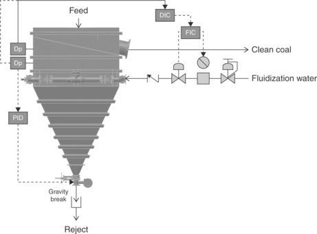
During operation, feed solids are introduced into the upper section of the separator and are influenced by teeter or fluidization water as shown in Fig. 11.10. While the smallest/lightest particles are hydraulically carried over into the collection launder, the coarser/denser particles have sufficient mass to settle against the fluidization water and create a ‘teeter bed’ of suspended particles or an autogenous medium through which particles must settle to report to the underflow stream. The small interstices within the bed create high interstitial liquid velocities that resist the penetration of the slower settling particles. As a result, intermediate small/light particles continue to accumulate in the upper section of the separator and are eventually carried over the top of the device into a collection launder. Large/heavy particles, which settle at a rate faster than the upward current of rising water, eventually pass through the fluidized bed and are discharged from one or more restricted ports through the bottom of the separator.

The separation provided by a teeter-bed separator is governed by the following:
where Ut is the hindered-settling velocity of a particle (m/s), g the acceleration due to gravity (m/s2), d the particle size (m), ρs the density of the solid particles (kg/m3), ρf the density of the fluidizing medium (kg/m3), η the apparent viscosity of the fluid (kg-m–1 s–1), 9 the volumetric concentration of solids, φmax the maximum concentration of solids obtainable for a given material, and βa function of Reynolds number (Re). By inspection of Equation [11.1], it can be determined that both the size of a particle and its density greatly influence how that particle will settle within a hindered state. As such, teeter-bed separators are frequently used in the minerals processing industry to segregate fine particles according to size, shape or density. Over a relatively narrow particle size range (i.e., approximately 3:1), the teeter-bed separator can be used to segregate coal from the associated mineral matter based on density.
Operating parameters
The main operating parameters that control the separation achieved by the fluidized-bed separator are volumetric and mass feed flow rates, fluidization water rate, and the teeter-bed height. Mass flow rate is typically in the range of 15.0–20.0 t/h/m2 depending on the particle size range of the feed and the washability characteristics. The minimum solids concentration of the feed should be 30% by weight or higher to reduce the impact on the hydraulic loading of the unit. As such, the typical classifying cyclone underflow is ideal feed for a fluidized-bed separator. The fluidization water rate controls the density of the fluidized particle bed and the amount should be approximately 15 m3/h/m2 and may change due to the particle size distribution being treated.
The teeter-bed height needs to be controlled to allow light particles to be lifted more easily into the overflow stream. If the bed is too low, light particles that are sufficiently large to allow settling above the particle bed are not able to be lifted out of the unit and thus become part of the fluidized bed of particles. A particle bed that is too high results in high-density, high ash content particles bypassing into the product stream. As shown by Fig. 11.11, the fluidized bed height is controlled using a pressure transducer to measure the bed pressure and send a signal to a control that compares the reading with the pre-set value. If the bed pressure is greater than the pre-set value, the control signals an underflow valve to open in order to release larger amounts of material into the underflow stream. When the reading is below the pre-set value, the controller maintains the underflow valve at a partial or full close position until the bed level builds to the desired level. Bed density control can be achieved by adding a second pressure transducer in a vertical alignment with the first transducer to measure differential bed pressure. This allows on-line adjustment of the SG cut-point through manipulation of the fluidization water rate using a controller.
Fluidized-bed applications
The most common application of the fluidized-bed separator is as a substitute for spiral concentrators although operators are attempting to increase the upper particle size application to unload the dense medium cyclone circuit. Treating the underflow of the raw coal classifier provides an ideal feed stream with solid concentrations in the range of 35–45% by weight. Also, in some instances operators have justified using a combination of both fluidized-bed units and spiral separators.
Mankosa et al. (1995) conducted tests using a fluidized-bed classifier as a pre-cleaner to a spiral concentrator bank for the treatment of a difficult-to-clean fine coal. The findings suggested that the fluidized-bed-spiral combination provides an efficient separation, as indicated by an Ep value of 0.07 for a 1 × 0.15 mm Illinois No. 5 coal. The SG cut-point was approximately 1.8. Studies comparing the separation performances achieved by spiral concentrators and fluidized-bed units found the fluidized-bed units to provide more efficient gravity separations for nominally 1 × 0.15 mm coal (Reed et al., 1995; Honaker, 1996). Nicol and Drummond (1997) described the efficiency of fluidized-bed units and several fine coal circuits for which application may prove to be beneficial. Based on the acceptance of the preliminary studies, a 75 t/h fluidized-bed unit was installed in an operating coal preparation plant in which the separator is being used as a cleaner unit for the spiral product (Drummond et al., 1998). This application reportedly provides SG cut-points below 1.6 and probable error (EP) values in the range of 0.10–0.15.
There are several commercial units available for application in fine coal cleaning. The Stokes Hydrosizer is one of the oldest technologies, and variants of this remain popular in coal preparation plants worldwide. Other commercial units include the Crossflow Separator, Floatex Separator, the Allflux Hydrosizer, and the recently developed Reflux Classifier.
The Crossflow Separator is a traditional fluidized-bed separator with a modified feed system that significantly reduces the negative effects of the hydraulic loading associated with the water entering in the feed slurry (Kohmuench et al., 2003). The CrossFlow utilizes a tangential, low-velocity feed entry system that introduces slurry at the top of the classifier. This approach allows water associated with the feed to travel across the top of the unit and report to the overflow launder with minimal disturbance of the separation chamber. To reduce the velocity of the feed flow, the feed stream enters a stilling well before flowing into the separation chamber. The feed then flows into the top of the device. Solids settle into the separation chamber as they travel between the feed entry point and overflow launder. The result of this feed presentation system, which eliminates excess feed water in the separation chamber, is an improvement in separation efficiency.
Laboratory test work was conducted on an eastern Australian coal sample using the Crossflow Separator. The organic efficiency for this test work approached 99%. The overall SG cut-point for the laboratory testing was 1.67. Separation efficiency for this testing was relatively high as indicated by an Ep value of 0.11.
Several full-scale units of the Crossflow Separator have been installed in operating fine coal circuits for cleaning nominal 1.0 × 0.15 mm coal. A 7.5 m2 unit was installed in a central Appalachia (USA) preparation plant to treat over 200 tph of fine coal. The separation performance achieved at full-scale are consistent with the performance demonstrated during the pilot-scale work. When optimized, the commercial unit achieved a product ash content of 9.5% at a combustible recovery of 97.5%. Another 7.5 m2 CrossFlow unit was installed in a western Kentucky preparation plant to treat Illinois Basin coal. The results shown in Table 11.6 were obtained while varying the bed level and fluidization water rate in an effort to identify the optimum conditions. Significant and consistent product ash values were achieved while maintaining combustible recovery values greater than 92%.The overall SG cut-point was 1.67, while separation efficiency was at a high level, as indicated by an Ep value of 0.10.
Table 11.6
Full-scale CrossFlow separation performances from an Illinois basin coal preparation plant (USA)
The Reflux Density Classifier is a unique fluidized-bed separator recently developed by Galvin and co-workers at the University of Newcastle (Galvin et al., 2004) in Australia. Commercial models include the RC1800, which measures 1.8 × 1.9 m2 along the cross-section and 3.5 m in height. The supplier, Ludowici, also offers a larger unit (RC2400) with a main dimension of 2.4 m and a smaller unit (RC600) with a dimension of 0.6 m. The total height of all units is the same as the RC1800 model. An enhanced Reflux separator is available for the treatment of finer particles down to a 75 μm. A photograph of an industrial installation is provided in Fig. 11.12.

A detailed test program was performed on a RC1800 model in an operating coal preparation plant in New South Wales, Australia. The unit was installed in a process stream to treat the nominal 2 × 0.25 mm material at a mass flow rate of 54 t/h. The overall SG cut-point and EP values achieved from an optimum test run were 1.70 and 0.15, respectively. The separation efficiencies achieved over a particle size range of 2 × 0.5 mm (4:1 ratio) were exceptional, as indicated by EP values equal to or less than 0.08. Below the 0.5 mm particle size, the EP value sharply increased to 0.15. Also, the SG cutpoint gradually increased from a value of 1.5SG for the coarsest size fraction to a 1.6SG value over a particle size range of about 3:1.
Development work has also resulted in an enhanced Reflux separator that can be used to treat ultrafine coal within the particle size range between 0.5 × 0.075 mm. The plates are 1 m in length and spaced 25 mm apart at 60° angle from horizontal with the same basic dimensions as the RC1800. The estimated mass throughput capacity of the unit is 30 t/h. A test program was performed in a preparation plant in the lower Hunter Valley of Australia at a modest throughput mass flux of 8.6 t/h/m2 (Walton et al., 2008). The typical performance resulted in an ash reduction of 40–18% while recovering 83% of the combustible material.
Exceptional separation performances were also realized on the ultrafine size fraction with EP values varying from 0.05 to 0.10 with particles smaller than 0.5 mm. The separation density followed the same trend as described above and increased with a decrease in particle size from about 1.6 to 2.2. Two commercial enhanced Reflux separators have been installed in New Zealand for the treatment of 0.35 × 0.075 mm coal. Development work continues at the University of Newcastle with the objective of increasing the upper size that the Reflux separator can treat to about 4 mm, thereby competing with the dense medium cyclone.
11.3 Froth flotation technologies and circuit variations
Froth flotation is widely regarded as one of the most efficient and economical methods for separating ultrafine particles. Froth flotation is a chemico-physical separation process commonly used to separate constituents based on differences in surface wettability. Since nearly all minerals exhibit some distinction in surface characteristics, froth flotation can, in theory, selectively separate any mixture of liberated particles. This theory is corroborated in the diversity and magnitude of mineral separation circuits throughout the world which incorporate flotation. Froth flotation is commonly found in plants which process copper, lead, zinc, tin, gold, silver, iron ore, silica, molybdenum, platinum group elements, rare earth elements, phosphates, fluorite clays, and fine coal (Wills and Napier-Munn, 2006).
11.3.1 Flotation technologies
Most of the industrial flotation machines used in the coal industry are mechanical, conventional cells. These machines consist of a series of agitated tanks (usually 4–8 cells) through which fine coal slurry is passed. The agitators are used to ensure that larger particles are kept in suspension and to disperse air that enters down through the rotating shaft assembly (Fig. 11.13). Air is either injected into the cell using a blower or drawn into the cell by the negative pressure created by the rotating impeller. For coal flotation, trough designs that permit open flow between cells along the bank are more common than cell-to-cell designs that are separated by individual weirs.

Some of the major manufacturers of flotation equipment include Wemco (FLSmidth), Metso, Svedala, and Outokumpu. The commercial units are very similar in basic design and function, although some slight variations exist in terms of cell geometry and impeller configuration. Machines with large specific surface areas are generally preferred for coal flotation, due to the fast flotation kinetics of coal and the large froth solids loadings. Flotation machines with individual cell volumes of up to 28 m3 are commonly used due to advantages in terms of capital, operating and maintenance costs. Some manufacturers also offer ‘tank’ machines, which consist of relatively short cylindrical tanks equipped with conventional impellers. The simplified structural design, which allows these machines to be much larger, can offer significant savings in terms of capital and power costs for some installations. Tank cells with volumes as large as 100 m3 are already in operation at coal plants in Australia.
Unlike conventional, mechanically agitated flotation machines, which tend to use relatively shallow rectangular tanks, column cells used in the coal industry are usually tall vessels with heights typically ranging from 7 to 16 m depending on the application. Unlike conventional flotation machines, columns do not use mechanical agitation and are typically characterized by an external sparging system, which injects air into the bottom of the column cell. The absence of intense agitation promotes higher degrees of selectivity and can aid in the recovery of coarse particles.
In general, feed slurry enters the column at one or more feed points located in the upper third of the column body and descends against a rising swarm of fine bubbles generated by the air sparging system (Fig. 11.14). Hydrophobic particles that collide with, and attach to, the bubbles rise to the top of the column, eventually reaching the interface between the pulp (collection zone) and the froth (cleaning zone). The location of this interface, which can be adjusted by the operator, is held constant by means of an automatic control loop that regulates a valve on the column tailings line. Varying the location of the interface will increase or decrease the height of the froth zone. The froth is transported from the froth zone into the product launder via mass action.

11.14 Typical column flotation cell with external sparging system. (Courtesy of Eriez Flotation Division.)
Methods of sparging in columns are numerous and include air lances, porous tubes, eductors, static mixers, and Cavitation-TubesTM. The air rate used in a column is selected according to the feed rate and concentrate-production requirements. This parameter typically has the largest effect on the operating point of the column with respect to the ash/yield curve. The bubbles generated by the air sparging system are sized to provide the maximum amount of bubble surface area given a constant energy input. In other words, the designs of the various sparging devices are engineered to provide the smallest size and largest number of bubbles possible.
For an equivalent volumetric capacity, the cross-sectional surface area of a column cell is much smaller than that of a conventional cell. This reduced area is beneficial for promoting froth stability and allowing deep froth beds to be formed. This is an important aspect of column flotation, as a deep froth bed facilitates froth washing for the removal of unwanted impurities from the float product. Wash water, added at the top of the column, percolates through the froth zone displacing dirty process water and non-selectively entrained particles trapped between the bubbles. In addition, froth wash water serves to stabilize and add mobility to the froth. Sufficient water must be added to ensure that all of the feed water that would otherwise normally report to the froth product is replaced with fresh or clarified water. It has been reported that less than 1% of the feed pulp and associated clays will report to the froth in a well-operated column (Luttrell et al., 1999). The ability to maintain and wash a deep froth layer is the main reason cited for the improved product grades when comparing column cells to conventional cells.
In contrast, conventional mechanical cells do not operate with deep froths. Therefore, these devices allow some portion of the ultrafine mineral slimes to be recovered with the water that reports to the froth. Consequently product quality is reduced by this non-selective hydraulic conveyance (i.e., entrainment) of gangue into the product launder. In fact, fine particles (< 0.045 mm) have a tendency to report to the froth concentrate in direct proportion to the amount of product water recovered. As such, the flotation operator is often forced to make the decision to either ‘pull hard’ on the cells to maintain yield (e.g., wet froth), or run the cells less aggressively to maintain grade (e.g., dry froth).
The primary advantage of utilizing wash water is the ability to provide a superior product grade when compared to conventional flotation processes. This capability is illustrated by the test data summarized in Fig. 11.15, which compares column flotation technology with an existing bank of conventional cells. As shown, the separation data for the column cells utilizing wash water are far superior to those obtained from the conventional flotation bank. In fact, the data for the column cells tend to fall just below the separation curve predicted by release analysis (Dell et al., 1972). A release analysis is an indication of the ultimate flotation performance and is often regarded as ‘wash-ability’ for flotation. This figure suggests that columns provide a level of performance that would be difficult to achieve even after multiple stages of cleaning by conventional machines.

11.15 Comparison of column and conventional flotation cells (Davis et al.,1995).
There are a significant number of full-scale column installations currently in commercial service around the world. The most popular brands of columns include the CPT CoalPro (Eriez), Jameson, and Microcel columns. Although the Jameson cell does not have the traditional column geometry, it is included since it typically uses wash water to improve ash rejection. Details related to the specific design features of the various column technologies are available in the literature (McKay et al., 1988; Finch and Dobby, 1990; Yoon et al., 1992; Manlapig et al., 1993; Davis et al., 1995; Rubinstein, 1995; Wyslouzil, 1997). The primary difference between the various columns used in the coal industry is the type of air sparging system employed. These include porous bubblers, static mixers, and dynamic air injectors. Details related to the features and operation of these systems have been discussed extensively in the literature (Dobby and Finch, 1986a; Xu and Finch, 1989; Huls et al., 1991; Groppo and Parekh, 1992; Yoon et al., 1992; Finch, 1995). Ideally, the spargers should produce small, uniformly sized bubbles at a desired aeration rate. Other factors, such as equipment costs, mechanical reliability, wear resistance, and serviceability also need to be carefully considered prior to selecting an industrial sparging system.
Due to economy of scale, recent trends in the coal industry have shifted away from the installation of large numbers of smaller units toward fewer, large units with diameters up to 5 m or more. Although most column installations involve the treatment of particles finer than 0.150 mm, several recent column operations have been installed to treat coarser particles, such as minus 1 mm feeds or deslimed 0.150 × 0.045 mm feeds. Additionally, a move to more economical cells in terms of energy efficiency has been realized as manufacturers focus on the generation of the required air bubble dispersions while using significantly less power than traditional approaches. One such device is the Eriez StackCell, which utilizes both pre-aeration methods in conjunction with traditional froth washing (Davis et al., 2011) to maximize efficiency with regard to both installation and operating cost.
11.3.2 Circuit variations
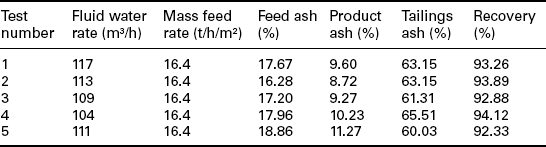
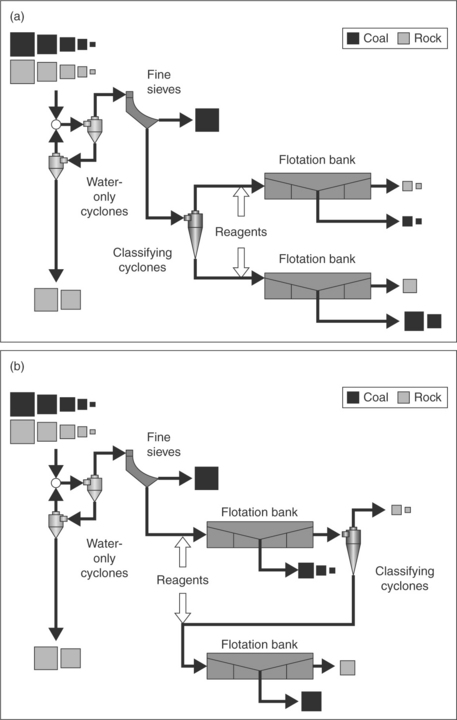
Due to the relatively low unit value of coal, flotation in the coal industry is typically performed in a single bank of cells arranged in series with no attempt to reprocess the reject or concentrate streams. In general, there are two circuits utilized for fine coal flotation. These include the traditional minus 0.150 mm ‘by-zero’ circuit and the 0.150 × 0.045 mm ‘deslime’ circuit. In the by-zero approach (Fig. 11.16), material finer than 1 mm is injected into 381 or 508 mm diameter classifying cyclones. Typically, these cyclones are configured to make a particle size cut-point of approximately 0.150 mm. In some markets, this cut-point can be up to 0.5 mm, though it is not recommended. Regardless of the cut, the cyclone overflow stream is sent directly to flotation.
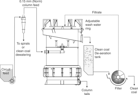
The by-zero circuit works well in plants that serve the metallurgical coal market, where ash content is the primary quality specification. However, studies have shown that a by-zero approach may not be the optimum circuitry for plants that are producing coal for the thermal market, where other quality specifications such as moisture, heat content, and sulfur are also critical (Bethell and Luttrell, 2005; Luttrell et al., 2009). These studies show that the popular ‘deslime’ circuit is better suited to achieve a separation that maximizes profitability as dictated by a typical coal-utility sales agreement. Luttrell et al. (2009) showed that product moisture plays a key role in determining the profitability of a plant producing coal for the thermal market. In fact, this study indicated that, when taking into account moisture and applying the incremental quality concept, it is necessary to discard material that is finer than 44 μm. The deslime circuit (Fig. 11.17) achieves this rejection by incorporating a secondary bank of 150 mm cyclones, which is used to further classify the flotation feed to achieve a particle size cut-point of approximately 0.045 mm. The study by Bethell and Luttrell (2005) further indicates that this approach is superior for circuits that contain clay-rich flotation feeds, where the benefit of wash water can be maximized.
The importance of minimizing entrainment is better understood when optimizing plant circuitry with respect to coal value. This optimization exercise is commonly accomplished by utilizing the incremental ash concept, which states that clean coal yield for parallel operations will be highest when all circuits are operated at the same incremental quality (Luttrell et al., 2009). In other words, all circuits in a coal preparation plant should be recovering the same quality particles, with no single circuit recovering a disproportionate amount of any unwanted component such as noncombustible mineral matter or moisture. For instance, when entrainment is not minimized, large amounts of high-ash material can be unselectively recovered. This is particularly problematic in flotation circuits that contain large amounts of ultrafine clay, which typically results in a high-ash flotation product. To compensate, other plant circuits must be operated at lower SG cut-points to achieve the desired global product specification. Based on a simple comparison between the SG of the high-ash clays and the low ash coal, approximately 3 tonnes of saleable coal is lost for every tonne of clay that is recovered into the flotation launder. As such, there is significant economic incentive to minimize entrainment and improve plant performance.
Bethell and Luttrell (2005) indicate that there are several benefits to the deslime flotation circuit that are realized due to the rejection of high surface area clays. These include a lower ash product, reduced froth moisture, an increase in flotation capacity, and an improvement in downstream froth handling. The improved froth handling is a result of two factors: a coarser float product and a significant reduction in total plant frother addition. The coarser froth product tends to be less stable and will readily collapse. The lower frother addition rate is a result of the volume split achieved in the smaller 150 mm desliming cyclones, which substantially reduces the total volume of slurry that must be processed in flotation. Given that frother is added based on total flotation volume flow, this allows high concentrations of surfactant to be realized in the flotation circuit without causing upsets elsewhere in the plant. An obvious secondary benefit is the reduction in size and cost of the flotation and downstream dewatering equipment. Overall, Bethell and Luttrell (2005) indicate that a deslime circuit may cost less than half of an equivalent by-zero circuit.
Each circuit has certain advantages. The traditional by-zero circuit will always provide the maximum product tonnes. However, the froth produced from this circuit is extremely stable and typically more difficult to handle. In addition, a dewatering scheme that can attain 100% capture (i.e., vacuum filter) should be utilized to maximize the benefit of these additional product tonnes. Unfortunately, disk filters and similar vacuum equipment do not obtain the lowest moisture values when compared to screen-bowl centrifuges. It should be noted that the traditional by-zero circuit also utilizes more frothing chemical, due to the increased volume that must be processed through the flotation circuit. Since most of this slurry volume is returned to the plant after clarification in a thickener, residual chemicals can accumulate in the process water and upset other operations in the plant.
On the other hand, the deslime circuit has continued to gain popularity due to the simplicity and ease of operation. The removal of the ultrafine material results in a higher flotation capacity and typically reduces the number and/or size of columns required for an application when compared to the by-zero circuit. In addition, the froth concentrate is coarser and provides a lower product moisture from the associated dewatering equipment, typically screen-bowl centrifuges. There are direct fine coal losses seen in the 150 mm cyclone overflow and the main screen-bowl effluent; however, these losses consist of ultrafine, high-moisture particles. More importantly, by removing the material finer than 0.045 mm, the desliming cyclones effectively reduce the volume of feed to the column circuit, which in turn diminishes any issues caused by the accumulation of residual frother.
Alternative circuit configurations may also be required in plants floating coarser coal feeds that contain large amounts of material greater than 0.250 mm, which tend to float more slowly. One option is to utilize a split-feed circuit (Fig. 11.18a), in which the coarse and fines are treated separately (Nicol and Bensley, 1988). The twin banks make it possible to independently optimize reagent dosages and equipment settings to ensure that good recoveries of coarse particles are maintained without pulling excessive slimes into the final product. Another interesting circuit modification (Fig. 11.18b) uses classifying cyclones to direct coarse particles to a second bank of scavenging cells to float coal that would otherwise be lost with rougher tailings (Firth et al., 1979). This particular configuration is well suited for retrofit applications, since it can be more readily adapted to existing circuitry.
11.3.3 Froth flotation equipment design specifications
Slurry residence time
The feed to flotation in a by-zero circuit is relatively dilute and typically ranges between 2.5% and 6.0% solids by weight. As a result, volume flows in these circuits can be quite large. Consequently, significant cell volume must be available to achieve the desired retention time to ensure adequate combustible recovery. The mean residence time can be estimated by dividing the active volume of the flotation pulp by the volumetric flow rate of tailings. It should be noted that the active volume of the cell is typically defined as the total volume of the cell minus any volume not used for particle collection such as the froth cleaning zone and the volume consumed by the rising air bubbles.
Although the detailed procedure for estimating the residence time required to achieve a given coal recovery is complex, some rule-of-thumb guidelines can be provided for typical installations. As shown in Fig. 11.19, a mean residence time of 3.5–4.0 min is often sufficient to maintain good recoveries for a four cell bank of conventional machines treating a typical minus 0.150 mm feed. The relatively short residence time required by conventional machines is due to the cell-to-cell arrangement, which minimizes the bypass of feed slurry to tailings. The required time increases when using fewer cells in series or when slower floating coals are treated (finer particles or oxidized feeds).
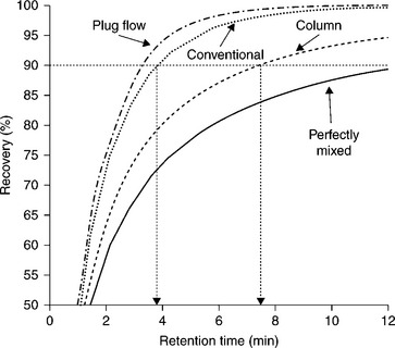
11.19 Effect of residence time on recovery for flotation systems with different mixing characteristics (flotation rate constant = 0.60 min–1).
In contrast, Fig. 11.19 also shows that column cells require more residence time to achieve the same level of coal recovery when compared to conventional cells. Due to the high flow volumes found in most coal flotation circuits, bypassing of feed can occur, which is caused by the less-than-ideal mixing found within the large-diameter and relatively short columns commonly found in coal flotation installations (Dobby and Finch, 1986b; Mankosa et al., 1992). The high degree of mixing allows some material within the cell to report to tails without being influenced by the bubble swarm produced by the sparging system. As the residence time is increased, the probability of bypass is reduced. As a consequence of this relationship, bypass is more often found in traditional by-zero circuits where the volumetric feed rates are relatively high and retention times are typically less than 4 min.
Recent studies show that arranging column cells in series helps to minimize bypass (Stanley et al., 2006). This study applied the concepts defined by Levenspiel (1972) and showed that when cells are arranged in series, the theoretical maximum combustible recovery is greater than when the cells are arranged in parallel. This concept is illustrated in Fig. 11.20, which shows the expected recovery for an efficient plug-flow system compared to both parallel and in-series column circuitry. This figure shows that, for the same residence time, float capacity, and capital expense, the expected combustible recovery can be greatly increased for any given residence time by simply rearranging the circuit flow scheme. Conversely, and given that the flotation rate constant is equal for a specific coal, the same combustible recovery can be achieved in 30% less residence time by operating column cells in-series.

11.20 Theoretical recovery as a function of active residence time for column cells (flotation rate constant = 0.60 min–1).
To obtain the needed retention time, a number of large-diameter columns may be required, which can range in height from 8.5 to 16.0 m. The ultimate height is typically based on flotation rate data generated from laboratory testing but is generally constrained by practical limits as dictated by both economic and site-specific engineering requirements. As a result, the height-to-diameter ratio for an industrial coal column generally ranges from 3:1 to as low as 2:1. As a rule-of-thumb, a column cell will typically require at least twice the residence time (twice the active volume) of a four-cell bank of conventional cells. In fact, for the case illustrated in Fig. 11.19, a column cell required a mean residence time of just over 8.0 min to obtain the same level of performance achieved using a mean residence time of just 3.7 min in a four-cell bank of conventional cells. These findings agree well with earlier suggestions by Nicol and Bensley (1988) that the pulp volume in a column must be larger than in a conventional bank.
Froth loading and stability
Operating above the maximum capacity can cause the performance of flotation cells to be poor even when adequate slurry residence time is available (Lynch et al., 1981). For example, Fig. 11.21 shows the impact of increasing volumetric feed flow rate on cell performance (Luttrell et al., 1999). The test data obtained at 2% solids correlates well with the theoretical performance curve predicted using a mixed reactor model (Levenspiel, 1972). Under this loading, coal recovery steadily decreased as feed rate increased due to a reduction in residence time. However, as the solids content was increased to 10% solids, the recovery dropped sharply and deviated substantially from the theoretical curve due to froth overloading. This problem can be particularly severe in coal flotation due to the high concentration of fast floating solids in the flotation feed and the presence of large particles in the flotation froth. Flotation columns are particularly sensitive to froth loading due to the small specific surface area (ratio of cross-sectional area to volume) for these units.

11.21 Effect of froth overloading on the recovery-residence time relationship obtained by manipulating volumetric flow rate and solids content of the feed slurry (Luttrell et al., 1999).
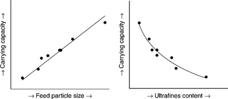
Theoretical studies indicate that loading capacity (i.e., carrying capacity) of the froth, which is normally reported in terms of the rate of dry solids floated per unit cross-sectional area, is strongly dependent on the size of particles in the froth (Sastri, 1996). Studies and extensive test work conducted by Eriez personnel also support this finding. As seen in Fig. 11.22, a direct correlation exists between capacity and both the mean size (d50) and ultrafines content of the flotation feedstock. The true loading capacity may be estimated from laboratory and pilot-scale flotation tests by conducting experiments as a function of feed solids content (Finch and Dobby, 1990). Field surveys indicate that conventional flotation machines can be operated with loading capacities of up to 1.5–2.0 t/h/m2 for finer (− 0.150 mm) feeds and 5–6 t/h/m2 or more for coarser (− 0.600 mm) feeds. Most of the full-scale columns in the coal industry operate at froth loading capacities less than 1.5 t/h/m2 for material finer than 0.150 mm and as high as 3.0 t/h/m2 for flotation feed having a top size of 0.300 mm feeds.
Froth handling is a major problem in coal flotation. Concentrates containing large amounts of ultrafine (< 0.045 mm) coal generally become excessively stable, creating serious problems related to backup in launders and downstream handling. Bethell and Luttrell (2005) demonstrated that coarser deslime froths readily collapsed, but finer froths had the tendency to remain stable for an indefinite period of time. Attempts made to overcome this problem by selecting weaker frothers or reducing frother dosage have not been successful and have generally led to lower circuit recoveries. Therefore, several circuit modifications have been adopted by the coal industry to deal with the froth stability problem. For example, froth launders need to be considerably oversized with steep slopes to reduce backup. Adequate vertical head must also be provided between the launder and downstream dewatering operations. In addition, piping and chute work must be designed such that the air can escape as the froth travels from the flotation circuit to the next unit operation.
Figure 11.23 shows how small changes in piping arrangements can result in better process performance. Shown in Fig. 11.23 is a column whose performance suffered due to the inability to move the froth product from the column launder although a large discharge nozzle (1 × 1 m) had been provided. In this example, the froth built up in the launder and overflowed when the operators increased air rates. To prevent this problem, the air rates were lowered, which resulted in less than optimum coal recovery. It was determined that the downstream discharge piping was air-locking and preventing the launders from properly draining. The piping was replaced with larger chute work that allowed the froth to flow freely and the air to escape. As a result, higher aeration rates were possible and recoveries were significantly improved.
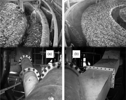
11.23 Difference in froth discharge before (a) and after (b) changes to downstream piping. (Courtesy of BMA Australia.)
Some installations have resorted to using defoaming agents or high-pressure launder sprays to deal with froth stability. However, newer column installations eliminate this problem by including large de-aeration tanks to allow time for the froth to collapse (Fig. 11.24a). Special provisions may also be required to ensure that downstream dewatering units can accept the large froth volumes. For example, standard screen-bowl centrifuges equipped with 100 mm inlets may need to be retrofitted with 200 mm or larger inlets to minimize flow restrictions. In addition, while the use of screen-bowl centrifuges provides low product moistures, there are typically fine coal losses, as a large portion of the float product finer than 0.045 mm is lost as main effluent. This material is highly hydrophobic and will typically accumulate on top of the thickener as a very stable froth layer, which increases the probability that the process water quality will become contaminated (i.e., black water).

11.24 Column with deaeration tank (a) and thickener with floating boom and sprays (b). (Courtesy of Alpha Natural Resources and Arch Coal.)
This phenomenon is more prevalent in by-zero circuits, especially when the screen-bowl screen effluent is recycled back through the flotation circuit, either directly or through convoluted plant circuitry. Reintroducing material that has already been floated to the flotation circuit can result in a circulating load of very fine and highly floatable material. As a result, the capacity of the flotation equipment can be significantly reduced, which results in losses of valuable coal. Most installations will combat this by ensuring that the screen-bowl screen effluent is routed directly back to the screen bowl so that it does not return to the flotation circuit. The accumulation of froth on the thickener, which tends to be especially problematic in by-zero circuitry, is also reduced by utilizing reverse-weirs and taller center wells, as this approach helps to limit the amount of froth that can enter into the process water supply. Froth that does form on top of the clarifier can be eliminated by employing a floating boom that is placed directly in the thickener (Fig. 11.24b) and used in conjunction with water sprays. The floating boom can be constructed out of inexpensive PVC piping, and is typically attached to the rotating rakes. The boom floats on the water interface and drags any froth around to the walkway that extends over the thickener, where it is eliminated by the sprays.
11.4 Dry fine coal separations
The cleaning of fine and ultrafine coal using air as the medium has been achieved commercially using differences in electrostatic and magnetic properties. Dry density-based separations can be achieved in the laboratory environment, but capacity and poor efficiency have prohibited commercial applications.
11.4.1 Magnetic separations
Coal particles are weakly diamagnetic, which means they are slightly pushed out from an existing magnetic field. On the other hand, most of the non-ferrous mineral matter types commonly found in coal are weakly paramagnetic, which results in a small attractive force in a magnetic field.
A patented process known as the MagMill employs an electromagnetic to achieve pre-combustion upgrading for coal having a top particle size of around 75 microns, which is typical of the coal being injected into an utility boiler feed as shown in Fig. 11.25 (Oder and Jamison, 2004, 2006). Feed coal is injected into a pulverizer in the normal manner and the material is ground to achieve the desire top size. Hot air is blown into the bottom of the pulverizer to fluidize and carry particles of the desired size out of the top of the unit. Particles that are difficult to grind, which tend to be the associated mineral matter, collect in the groove of the race mill. This material is collected and processed through the MagMill system. The electromagnetic extracts the magnetic components, while the remaining material is pneumatically transported back to the feed of the mill.
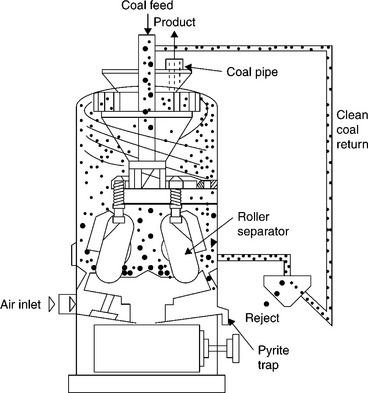
11.25 Schematic of the integration of the MagMill process with a pulverizer used to prepare utility boiler feed.
Units with a mass throughput capacity in the range of 8–22 t/h are available which can be retrofitted onto the pulverizer having throughput capacities ranging from 16 to 45 t/h. Over 70 coals covering all ranks except anthracite and a range of ash contents from 5% to 50% as well as sulfur contents from 0.5% to 5% have been evaluated (Oder, 2005). The MagMill process was found to provide significant upgrading for all coals tested. Tests conducted on a Freeport seam coal in the USA using a 1 tph MagMill reduced the ash and total sulfur contents by 40% and 47%, respectively, while recovering 91% of the energy. A 2–3 tph MagMill test unit has been constructed and installed at an utility in Vicksburg, Mississippi, USA.
11.4.2 Triboelectric separations
Triboelectrostatic separation is a dry separation process based on the surface charge that particles obtain when contacting another surface. A desirable contacting surface will result in particles with a higher work function to become negatively charged while particles with a lower work function acquire a positive charge. The work function is defined as the minimum energy that must be supplied to extract an electron from a solid. It is a measure of how tightly electrons are bound to a material. The charged particles are subsequently separated in an external electric field as a result of their different motion trajectories, which are defined by their surface charge density and charge polarity.
A schematic of a novel tribocharge separator that can be used to upgrade particles finer than 1 mm is shown in Fig. 11.26 (Tao et al., 2008). Typical tri-boelectric separators utilize air velocity to propel particles onto a charging plate/surface comprised of material (typically copper or PVC). The contact results in a surface charge polarity difference between the coal and mineral matter particles. A problem with the dependency on air velocity to provide the impact force and thus particle charging is the turbulence that is created within the separation chamber. The novel separator in Fig. 11.26 utilizes a rotor comprised of copper or other materials that provide the desired particle surface charging effect. The rotor is driven by a variable speed controller so that the impact force between the particles and the surface of the copper surface charger can be controlled by rotor speed. As a result, air velocity can be reduced to a level that maintains particle suspension and provides near laminar flow through the separation chamber. According to Jiang (2003), the particle charge density is increased by an order of magnitude using the rotary charger as compared to a standard tube charger.
11.26 Schematic of a triboelectric separator utilizing a variable speed rotor to generate surface charge (Tao et al., 2008).
Preliminary testing with several fine particle samples of coal, fly ash, and other minerals has demonstrated excellent separation performances using the novel process. For example, a clean coal of 6% ash was obtained from a − 100 micron 18% ash feed at a combustible recovery of around 85%. Tests with a − 150 micron coal that contained significant amount of middling particles produced a clean coal containing 11% ash from a 31% ash feed at a combustible recovery of 92%. In contrast, froth flotation process generated a concentrate from the same coal containing 12% ash while recovering 38% of the combustible material.
A detailed test program that investigated the benefit of upgrading South Africa coal using the novel triboelectric separator process has recently been completed. Significant upgrading was achieved on two South African coal samples (Bada et al., 2010). Ash and total sulfur rejection values of nearly 80% were obtained. The significant ash and sulfur reductions were achieved, while recovering 67% of the combustible material in the feed.
One of the problems that must be addressed when applying triboelectric separation commercially is the negative impact of surface moisture on the efficiency of particle charging and the subsequent separation process. A few units have been applied commercially to extracting unburned carbon from fly ash with limited success due to humidity/moisture issues.
11.5 Future trends
Advances in extraction technology of the past several decades have focused on increased production while minimizing costs. Extraction technology improvements have focused on increased energy density being applied at the cutting face for each tonne of coal extraction. As a result, the amount of coal finer than 1 mm reporting in the feed to the preparation plant has increased substantially. When combined with an expanded number of material transfer points and larger material storage facilities, Yanchak and Baumgardner (2012) reported that the amount of − 1 mm material tripled over the last three decades for processing plants treating Pittsburgh No. 8 seam coal in the USA. The impact on overall processing cost was significant, as indicated by the reported costs of treating the 0.6 × 0.15 mm coal and minus 0.15 mm coal being around $6 and $12 per tonne, respectively, as compared to less than $1 per tonne for dense medium circuits.
There are benefits to the processing of fine coal, including improved liberation of the mineral matter, which provides the opportunity for producing a higher quality coal product containing reduced amounts of ash and sulfur. The liberation improvement is especially significant for coal sources that originate from secondary deposits, such as those in India and South Africa. Research has shown that the cost of producing electricity from these coal sources can be reduced significantly if the ash content can be decreased to levels approaching those achieved with coals from primary deposits. Liberation by crushing coals from secondary deposits to below 1 mm may be an economically viable option that will likely be the focus of future investigations along with the development of dry cleaning technologies that can be used prior to the injection of the coal into the utility boiler.
The general increase in the generation of fines and the value of coal, especially in metallurgical markets, indicates that efforts to improve coal recovery from the fine and ultrafine size fractions will continue. Novel equipment and new approaches will be required to overcome the inherent inefficiencies found when treating this material with traditional equipment. This need helps to advance the development of new technologies and circuitry. This can be seen in the most recent plant installations where more complex circuits have been installed to take advantage of specific market requirements. In these efforts, some circuits have been optimized for producing a product for the metallurgical coal market, while other circuits within the same plant are optimized for producing coal for the thermal market (Chafin et al., 2012).
11.6 References
Arnold, B., Petrunak, D., Applications of two-stage coal spirals for fine and ultrafine coal cleaning. Proceedings of the XV International Coal Preparation Congress. China University of Mining and Technology Press, 2006:502–508.
Bada, S., Tao, D., Honaker, R., Falcon, L., Falcon, R. A study of rotary tribo-electrostatic separation of South African fine coal. International Journal of Coal Preparation and Utilization. 2010; 30(2–5):154–172.
Benusa, M., Klima, M. An evaluation of a two-stage spiral processing ultrafine bituminous coal. International Journal of Coal Preparation and Utilization. 2008; 28(4):237–260.
Bethell, P., Arnold, B. Comparing two-stage spiral to two stages of spirals for fine coal preparation. In: Honaker R., Forrest R., eds. Advances in Gravity Concentration,. Littleton: Society for Mining Metallurgy and Exploration, Inc.; 2003:107–114.
Bethell, P., Moorhead, R. Operating characteristics of water-only cyclone/spiral circuits cleaning fine coal. In: Honaker R., Forrest R., eds. Advances in Gravity Concentration,. Littleton: Society for Mining Metallurgy and Exploration, Inc.; 2003:93–106.
Bethell, P., Luttrell, G. Effects of ultrafine desliming on coal flotation circuits. In: Fuerstenau M., Jameson G., Yoon R., eds. Proceedings of the Centenary of Flotation Symposium. Australia: Brisbane; 2005:719–728.
Brodzik, P. Application of Derrick Corporation’s Stack Sizer technology in clean coal spiral product circuits. In: Arnold B., Klima M., Bethell P., eds. Designing the Coal Preparation Plants of the Future,. Littleton: Society for Mining Metallurgy and Exploration, Inc.; 2007:89–96.
Chafin, C., Bethell, P., DeHart, G., Corder, R. Maximizing fine pyrite rejection at the arch coal leer plant. In: Arnold B., Klima M., Bethell P., eds. Challenges in Fine Coal Processing, Dewatering, and Disposal,. Littleton: Society for Mining Metallurgy and Exploration, Inc.; 2012:67–78.
Davis, V., Bethell, P., Stanley, F., Luttrell, G. Plant practices in fine coal column flotation. In: Kawatra S., ed. High Efficiency Coal Preparation: An International Symposium,. Littleton, Colorado: Society for Mining Metallurgy and Exploration, Inc.; 1995:237–246.
Davis, V., Stanley, F., Kiser, M., Bratton, R., Luttrell, G., Yan, E., Kohmuench, J., Christodoulou, L. Industrial evaluation of the Stack Cell flotation technology. Coal Preparation Society of America (CPSA) Journal. 2011; 10(3):22–26.
Davis, V., Bethell, P., Stanley, F., Luttrell, G. Plant practices in fine coal column flotation. In: Kawatra S., ed. High Efficiency Coal Preparation: An International Symposium,. Littleton: Society for Mining Metallurgy and Exploration, Inc.; 1995:237–246.
De Korte, G. Dense-medium beneficiation of fine coal revisited. Journal of The South African Institute of Mining and Metallurgy. 2002; 102:393–396.
Dell, C., Bunyard, M., Rickelton, W., Young, P. Release analysis: a comparison of techniques. Transactions Insittute of Mining and Metallurgy (Sect. C). 1972; 81:787–792.
Dobby, G., Finch, J. Flotation column scale-up and modeling. CIM Bulletin. 1986; 79:89–96.
Dobby, G., Finch, J. ’Particle collection in columns – gas rate and bubble size effects. Canadian Metallurgical Quarterly. 1986; 25(1):9–13.
Drummond, R., Swanson, A., Nicol, S., Newling, P. Optimization studies on a 75 t/h teetered bed separator at Stratford coal preparation plant. In: Partridge A., Partridge I., eds. Proceedings of the XIII International Coal Preparation Congress. Australia: Brisbane; 1998:215–225.
Finch, J. Column flotation: a selected review - part IV: novel flotation devices. Minerals Engineering. 1995; 8(6):587–602.
Finch, J., Dobby, G., Column Flotation. Pergamon Press, Elmsford, New York, 1990:180.
Firth, B., Swanson, A., Nicol, S. Flotation circuits for poorly floating coals. International Journal of Mineral Processing. 1979; 5:321–334.
Galvin, K., Zhou, J., Belcher, B., Pratten, S., Callen, A., Lambert, N., Nguyentranlam, K., Investigation of the Reflux Classifier for density and size separations from pilot to full-scaleFinal Report C11008, C10049. Australian Coal Association Research Program, 2004.
Groppo, J., Parekh, B., Comparison of bubble generation devices for column flotation of fine coal from refuse’. Proceedings of the 121st Annual SME Meeting, 1992. [Phoenix, Arizona, Preprint No. 92–86.].
Holland-Batt, A. The effect of feed rate on the performance of coal spirals. Coal Preparation. 1994; 14:199–222.
Honaker, R.Q., Hindered-bed classifiers for fine coal cleaning. Proceedings, 13th International Coal Preparation Conference. Lexington, Kentucky, 1996:59–69. [30 April–2 May].
Honaker, R., Jain, M., Saracoglu, M. Ultrafine coal cleaning using spiral concentrators. Minerals Engineering. 2007; 20(14):1315–1319.
Huls, B., LaChance, C., Dobby, G. Bubble generation assessment for an industrial flotation column. Minerals Engineering. 1991; 4(1):37–42.
Jiang, X. Development and fundamental evaluation of a novel triboelectric separator. In: Ph.D. Dissertation. University of Kentucky; 2003.
Kempnich, R., Coal preparation – a world view. Proceedings of the 17th International Coal Preparation Conference, 2000:5–48. [Lexington].
Kohmuench, J., Mankosa, M., Honaker, R. Advanced in teeter-bed technology for fine coal cleaning. In: Honaker R., Forrest R., eds. Advances in Gravity Concentration,. Littleton: Society for Mining Metallurgy and Exploration, Inc.; 2003:115–124.
Levenspiel, O. Chemical Reaction Engineering. New York: Wiley; 1972.
Li, M., Wood, C., Davis, J. A study of coal washing spirals. Coal Preparation. 1993; 12:117–131.
Lundt, M., de Korte, G. Leeuwpan fine coal dense medium plant. Journal of The South African Institute of Mining and Metallurgy. 2010; 110:671–676.
Luttrell, G., Kohmuench, J., Stanley, F., Trump, G. Improving spiral performance using circuit analysis. Minerals and Metallurgical Processing. 1998; 15(4):16–21.
Luttrell, G., Kohmuench, J., Stanley, F., Davis, V., Technical and economic considerations in the design of column flotation circuits for the coal industry. Proceedings of the SME Annual Meeting and Exhibit, 1999. [Denver, Preprint No. 99–166.].
Luttrell, G., Honaker, R., Bethell, P., Stanley, F. Design of high-efficiency spiral circuits for preparation plants. In: Arnold B., Klima M., Bethell P., eds. Designing the Coal Preparation Plants of the Future,. Littleton: Society for Mining Metallurgy and Exploration, Inc.; 2007:73–88.
Luttrell, G., Keles, S., Honaker, R., Implications of constant incremental quality on the design of fine coal dewatering circuitry. Proceedings of the SME Annual Meeting & Exhibit, 2009. [Denver, Preprint No. 09–093.].
Lynch, A., Johnson, N., Manlapig, E., Thorne, C., Mineral and Coal Flotation Circuits. Elsevier Scientific Publishing, 1981:44–55.
Mankosa, M., Luttrell, G., Adel, G., Yoon, R. A study of axial mixing in column flotation. International Journal of Mineral Processing. 1992; 35:51–64.
Mankosa, M., Stanley, F., Honaker, R.Q., Combining hydraulic classification and spiral separation for improved efficiency in fine coal cleaningKawatra, S.K., eds. High Efficiency Coal Preparation. Society for Mining, Metallurgy, and Exploration, Inc, Littleton, Colorado, 1995:99–108. [Chapter 7,].
Manlapig, E., Jackson, B., Harbort, G., Jameson cell coal flotation. Proceedings of the 10th International Coal Preparation Exhibition and Conference. Lexington, Kentucky, 1993:203–219.
McKay, J., Foot, D., Shirts, M., Column flotation and bubble generation studies at the Bureau of Mines. Column Flotation’ 88. Society for Mining, Metallurgy and Exploration, Inc, Littleton, Colorado, 1988:173–186.
Nicol, S., Bensley, C., Recent developments in fine coal preparation in Australia. Industrial Practice of Fine Coal Processing. Somerset, Pennsylvania, USA, 1988:147–158.
Nicol, S.K., Drummond, R.B., A review of experience with teeter bed separators. Preprints Recent Developments in Gravity SeparatorsTechnology Review Seminar. Australian Coal Preparation Society, 1997. [May 21.].
Oder, R., The use of magnetic forces to upgrade low rank coals Lexington. Proceedings of the Upgrading Low Rank Coals Symposium, 2005:2–5. [May 2005.].
Oder, R., Jamison, R. Method and apparatus for separating material. U.S. Patent. 2004; 6:820–829.
Oder, R., Jamison, R. Method and apparatus for separating material. U.S. Patent. 2006; 7:124–968.
Reed, S., Riffey, R., Honaker, R., Mankosa, M., In-plant testing of the Floatex density separator for fine coal cleaning. Proceedings of the 12th International Coal Preparation Conference, 1995:163–174. [Lexington,].
Richards, R., MacHunter, D., Gates, P., Palmer, M. ‘Gravity separation of ultrafine minerals using spiral separators. Minerals Engineering. 2000; 13(1):65–77.
Rubinstein, J. Column Flotation: Processes, Designs and Practices. Great Britain: Gordon and Breach Publishers; 1995.
Sastri, S. Technical note: carrying capacity in flotation columns. Minerals Engineering. 1996; 9(4):465–468.
Schlepp, D., Schmidt, M. When to use water only cyclone. In: Klimpel R., Luckie P., eds. Industrial Practice of Fine Coal Processing,. Littleton: Society for Mining Metallurgy and Exploration, Inc.; 1988:81–86.
Stanley, F., King, P., Horton, S., Kennedy, D., McGough, K., Luttrell, G., Improvements in flotation column recovery using cell-to-cell circuitry Lexington. Proceedings of the 23rd International Coal Preparation Exhibition and Conference, 2006:1–4. [May 2006, 11.].
Subasinghe, G., Kelly, E. Model of a coal washing spiral. Coal Preparation. 1991; 9:1–11.
Subasinghe, G., Kelly, E. Predicting the cut specific gravity of a coal washing spiral. Minerals Engineering. 1992; 5(2):193–203.
Tao, D., Fan, M., Jiang, X., Fly ash separation using a novel rotary triboelectrostatic separator’ Beijing. Proceedings of the 24th International Minerals Processing Congress, 2008:24–28. [September 2008, 3598.].
Walton, K., Zhou, J., Galvin, K., Gravity separation of flotation feed using the enhanced reflux classifier. D., Mathewson. Proceedings of the 12th Australian Coal Preparation Conference, 2008:19–23. [October 2008, 478.].
Wills, B., Napier-Munn, T., Mineral Processing Technology: An Introduction to the Practical Aspects of Ore Treatment and Mineral Recovery, 2006. [Butterworth-Heinemann.].
Wyslouzil, H. The production of high-grade concentrates by column flotation. Skillings Mining Review. 1997; 86(37):6.
Xu, M., Finch, J. Effect of sparger surface area on bubble diameter in flotation columns. Canadian Metallurgical Quarterly. 1989; 28(1):1–6.
Yanchak, D., Baumgardner, J. Economic drivers surrounding fine coal cleaning. In: Challenges in Fine Coal Processing, Dewatering, and Disposal Symposium. Cannonsburg: Coal Preparation Society of America; 2012:23–25. [October.].
Yoon, R., Luttrell, G., Adel, G., Mankosa, M. The application of Microcel column flotation to fine coal cleaning. Coal Preparation. 1992; 10:177–188.