
12.4 z-DOMAIN ANALYSIS OF 1-D IIR DIGITAL FILTER ALGORITHM
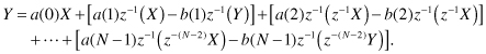
The z-domain 1-D IIR digital filter algorithm is obtained from Eq. 12.1 as
where X and Y are the z-transform of the signals x(n) and y(n), respectively, and b(0) = 0. We can think of Eq. 12.28 as a polynomial expression in the different powers of z−1. By using different polynomial evaluation techniques, the filter expression is converted to a set of recursive expressions that can be evaluated using a processor array or multiple software threads.
12.4.1 Design 3: Broadcast Inputs and Pipelined Output
Apply Horner’s’ scheme to Eq. 12.28 to obtain the recursive expression
(12.29)
![]()
The above equation can be written as
(12.31)
![]()
(12.32)
![]()
(12.33)
![]()
Based on the above iterative expression, task T(i) computes Yi in Eq. 12.30 using one multiplication and one addition:
(12.34)
![]()
The output of T(i) is buffered then forwarded to T(i − 1) and the input to T(N − 1) is initialized to 0. The above equations produce Design 1 in Fig. 12.3.
12.4.2 Design 4: Pipelined Inputs and Broadcast Output
In this design, we apply the delay operator to the input data samples to obtain delayed input data that we use to obtain our output. We start by applying our delay operators to the input samples X and Y:
(12.35)
The above equation can be converted to the iterative expressions
(12.36)
The resulting DAG is identical to that shown in Fig. 12.6.
12.4.3 Design 5: Pipelined Input and Output
A possible attractive implementation would be when both the input and output of each task are stored in a register. This implies a fully pipelined design, which is potentially the fastest design possible. Assume without loss of generality that N is even. We can write Eq. 12.28 as
(12.37)

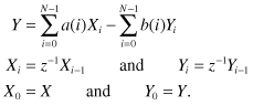
We write the above expression in the succinct form
(12.38)
![]()
We perform an iteration on the input X in the above equation:
(12.39)
![]()
(12.40)
![]()
(12.41)
![]()
(12.42)
![]()
and the output is given by
(12.43)
![]()
The above equation can be written as the iteration
(12.44)
![]()
(12.45)
![]()
(12.46)
![]()
(12.47)
![]()
Figure 12.7a shows the resulting ![]() . This is a new structure that has been reported in the literature by the author [23]. Figure 12.7b shows the details of a processor element. Note that both the input and output are pipelined between the task stages. Figure 12.7c shows the details of the first task storing the filter coefficient a(0), a(1), and b(1). Note that the output is not stored in a register.
. This is a new structure that has been reported in the literature by the author [23]. Figure 12.7b shows the details of a processor element. Note that both the input and output are pipelined between the task stages. Figure 12.7c shows the details of the first task storing the filter coefficient a(0), a(1), and b(1). Note that the output is not stored in a register.
Figure 12.7 IIR digital filter ![]() with pipelined input and output. (a) The
with pipelined input and output. (a) The ![]() . (b) Task processing details. (c) Leftmost task processing details.
. (b) Task processing details. (c) Leftmost task processing details.

12.5 PROBLEMS
12.1. Study the 1-D digital correlation operation using the z-transform technique.
12.2. Study the 2-D digital correlation operation using the z-transform technique.
12.3. Study the three-dimensional digital correlation operation using the z-transform technique.
12.4. Study the three-dimensional finite impulse response (FIR) filter using the z-transform technique.
12.5. Study the three-dimensional IIR filter using the z-transform technique.