13.3 2-D RECURSIVE FILTERS
A first-quadrant 2-D recursive filter can be represented by the equation
(13.1)
![]()
where X ≡ X (z1, z2), Y ≡ Y (z1, z2), and b(0, 0) = 0. The term ![]() represents one time step delay along a line. This delay could be implemented as memory address locators for use by the software threads or it could be implemented as actual hardware buffer for use by the software systolic array processing elements. The term
represents one time step delay along a line. This delay could be implemented as memory address locators for use by the software threads or it could be implemented as actual hardware buffer for use by the software systolic array processing elements. The term ![]() represents one sample delay along a column. For progressive raster-scanned images, this is equivalent to W time-step delays where W is the image width. The above equation can also be written in a hierarchical way as
represents one sample delay along a column. For progressive raster-scanned images, this is equivalent to W time-step delays where W is the image width. The above equation can also be written in a hierarchical way as
where the terms F(k2) and G(k2) are two one-dimensional (1-D) infinite impulse response (IIR) filter operators given by
(13.3)
![]()
(13.4)
![]()
From Eq. 13.2, it can be seen that a 2-D recursive filter can be treated as a combination of 1-D recursive filters. In the following sections, we derive different hierarchical 2-D recursive structures in terms of 1-D recursive structures.
13.3.1 2-D IIR Design 1: Broadcast X and Y Inputs and Pipelined Output
In this design, we broadcast the X and Y inputs to each 1-D filter section and pipeline their outputs to obtain the 2-D filter output. Using Horner’s rule on Eq. 13.2 in the form
(13.5)
![]()
the above Equation can be written in iterative form as
(13.6)
![]()
(13.7)
![]()
(13.8)
![]()
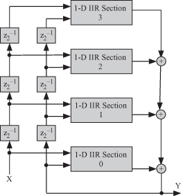
Using the results of Chapter 9, we obtain the directed acyclic graph (DAG) shown in Fig. 13.3. This design was previously developed by the author’s group in References 23 and 87. The DAG could be implemented by multithreads in software or by using systolic arrays in hardware.
Figure 13.3 DAG of a 2-D recursive filter using Design 1 for a filter window height of h = 4.

Line wraparound can be eliminated by clearing all the storage elements within the 1-D filters. This should be done after the reception of the last pixel of a given line and before the reception of the first pixel of the next line by any 1-D filter structure.
Frame wraparound can be eliminated by clearing all the storage elements within the tasks of each 1-D filter as well as all the z−1 elements between adjacent 1-D filters. This should be done after the reception of the last pixel in the last line of a given frame and before the reception of the first pixel of the following frame.
13.3.2 2-D IIR Design 2: Pipelined X and Y Inputs and Broadcast Output
Equation 13.2 is modified by associating the z−1 delay operators with the input samples. In effect, we are introducing the delays to the input signals X and Y.
(13.9)
![]()
We develop the iterative equations for the input signals as
(13.10)
![]()
(13.11)
![]()
(13.12)
![]()
(13.13)
![]()
Finally, we have the filter output given by
(13.14)
![]()
The resulting DAG is shown in Fig. 13.4. This DAG can be implemented using software multithreading or hardware systolic arrays. The systolic array of the 2-D recursive structure is similar to the one reported in References 23, 87, and 88. Line and frame wraparound can be eliminated by using the approach described in the previous section.
Figure 13.4 DAG of a 2-D recursive filter using Design 2 for a filter window height of h = 4.