19
Materials and Structures
19.1 Overview
Although aerodynamic considerations dominate the concept finalisation of a new aircraft, structures and their material selection are an integral part of conceptual design Phase I of the project to generate the aircraft's geometric shape, bearing in mind the need to minimise weight and cost of production without sacrificing structural integrity and operate safely. The underlying workload of structural engineers is stressful, bridging the gap between aerodynamicists and production planners to make the product right the first time (see the Six‐Sigma approach to design – Chapter 20).
The essence of this chapter is to consider how the aircraft is to be constructed. That is, what materials should be used and how can they be assembled together to make the aircraft. This is very important because, even at this early stage in the design process, material and manufacturing considerations can significantly affect cost and weight, leading to a reconsideration of the initial concept. The core objective is to select material that gives superior strength‐to‐weight ratio at an affordable cost. Many decisions at this point can lock in cost and weight that is difficult to recover later in the design process.
This chapter covers:
- Section 19.2: Introduction to Structures and Materials for Design
- Section 19.3: Function of Structure
- Section 19.4: Basic Definitions – Structures
- Section 19.5: From Structure to Material
- Section 19.6: Basic Definitions – Materials
- Section 19.7: Important Considerations for Design
- Section 19.8: Materials General Considerations
- Section 19.9: Metals
- Section 19.10: Wood and Fabric
- Section 19.11: Composites
- Section 19.12: Structural Considerations
- Section 19.13: Rules of Thumb and Concept Checks
It is important to note that this is not a structural design or stress analysis book, so this chapter aims only to give pointers to key aspects, and direct readers to the right places to continue with the detailed design of the structure. Exposing the topics to the readers is an essential obligation.
19.2 Introduction
In the early days of aviation there was really no choice but to use an all wood construction or with fabric cover to wrap over wooden airframe serving as aerodynamic surface. It was effective as there are centuries of experience and knowledge of wood types, their properties and manufacturability. At that time, the available metals were relatively heavy and the light ones were soft and corrosive, making wood the preferred choice. But the properties of wood have limitations with it being anisotropic and without enough resistance to impact. Moreover, as a natural material there is significant variability, and quality control is also a major issue. Today, wood is no longer used except in the home‐built aircraft category, primarily because wood is the easiest material to work with.
During the 1920s, the combination of progress in engine and aerodynamic technologies allowed aircraft speeds to exceed 200 mph. The corresponding structural loads demanded better materials. Technology changed in the 1930s when Durener Metallwerke, Germany, introduced duralumin, an alloy of aluminium with its higher strength‐to‐weight ratio, improved anti‐corrosion properties and with isotropic properties. It followed rapidly with more variety of alloys with specific manufacturability, damage tolerance, crack propagation and anti‐corrosive properties in the form of clad‐sheets, rolled bars, ingots and so on. The introduction of metal also brought a new dimension in manufacturing philosophy. This progress in structures, aerodynamics and engine power paved the way for substantial gains in speed, altitude and manoeuvre performance. These improvements were seen, pre‐eminently, in the Second World War designs such as the Supermarine Spitfire, the North American P‐51, the Focke Wolfe 190, the Mitsubishi Jeero‐Sen and so on. The Spitfire was perhaps the finest examples of these advances coming together in a highly innovative machine.
It was not then until the emergence of duralumin, now known as a 2000 series aluminium alloy, that wood had a worthy metallic competitor. Even then, it took the demands of war and mass production to tip the balance in favour of metal. But with materials science continually advancing, aluminium alloys have continued to improve and today's high end alloys have exceptional performance, far beyond those early days. The yield strength of 7075‐T6 aluminium alloy is 67% greater than 2011‐T6. As mentioned before, wood is no longer used except in home‐built aircraft category, and only there primarily because wood is an easy material to work with and is accessible and cheap.
The last three decades have seen the appearance of non‐metals, for example, fibreglass/epoxy, Kevlar/epoxy, graphite/epoxy and so on, in progressively increasing usage. These composite materials and are typically laid in layers of fabric and resin. Composites have better strength‐to‐weight ratios compared to aluminium alloys, but they have anisotropic properties. Since they are laid in moulds during fabrication of parts, difficult curvy 3D shapes can be produced with relative ease. But the quality of composite aircraft components is yet to reach the uniform high standards of metals. The immediate future will see yet more variety of composite material with metal embedded to get the best of both worlds. The Airbus 380, the Airbus 350 and the Boeing 787 are fine examples of how extensively composite material is used. Composite materials and their technology are evolving at a fast rate and the future will see greater variety of composite material with better properties and capabilities at a lower cost. The percentage use of composite material in aircraft will increase further.
The first use of composites was in secondary and tertiary structures where loads are low and failure will not result in catastrophe. But this is no longer the case with composites now extensively used in primary structures. Figure 19.1 gives the composite material usage in the Boeing767 (early 1980s) aircraft [1, 2]. As composite technology progresses, more and more composites are appearing in aircraft, particularly primary load bearing structures.

Figure 19.1 Composite material usage in B767.
Source: Courtesy of Michael Niu.
Table 19.1 compares the extent of increase of composite from an older B747 (1960s) to the relatively newer design of the B777 (1990s). The latest B787 has considerably higher percentage of composite usage at 50%.
Table 19.1 Percentage mass of types of material used in the aircraft structure.
| Material | Boeing747 | Boeing777 | Boeing787 |
| Aluminium alloys | 81 | 70 | 20 |
| Steel alloys | 13 | 11 | 10 |
| Titanium alloys | 4 | 7 | 15 |
| Composite (various types) | 1 | 11 | 50 |
| The rest | 1 | 1 | 5 |
Composite materials are becoming incorporated in increasing percentages by weight. There are few small aircraft made of all‐composite material but their FAR 23/25 certification procedure is more cumbersome than that of metal construction. The early all‐composite aircraft had to struggle to obtain flight‐worthy certification due to not having sufficient data to substantiate performance claims. Military certification standards for aircraft structure are different. Their anisotropic properties make composites difficult to analyse and design with, however, they provide the opportunity to tailor the material and create an optimised structure. Recent advances in simulation and design methods makes this achievable. The future is likely to see them used to optimise weight and strength to a much greater extent. A great example of this highly sophisticated structure is the Eurofighter Typhoon, which has a tailored aeroelastic wing. The wing is design such that in flight, under load, it adopts the most aerodynamic shape it can.
The newer military aircraft designs also use expensive exotic material (e.g. aluminium‐lithium alloy, boron alloys etc.) that are yet to prove their cost effectiveness in commercial aircraft. More than half of the Eurofighter's structural mass is made of various types of composite materials. A fifth of the Eurofighter's structural mass is made of Al‐Li alloy.
All vehicles that have to defy gravity must necessarily be weight conscious, forcing designers to choose lighter materials, or more precisely, those materials that give a better strength‐to‐weight ratio. Also implied are the questions of cost of raw material, cost of fabrication and their stability during usage. This section is devoted to making the reader aware that choosing the appropriate material is an involved topic and is an integral part of the study during the conceptual design phase. Aircraft weight and cost are affected by the choice of material and hence the aircraft performance and economy. The success and failure of a new aircraft design depends considerably on the choice of appropriate materials, especially when the number of available varieties is increasing. A choice made at this stage of the design process can embed unavoidable costs for the whole programme that may be impossible to recover at a later stage.
Although not within the scope of this book, it is interesting to note that with the advent and rapid progress made in 3D printing technologies, specific types of materials can be designed and developed to fabricate specific types of components, currently as smaller machine parts rather than larger aircraft structures.
19.3 Function of Structure – Loading
Before considering the definitions, it is worth recapping on what a structure is and the relevant function in aircraft.
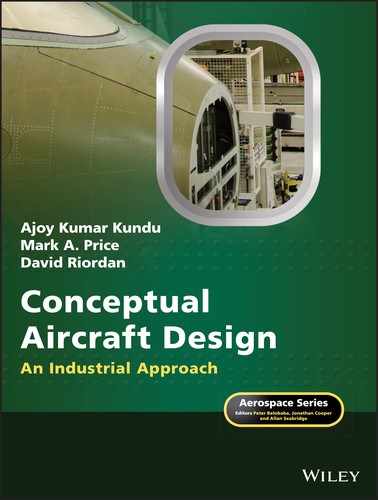
The fundamental load pattern is of two types, (i) axial load normal to the surface of a structure member (can be tensile or compressive) and (ii) shear load applied tangentially along the surface of a structure member. Figure 19.2 depicts the loading types on a rectangular cross‐section prismatic bar. Note that shear stress comes with its complementary stress [3–6].
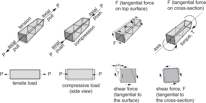
Figure 19.2 Load types on rectangular prismatic bar.
Typically, a combination of all types of loads are subjected on a structure composed of many members. Bending of a beam is a good example, as shown later in Figure 19.13. The nature of loading on aircraft components are described in a simplistic manner in the following subsections (for details, see Refs [1, 3–6]).
19.3.1 Wing
The main function of the wing is to provide the lift needed to keep the aircraft airborne. Lift is a pressure force that acts over the surface of the wing, and if the resultant total force is sufficient the aircraft flies aloft. Structurally, the wing acts like a long beam, with the upward lift force being balanced, usually in the middle, by the fuselage and main payload. This is a self‐equilibrating system, as there is no ground reaction or supports in that sense. Structurally, therefore, the wing transmits these external forces through the material structure to achieve equilibrium (Figure 19.3).
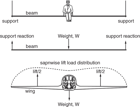
Figure 19.3 Conceptualising the aircraft wing as a beam. Structurally the system is like a playground swing, with the upward force provided by air loads (lift) rather than the ropes on the swing.
Of course, depending on the role of the aircraft, and the resulting configuration, the wing can also be required to transmit forces from wing mounted engines, undercarriage, fuel, hydraulic systems and so on. Although this makes for a more complex external loading picture the wing itself still acts like a beam a transmits the forces through the material.
19.3.2 Empennage/Tail
The empennage generates control forces for manoeuvring the aircraft. The individual elements of the empennage can be considered as wings in terms of the forces they transmit and carry within themselves. However, they also therefore transmit such forces through the adjacent structures, for example the fuselage. These forces can be very significant and can cause the structural designers difficulty in ensuring the integrity of the airframe.
19.3.3 Fuselage
In the main category of civil aircraft, the primary function of the fuselage is to provide the space and location for payload and passengers. It must hold them and keep them safe and warm. Conceptually, the weight loading is similar to the wing. In this case the distribution is for the weight of the passengers, assumed to be evenly spread over the fuselage floor (Figure 19.4). Thus far, the fuselage is also like a beam, with a uniformly distributed load over its length, supported by the lift force of the wings, acting usually in the centre of the beam. In addition, the fuselage experiences bending moments from the kinetics of the lifting surfaces.
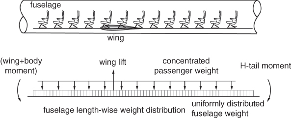
Figure 19.4 Like a beam, the fuselage with the passengers and payload provide the distributed load supported by the wing lift.
The fuselage, however, has an additional need where the aircraft flies in the stratosphere and that is to resist pressure. To keep passengers safe, aircraft are pressurised, normally to a minimum pressure equivalent to an altitude of 7000 ft. This additional pressure load provides many challenges for the structural designer, and has been the cause of major catastrophes such as the Comet disasters.
19.3.4 Undercarriage
While the aircraft is on the ground, the entire weight is transmitted through the undercarriage to the ground. In this case they act like stocky legs supporting the great weight of the aircraft. However, when the aircraft is landing, the shock loads of striking the ground are absorbed the undercarriage and subsequently transmitted through the wing or fuselage structure to which they are attached. Chapter 9 gives a fuller description of undercarriage design and the corresponding loading scenarios. Undercarriages are therefore not as beam‐like as the main airframe elements.
19.3.5 Torsion
In addition to normal load pattern as briefly described before, aircraft components get subjected to torsional load; in simple terms, they get twisted in manoeuvres, asymmetric aerodynamic loadings and so on.
Twisting along the axis of a body occurs as a result of applied torque that produces shear force on the cross‐sectional area normal to the axis of the body. Twist causes deformation and becomes significant along a long body, for example, fuselage, wing and so on, as shown in Figure 19.5.
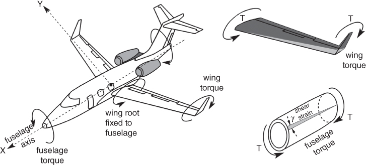
Figure 19.5 Torsional load on an aircraft.
19.4 Basic Definitions – Structures
As with any design problem it is important to have an understanding of the key parameters and definitions relevant to the problem in hand. Such basics are critical as the decisions made at any point in a shared collaborative venture should be equally understood by all team members. For example, the concept of stiffness applies to both material and the overall structure but is different for each. Material stiffness is a fundamental property of the material and so can only be changed by choosing a new material. The stiffness of the structure, however, depends on both the material and its shape. Therefore, structural stiffness can be significantly improved by modifying shape without needing to change the material. The designer needs always then to be clear which aspect is being considered and what the likely outcomes can be. As will be seen in this chapter, a change in structural stiffness can be effected by small or local design changes in a cost‐effective manner, but a change in material, say from metal to composite, can significantly impact the entire design and the manufacturing systems. In this section key basic definitions and their relevance to design are given.
19.4.1 Structure
A structure is simply the assemblage of material components that transmits and resists the applied loads to keep the aerodynamic shape, keep the passengers safe and comfortable and ensure that the aircraft can fulfil its function over its life.
19.4.2 Load
The load is the force exerted on a surface or body. In the case of the whole aircraft, these are normally categorised as air or ground loads. As the aircraft is a dynamic system it encounters many loading scenarios during its operational life, from dynamic loads arising from manoeuvres to impact loads at landing, and inertial loads from releasing stores. In the context of structures, the definitions of various kinds of loads given Chapter 17 is recast here.
19.4.3 Limit Load
The limit load for an aircraft is the maximum load it is expected encounter once in its operational life.
19.4.4 Proof Load
The proof load is the maximum load the aircraft must withstand without detrimental distortion. Under proof loading conditions, the airframe must not distort permanently more than the specified proof strain (0.1 or 0.2%). This is particularly critical for structures such as flap tracks where any permanent distortion (plastic deformation) would impair functionality. Proof load is defined as:
The proof factor is a factor of safety applied to allow for uncertainty in specifying the limit load. In civil aviation, as regulations are more conservative in defining loads, the proof factor is normally taken as 1, but in military aircraft it is usually taken as 1.125.
19.4.5 Ultimate Load
The ultimate load is the maximum load the aircraft can resist without failure. Ultimate load is defined as:
The ultimate factor is a factor of safety applied to account for uncertainties in a range of aspects, such as the variation of material properties, the degradation of material properties over time, uncertainty in analysis and key assumptions and uncertainty in flight operations (e.g. flying outside the allowable manoeuvre envelope). The ultimate factor is normally taken as 1.5 for all aircraft types.
19.4.6 Structural Stiffness
Structural stiffness is the measure of how much the structure deflects under a load. It is defined as the slope of the load deflection curve. Structural stiffness has several variants referring to the type of load and deflection, for example, bending stiffness or torsional stiffness. The structure itself may be made from elements of many materials. The relation between stiffness, K, load, P, and deflection, δ, is given here.
19.5 From Structure to Material
These key concepts and definitions thus far relate to the structure as a whole, or at least a large element of structure, such as the wing. At this point, in the design process the designer should at least be aware of these key loads. For example, they should know the total wing load resulting from say a pull‐out manoeuvre from a dive, as being an extreme load case. There are a number of structural failure modes that are critical such as wing divergence and control reversal that need to be considered at this level.
However, it should now be becoming clear that in designing the airframe the understanding of loads applied to the aircraft now must be considered in the context of the local structural elements and material itself. Clearly, the ultimate load for the whole wing is dependent on the load carrying capacity of the material, which requires conversion to stress and strain that are the material characteristics used in estimating failure. Loads therefore need to be converted into stresses ( f or s) and compared with the allowable proof or ultimate stress of the material to determine whether the design is acceptable. This task has become a major challenge in modern aircraft design. The reason is that different global conditions, for example, pull‐out versus landing, will produce different maximum stresses in different local parts of the structure. While the designer cannot at this point know all the details they must be aware of the material characteristics that are important and how these relate to design choices. This is particularly true of stiffness that can affect the configuration choice. Figure 19.6 shows a typical stress–strain curve for an aluminium alloy. A number of key definitions are based around this.
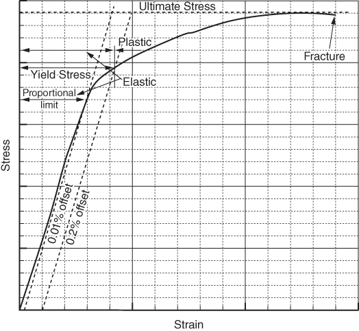
Figure 19.6 Basic stress–strain curve for an aluminium alloy.
The definitions here are couched in language relevant for the designer to understand in the context of making design decisions. For a fuller understanding and precise definitions it is necessary to refer to specialist structural design books [4–6]. But this simple overview is necessary to understand the dynamics of making decisions in material selection. Many of the properties mentioned bear inverse relationships to one another and trade‐offs are necessary, either with the material or the structural shape. These considerations are discussed in the next section.
19.6 Basic Definitions – Materials
Given next are the essential definitions associated with aircraft structural design considerations.
19.6.1 Stress
Section 19.3 mentioned that there are fundamentally two types forces (loads) to be considered in setting up stress equations. The two of loads are given here:
- Normal force, pull or push, acting perpendicular to surface.
- Shear force acting tangential to the surface.
To keep illustration simple, the small amount of dilation on deformation taking place under the normal force application, as shown in Figure 19.2, is not shown in Figure 19.7 (details can be found in the references given). The stress types are as follows.
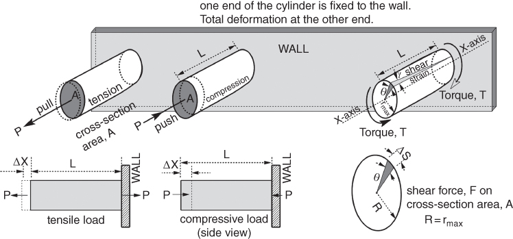
Figure 19.7 Basic stress and strain.
The definition of stress is to normalise of load applied on unit area that indicates the intensity of a force on a material (Figure 19.7).
- Normal stress, σ, is the total applied normal force, P, divided by the area, A, over which it acts.
19.2It can be a tensile stress or compressive stress, depending on whether it is pull or push and cane be identified with a subscript.

- Shear stress, τ, is the total tangential force applied, F, divided by the area, A, over which it acts.
19.3

The concept of shear stress on thin surface, for example, edges of aircraft metal/composite sheets can be expressed as shear stress per unit length termed as ‘shear flow’ (not dealt with here).
19.6.2 Strain
Strain is the non‐dimensionalised deformation of a material under stress and the two types are as follows.
- Normal strain, ε, is the ratio of the extension or contraction, x, (or stretch/shrink) of the material under load to its original length, L. It is denoted:
19.4

- Shear strain, γ, is the angular deformation under tangential force applied (details can be found in the references given).
19.5where Δx is the transverse displacement, that is, the angle between the sides of the original shape and deformed shape (Figure 19.7).

In case of torque, the twist angle, θ, produces circumferential displacement ‘dS’ on account of the applied torque straining the sold circular by the angle, γ, over the length, L.
Then dS = θR = γL where, R = rmax
or
19.6.3 Hooke's Law
The fundamental property of stress–strain relationship within the linear range of application, is shown in Figure 19.6. The stress–strain relationship obeys Hooke's Law, which states that within the linear range the ratio of stress by strain (stress/strain) is constant for both the normal and tangential loads.
The two types of stresses and strains related to stiffness are briefly described next.
- Under normal load, the material stretches or contracts depending on whether it is pull or push. It is a fundamental property of the material obeying Hooke's Law is called the Elastic Modulus (E) or the Young's Modulus, named in honour of Thomas Young. It is defined as the slope of the stress–strain curve (Figure 19.6).
19.7


- Under tangential load, the material deforms as shown in Figures 19.2 and 19.7. Its fundamental property obeying Hooke's Law is called the Modulus of Rigidity (G). It is defined as follows.


19.7 Material Properties
The choice material depends on its properties for the role it is required to perform. Given in the following are the different material properties the designers have to consider.
19.7.1 Stiffness
Material stiffness is the measure of how much the material deforms. It is measured from a material's fundamental property of stress–strain relationship within the linear range of application, as shown in Figure 19.6.
19.7.2 Yield Stress
Yield Stress is the stress level in the material that will cause permanent deformation. It is normally defined where the resulting plastic strain is 0.1 or 0.2%. This stress level is often called the 0.1% proof stress.
19.7.3 Fracture Toughness
Fracture Toughness is the stress intensity at which a crack in the material will grow rapidly until failure. It is a measure of the material's ability to resist cracks.
19.7.4 Ductility
Ductility is the ability of a material to deform plastically without fracturing. That is how much the material can be stretched after yielding.
19.7.5 Durability
Durability in the context of aircraft is the ability of the component to perform its function over its life. In aircraft design this is usually in reference to the number of flight hours or load cycles that the component can continue to function over. Cracks exist in materials naturally due to flaws in the material structure and these can grow slowly under loading. As the crack lengthens the local stress increases, eventually reaching the fracture toughness level for the material and resulting in complete failure.
19.8 Considerations with Respect to Design
Armed with the basic definitions, this paragraph discusses about how these material properties are taken into account in the design. When a reader first begins to design real structures or products, the question is usually posed very simply in terms of finding a material that is strong enough to carry the stresses or loads. However, in a real design problem it is more complicated, as the practicalities of making the structure come into play. In the context of an aircraft design a prime driver is the weight of the aircraft, and therefore the material must be used as effectively and efficiently as possible. Significant efficiency can be gained by careful shaping of the material components and the overall structural configuration. This leads directly into considerations of the cost of the structure, which clearly now depends on how material is shaped and assembled as well as the simple cost per unit weight. To determine the cost, therefore, it is necessary to consider the manufacturing process. The challenge in this is that many of these factors have conflicting requirements and what benefits the design in one sense can be detrimental in another. Trade‐offs are necessary to achieve a compromise. So real design begins!
There are four main elements then to consider in this: the properties of the material itself, the structural configuration, the manufacturing process and finally the cost.
19.8.1 Material Selection
Material properties are the main drivers to make the choice to select a suitable aircraft component under the nature of the applied load on it. Over the years of development, engineers moved from the natural material, for example, wood to a large variety of man‐made alloys and composite materials made from natural materials; each type has different properties to suit specific applications in a selective manner to fabricate aircraft components. Some general materials of interest are given in Table 19.2 (Young's Modulus, E, GigaPascals) and Table 19.3 (density, mega grams m−3), see Ref. [7]. Brief introductory considerations are given in this section on material selection in aircraft design. Readers are suggested to refer to Refs [4, 5, 7–10] for detailed study.
Table 19.2 Material Young's Modulus, E (GPa).
| E (GPa) | ||
| Metals | ||
| Ferrous | Cast iron | 165–180 |
| High carbon steels | 200–215 | |
| Medium carbon steels | 200–216 | |
| Low carbon steels | 200–215 | |
| Low alloy steels | 201–217 | |
| Stainless steels | 189–210 | |
| Non‐ferrous | Aluminium alloys | 68–82 |
| Copper alloys | 112–148 | |
| Lead alloys | 12.5–15 | |
| Magnesium alloys | 42–47 | |
| Nickel alloys | 190–220 | |
| Titanium alloys | 90–120 | |
| Zinc alloys | 68–95 | |
| Ceramics | ||
| Glasses | Borosilicate glass | 61–64 |
| Glass ceramic | 64–110 | |
| Silica glass | 68–74 | |
| Soda‐lime glass | 68–72 | |
| Porous | Brick | 10–50 |
| Concrete, typical | 25–38 | |
| Stone | 69–21 | |
| Technical | Alumina | 215–413 |
| Aluminium nitride | 302–348 | |
| Boron carbide | 400–472 | |
| Silicon | 140–155 | |
| Silicon carbide | 300–460 | |
| Silicon nitride | 280–310 | |
| Tungsten carbide | 600–720 | |
| Composites | ||
| Metal | Aluminium/silicon carbide | 81–100 |
| Polymer | CFRP | 69–150 |
| CFRP | 15–28 | |
| Natural | ||
| Bamboo | 15–20 | |
| Cork | 0.013–0.05 | |
| Leather | 0.1–0.5 | |
| Wood, typical (longitudinal) | 6–20 | |
| Wood, typical (transverse) | 0.5–3 | |
| Polymers | ||
| Elastomer | Butile Rubber | 0.001–0.002 |
| EVA | 0.01–0.04 | |
| Isoprene (IR) | 0.0014–0.004 | |
| Natural rubber (NR) | 0.0015–0.0025 | |
| Neoprene (CR) | 0.0007–0.002 | |
| Polyurethane elastomers (elPU) | 0.002–0.003 | |
| Silicone elastomers | 0.005–0.02 | |
| Thermoplastic | ABS | 1.1–2.9 |
| Cellulose polymers (CA) | 1.6–2 | |
| Ionomer (I) | 0.2–0.424 | |
| Nylons (PA) | 2.62–3.2 | |
| Polycarbonate (PC) | 2–2.44 | |
| PEEK | 3.5–4.2 | |
| Polyethylene (PE) | 0.621–0.896 | |
| PET | 2.76–4.14 | |
| Acrylic (PMMA) | 2.24–3.8 | |
| Acetal (POM) | 2.5–5 | |
| Polypropylene (PP) | 0.896–1.55 | |
| Polystyrene (PS) | 2.28–3.34 | |
| Polyurethane thermoplastics (tpPU) | 1.31–2.07 | |
| PVC | 2.14–4.14 | |
| Teflon (PTFE) | 0.4–0.552 | |
| Thermoset | Epoxies | 2.35–3.075 |
| Phenolics | 2.76–4.83 | |
| Polyester | 2.07–4.41 | |
| Polymer foams | ||
| Flexible polymer foam (VLD) | 0.0003–0.001 | |
| Flexible polymer foam (LD) | 0.001–0.003 | |
| Flexible polymer foam (MD) | 0.004–0.012 | |
| Rigid polymer foam (LD) | 0.023–0.08 | |
| Rigid polymer foam (MD) | 0.08–0.2 | |
| Rigid polymer foam (HD) | 0.2–0.48 | |
Note: VLS = very low density, LD = low density, MD = medium density.
Table 19.3 Material density (Mg m−3).
| ρ (Mg m−3) | ||
| Metals | ||
| Ferrous | Cast irons | 7.05–7.25 |
| High carbon steels | 7.8–7.9 | |
| Medium carbon steels | 7.8–7.9 | |
| Low carbon steels | 7.8–7.9 | |
| Low alloy steels | 7.8–7.9 | |
| Stainless steels | 7.6–8.1 | |
| Non‐ferrous | Aluminium alloys | 2.5–2.9 |
| Copper alloys | 8.93–8.94 | |
| Lead alloys | 10–11.4 | |
| Magnesium alloys | 1.74–1.95 | |
| Nickel alloys | 8.83–8.95 | |
| Titanium alloys | 4.4–4.8 | |
| Zinc alloys | 4.95–7 | |
| Ceramics | ||
| Glasses | Borosilicate glass | 2.2–2.3 |
| Glass ceramic | 2.2–2.8 | |
| Silica glass | 2.17–2.22 | |
| Soda‐lime glass | 2.44–2.49 | |
| Porous | Brick | 1.9–2.1 |
| Concrete, typical | 2.2–2.6 | |
| Stone | 2.5–3 | |
| Technical | Alumina | 3.5–3.98 |
| Aluminium nitride | 3.26–3.33 | |
| Boron carbide | 2.35–2.55 | |
| Silicon | 2.3–2.35 | |
| Silicon carbide | 3–3.21 | |
| Silicon nitride | 3–3.29 | |
| Tungsten carbide | 15.3–15.9 | |
| Composites | ||
| Metal | Aluminium/silicon carbide | 2.66–2.9 |
| Polymer | CFRP | 1.5–1.6 |
| CFRP | 1.75–1.97 | |
| Natural | ||
| Bamboo | 0.6–0.8 | |
| Cork | 0.12–0.24 | |
| Leather | 0.81–1.05 | |
| Wood, typical (longitudinal) | 0.6–0.8 | |
| Wood, typical (transverse) | 0.6–0.8 | |
| Polymers | ||
| Elastomer | Butile rubber | 0.9–0.92 |
| EVA | 0.945–0.955 | |
| Isoprene (IR) | 0.93–0.94 | |
| Natural rubber (NR) | 0.92–0.93 | |
| Neoprene (CR) | 1.23–1.25 | |
| Polyurethane elastomers (elPU) | 1.02–1.25 | |
| Silicone elastomers | 1.3–1.8 | |
| Thermoplastic | ABS | 1.01–1.21 |
| Cellulose polymers (CA) | 0.98–1.3 | |
| Ionomer (I) | 0.93–0.96 | |
| Nylons (PA) | 1.12–1.14 | |
| Polycarbonate (PC) | 1.14–1.21 | |
| PEEK | 1.3–1.32 | |
| Polyethylene (PE) | 0.939–0.96 | |
| PET | 1.29–1.4 | |
| Acrylic (PMMA) | 1.16–1.22 | |
| Acetal (POM) | 1.39–1.43 | |
| Polypropylene (PP) | 0.89–0.91 | |
| Polystyrene (PS) | 1.04–1.05 | |
| Polyurethane thermoplastics (tpPU) | 1.12–1.24 | |
| PVC | 1.3–1.58 | |
| Teflon (PTFE) | 2.14–2.2 | |
| Thermoset | Epoxies | 1.11–1.4 |
| Phenolics | 1.24–1.32 | |
| Polyester | 1.04–1.4 | |
| Polymer Foams | ||
| Flexible polymer foam (VLD) | 0.016–0.035 | |
| Flexible polymer foam (LD) | 0.038–0.07 | |
| Flexible polymer foam (MD) | 0.07–0.115 | |
| Rigid polymer foam (LD) | 0.036–0.07 | |
| Rigid polymer foam (MD) | 0.078–0.165 | |
| Rigid polymer foam (HD) | 0.17–0.47 | |
If the maximum stress level required for the design is around 500 MPa, then steel, aluminium alloy, titanium alloy and carbon‐fibre reinforced plastics (CFRP) are all possibilities. The strengths of these materials are compared in a bar chart as shown in Figure 19.8.
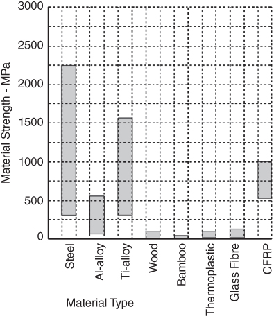
Figure 19.8 Material strength.
A quick study of the tables and figure show that, while steel is much stronger than aluminium, it is much heavier. The lightest steel is about 2.5 times denser than the heaviest aluminium alloy. This suggests that the same structure can be made much lighter if aluminium is used. In fact, based on average values the strength‐to‐weight ratio of these two materials is pretty comparable, meaning that other factors are really needed to help. There is of course a major caveat here in that there is a huge variation in properties for specific material compositions. A further complication in material properties is the inverse relationship between ultimate strength and toughness. As materials are made stronger, they have a tendency to be more brittle and have a relatively lower fracture toughness. Thus, if durability is a concern then the material chosen is may have a lower ultimate strength. Therefore, the aircraft designers need to know other material other material properties, for example, their strength, fracture toughness, costs and so on. So, any comparison like these must be made really on the exact material being considered. Many engineers make mistakes by assuming average properties when the material they have to hand is quite different. That said, the average values here are useful to make the point.
Because of these contradictory indicators a variety of metrics have been used to aid in material selection. The most common of these are the ratios of strength‐to‐weight (specific strength) and stiffness to weight (specific stiffness). Other useful measures are modulus to strength and toughness to strength. The best tools for aiding this are the graphs (Figure 19.9) developed by Ashby [8, 9] as part of a materials selection tool suite.


Figure 19.9 Material Properties [8, 9]. (a) Young's Modulus versus density. (b) Young's Modulus versus strength. (c) Strength versus density. (d) Fracture toughness versus strength.
Since cost is not a material property, it is dealt with separately in the next section. For materials with similar properties, cost varies from manufacture to manufacturer. A good example is that of building construction steel with similar specifications, the unit price is considerably lower in the Far East as compared to the prices in the West.
Another important consideration for material selection is the manufacturability of the component. This is dealt with briefly in Section 19.8.1.
19.8.2 Ashby Scatter Plots
Professor Martin Ashby of Cambridge University systematically classified and grouped materials within the class and their associated properties of interest in a series of scatter plots. The applicable ones for this book are given in Figure 19.9. These are (i) Young's Modulus versus density, (ii) Young's Modulus versus strength, (iii) strength versus density and (iv) fracture toughness versus strength and so on, can be found in Refs [8, 9]. In general, engineers like to have material of high strength, high stiffness, high toughness and low weight.
The advantages of Ashby plots are that an overview of material properties can be visualised in few graphs to make a quick comparison of the relative merits to make a decision. These graphs are useful in giving potential material choices and can provide alternatives that were perhaps not originally at the forefront of the designer's mind.
19.8.3 Material Cost Considerations
Of the manufacturing considerations in material choice, the cost of making the structure from the chosen material is critical. Again, an exotic material may provide excellent physical properties but may require new specialist equipment to machine or fabricate. It may be further complicated by being available only from a single supplier or small number of suppliers. A sole supplier can be in a powerful position and significantly affect the final cost of the aircraft.
Another factor, even with more common materials, is the effect of the world markets. Aluminium, for example, is traded in global stock markets and the price can vary widely over time. This is also true for some of the minor additives to make aluminium alloys. Again, it is crucial to know the exact grade of material to have confidence in cost, otherwise the designer must be aware of the risk.
Fundamentally, most companies have estimates for the cost of material for a given weight and use these at design stage. The company will have corporate knowledge of the additional costs of manufacture using materials with which it is familiar. It is where the designer strays into uncharted waters that risk becomes an issue. This was certainly the case for many manufacturers in building the latest generation of composite aircraft where in many cases a completely new factory was built for the manufacturing programme. These are huge risks and while at the design stage this seems far away, some consideration is always helpful, as the risk can then be taken with some confidence.
Compromise on material properties is required on account of economic factors to remain competitive in the market without compromising aircraft safety but possibly on performance, mainly arising from substitution with a heavier material. An Ashby scatter plot of material cost is given in Figure 19.10.
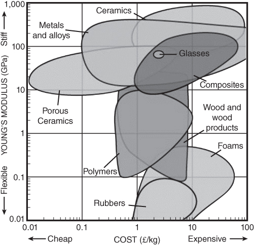
Figure 19.10 Materials cost [8, 9].
A more exacting cost of some relevant material, in terms of US$/kg, is given in Figure 19.11 in bar chart form to facilitate relative cost comparison. The comparison allows compromises to be made, if required. It is to note that the material cost varies according to global markets. Therefore, accuracy of the two figures cannot be guaranteed.
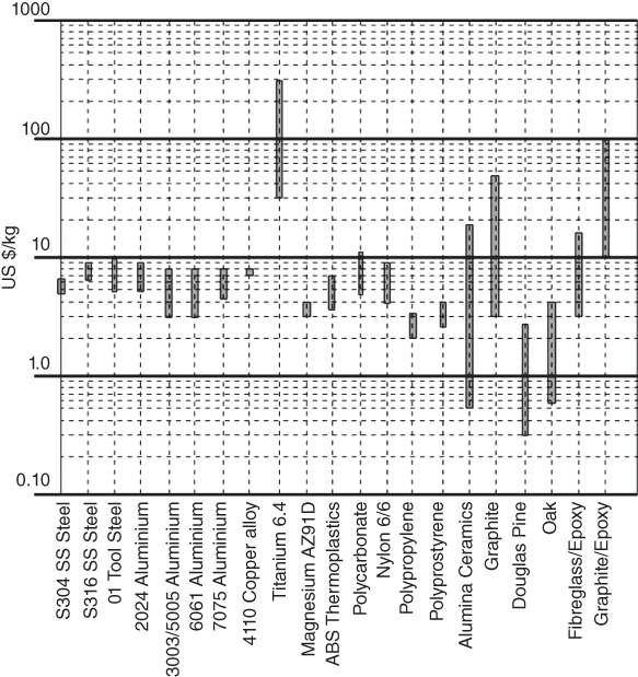
Figure 19.11 Materials cost in bar chart form.
19.8.4 Manufacture
While the detailed manufacturing programme is not yet on the horizon for the designer, at this point it is important that some heed is paid to it here. When selecting a material it is very tempting to refer to the kind of diagrams shown here or to use other look up tables available from many accessible resources to garner a range of possible materials. It is a common sight for students, and even experienced engineers when under pressure, to make a decision because a material with the appropriate properties has been identified. However, the many physical characteristics of materials also affect the manufacturing processes. Some, such as titanium and CFRP are very difficult to machine, some are very difficult to bond and some materials when together react and corrode. There are an additional and simple questions for any company: Is the material readily available and is the supply is in sufficient quantity for the project to completion? Are there appropriate manufacturing tools and systems in place to handle the material? These apparently mundane considerations can cause the designer to rethink and perhaps reshape the design so that a more accessible and cost‐effective material can be used.
An addition to the older example of Boeing767 given in Figure 19.1, is an example of a current example of the Airbus380 in Figure 19.12. It shows component‐wise material selection.
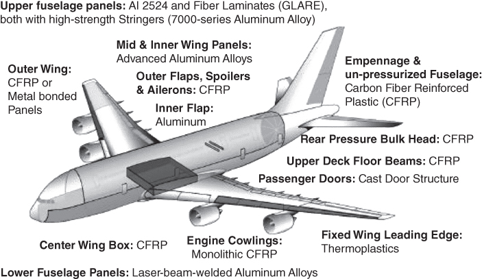
Figure 19.12 Materials selection – A380. Courtesy Airbus [11].
19.8.5 Integrated Decisions
The preceding sections have indicated four key considerations in material choice. There will always be others in a full design programme, but these four reain dominant. The last and most important consideration is that these aspects are integrated. The decision on the material choice should be based on a consideration of all four aspects: material properties, shape/configuration, manufacture and cost. It is here that the trade‐offs begin and choices are exercised such as accepting some weight gain for a cost saving, accepting higher cost for a reduction in weight or shaping the material to keep the stresses low so that a common and well understood material can be used.
19.8.6 Design Exercise
All the information given in Section 19.8 prove useful for the design exercise given here. As an exercise, consider a cantilever beam from above. By using any available resources for material properties and costs, try to enumerate a number of cross‐sectional shapes that will keep the cost of each design of the beam within a 10% margin.
As a further exercise, try to design the beam to be half the original weight, but still within 10% cost of the original. If that is too easy, then try half again and so on. Be imaginative with the cross‐sections. You can, for example, use hollow cross‐sections.
19.9 Structural Configuration
The next consideration for material choice is the shape of the component or configuration of the structure. This is important because in terms of material choice it is the stress level that matters rather than simply the load level. The stress level determines whether failure occurs, and it depends on the geometry of the component as well as the material properties.
Section 19.3 describes the types of loading the main aircraft components have to withstand. The dominant types are bending and torsion dealt with in this section.
19.9.1 Bending
For example, in Figure 19.13 a simple cantilever beam with a rectangular cross‐section under bending is shown with one end fixed and one end free. It is a simplistic representation of a wing, the free end is the tip and fixed end attached to fuselage. The maximum stress in the cantilever beam like wing spar is at the root joining the fuselage. The beam transverse cross‐section has a width of ‘b’ and depth of ‘2d’ and the neutral axis passes through the centroid at middle of the rectangular beam cross‐section; ‘y’ is the distance from the neutral axis.
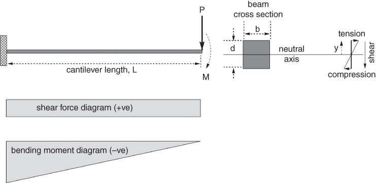
Figure 19.13 Showing cantilever beam and bending stress.
In the Figure 19.13, without any axial stress, the cantilever beam of length, L, is in pure bending under the vertical load, P, at the free end. This gives the maximum bending moment, M, at the fixed end expressed as.
The shear force is constant along its length. The distribution of shear force and bending moment along the cantilever beam is shown in Figure 19.13.
The loading condition will deflect the beam in to a shallow uniform curvature causing tension above the neutral axis and an equal amount of compression below it. The opposite forces above and below the neutral axis act as resistive forces from pure bending.
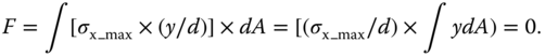
The tension makes the upper half stretch and vice versa at the bottom half on account of compression. Therefore, the cross‐section has stress distributed in linear variation from ‘0’ at the neutral axis to maximum value at the top and bottom level. The total force, F, equates to zero, top half and bottom have equal and opposite magnitudes. This expressed mathematically as follows.
Let at any elemental area dA of the beam transverse cross‐section at a distance ‘y’ from the neutral axis experiences stress, σx = σx_max × (y/d) with linear variation.
Then the elemental force, dF, on an elemental area dA of the beam transverse cross‐section is as follows.
where σx_max and ‘d’ have constant values.
Integrating over the cross‐section area,
Elemental moment, dM on account of elemental force is
Integrating moment,
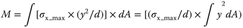
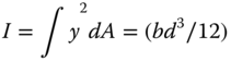
The term ∫y2dA) is the area moment of inertia, I, of about the neutral axis.
Equation 19.9 takes the final form M = (σx_max/d) × I.or
The tension makes the upper half to stretch and vice versa at the bottom half on account of compression. Consider the strain due elongation to be εx along its axis. The loading condition will deflect the beam in to shallow curvature of radius R. It can be shown [1–3] that for small deflection the following relation holds.
The distortion of the transverse cross‐section on account of tension and compression is negligibly small and is ignored here. Then applying the elastic property 19.4 in terms of Young's Modulus, E, the following can be written.
Using Eq. 19.11, at any distance y from the neutral axis, this becomes as follows:
where y = σxd/σx_max.
From Eq. 19.6, Eq. 19.12 can be written as follows
this is known as elastic flexure formula
Noting that the rectangular shaped area moment of inertia of about the neutral axis is as follows.
Then for rectangular cross‐section cantilever beam, Eq. 19.12 becomes:
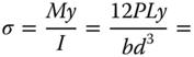
The maximum stress is at y = d/2, that makes
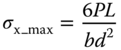
The equation indicates that the stress in the beam is inversely proportional to the depth of the beam. The longer the ‘d’ (beam depth) is, the lesser is the maximum stress, σx_max. If space is available, then for the beam cross‐section area, a deeper beam is preferred. The example given next demonstrates this.
In Figure 19.14, if b1 is set to be 0.8b, then for the same cross‐sectional area, d1 becomes 1.25d with a net reduction in stress of 20%. In a real design, if such changes are possible then lighter or cheaper materials may be used, or the section is reduced to reduce weight. It is possible to make multiple gains sometimes, by reducing the area and using a lighter material at the same time.
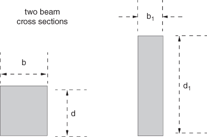
Figure 19.14 Showing two cross‐sections.
This now provides more freedom in material selection. If the stress is very high, then being able to reduce it may bring other materials into play that can offer benefits in terms of weight or cost or both. For example, reducing the maximum stress from 600 MPa to 300 MPa brings aluminium alloy into competition with titanium, carbon fibre and steel.
Although this example is simple, it is very relevant for the selection of material for an aircraft fuselage or wing. In most design cases a single wing is idealised as a cantilever beam that, although it has a more complicated cross‐section, still behaves very much like a beam. It is possible therefore to get very quick estimates of the order of magnitude of stresses in a wing to inform the initial selection of materials.
19.9.2 Torsion
Following on with the idealisation of the wing as a beam it becomes clear that torsional loads arise naturally since the elastic centre and the centre of lift are not coincident (Figure 19.15). Torsion is particularly important because twist of the wing directly influences the angle incidence and hence the lift. So, in addition to the stresses the angle of twist is a key response that needs to be known.
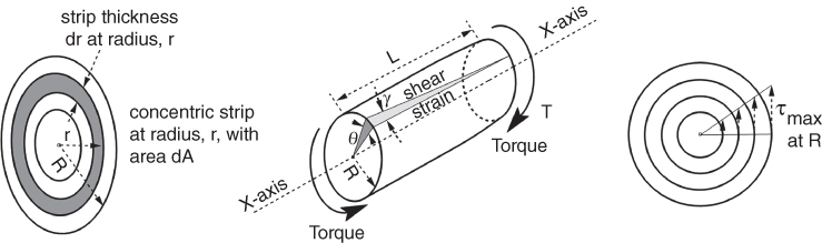
Figure 19.15 Torque on cylindrical solid shaft.
When torque is applied to a circular bar, in this case a solid cylindrical shaft, the following assumptions are taken to derive the torque equations.
- No distortion takes place on the cross‐section perpendicular to the cylinder's axis.
- Shear strain varies linear from 0 at the centre to γmax at the peripheral surface.
- Valid only in the linear range of stress–strain relation obeying Hooke's law, that is, (τ/γ) = constant = G.
This implies that shear stress,
linearly varying from 0 at the centre to τmax at the peripheral surface.
Therefore, force, F, on the cross‐sectional area, A, is given by

where, dA is the thin concentric cross‐sectional strip at radius, r.
Torque,
Hence,
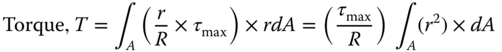
where
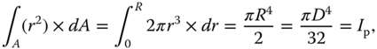
the polar moment of inertia.
For a given tube, τmax and D = 2R are constants.
On substituting, the torque Eq. 19.18 can be written as

Normally, applied torque, T, can be measured and is known, thus τmax can computed.
For a solid circular cylinder,
Airframe structures are largely thin‐walled tubes and hence this basic theory is modified to produce expressions and relationships that are more appropriate for the structural designer. In the case of hollow circular sections:
For thick tubes,
where B is the internal radius of the tube.
For thin tubes of a thickness, t, the stress variation within the thin cross‐section section is small and can be approximated by taking the average value at Rave_thin tube. This gives
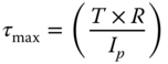
As aerofoil shapes are complex this theory has been extended significantly as a general theory of thin‐walled tubes, as shown next. Although the treatment is extensive, there are two key equations of use to the wing designer, which can be used to find the skin thickness and the wing twist. Before developing these equations, there are a couple of useful points to note. Firstly, in simple bending, all forces act through the neutral axis, also known as the elastic axis. In symmetric sections, this causes bending about the two main beam axes, but in unsymmetrical sections it also causes twist. The twist is around a point in the section called the shear centre, which is defined as the point in the section through which a shear force will cause no twist. The distance between the shear centre and the elastic centre is a critical design parameter for the structure and should be minimised if possible. Since the centre of lift is typically not through the shear centre of the wing section it means that wings always have a torsional load to deal with. A fuller treatment of these concepts is beyond the scope of this book, but these are useful key points to bear in mind in the structural design of the wing.
The neutral axis passes through the centroid of the area and the equations here are developed assuming that the torque acts along this axis. The underlying assumption in this is that the torsional load is independent from the bending load. This highly idealised assumption is conservative but perfectly suited to this conceptual stage of design to obtain initial estimates of stress and skin thickness.
Figure 19.16 shows a non‐circular uniform cross‐section tube with a constant thickness, t. It is subjected to torsion, T, about a longitudinal axis passing through its shear centre. The torque, T, produces shear stress, τ, at the tube cross‐section, as shown on the elemental circumference length, ds that associates with its complementary stress along its longitudinal direction as shown in the figure.
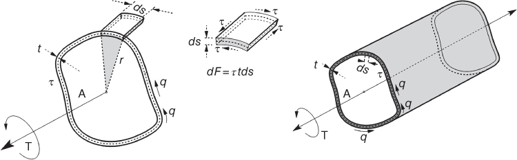
Figure 19.16 Non‐circular thin tube.
Then the elemental force dF on the elemental cross‐section of length ds can be written as follows.
This is often written in terms of the shear per unit thickness, which is called the shear flow, q, written as:
Force equilibrium gives that force per unit length along the circumference is constant. That means, for the torque loading the shear flow, q, is also constant along the circumference. This is true for non‐uniform thickness along the circumference, that is, if thickness, t, reduces then stress, τ, increases and vice versa.
Then torque, T, can be obtained by integrating the whole circumference.

where r is mean radius at ds.
The integral, ∮rds gives twice the cross‐sectional area at its mean radius r.
Therefore,

this is known as the Bredt–Batho formula.
The Bredt–Batho formula is directly useful for estimating the skin thickness needed for a given material choice. The shear stress at any point of the thin tube cross‐section (can be non‐uniform thickness) can be computed by.
The angle of twist, θ, arising from the applied torque can be obtained by the following expression (not derived).
where G is the modulus of rigidity.
References [4–6] may be consulted for its derivation as well for non‐circular cross‐section.
19.9.3 Buckling
Buckling is an unstable behaviour, a deformation that can take place on account of axial/in‐plane compressive load applied to slender column, thin plate, shell structures and so on. Characteristically, buckling shows large lateral deformation compared to axial deformation. This occurs if there is local misaligned (eccentric) loading and/or imperfections in the material.
Within the elastic limits of the material, such deformation is tolerated as deformation recovers to normality as soon as load is withdrawn. In flight, many aircraft exhibit skin buckling on wing/fuselage surfaces under flight load, loosely described as ‘tin canning’ or ‘wrinkling’. Buckling is not desirable, but if well designed, buckling accommodates flight load variation. Stiffeners/ribs are used to keep buckling deformation within acceptable limits. Modern high performance aircraft have integrally milled skins with low level of buckling.
Only the metal structure buckling characteristics are discussed briefly here. Non‐metals also exhibit bucking. Readers may refer to [1, 12] for detailed study. A brief overview is summarised here.
- Structural components under axial/in‐plane compression loads are susceptible to buckling – unstable out‐of‐plane deflection when the applied compression stress reaches a certain level, known as critical buckling stress.
- Depending on the structural geometry and material properties, the compressive stress at which a structure will buckle can be well below that of the material compressive yield stress.
- When defining the allowable compressive design stress, buckling stress must also be considered alongside the material yield stress.
- Buckling on aircraft structures usually takes the form of ‘global’ buckling (buckling of large or full structural components usually resulting in structural failure) or ‘local’ buckling (buckling of a small sub‐section of a larger component that may not result in structural failure).
The various buckling behaviours applicable to aircraft structures can be considered in two parts: (i) beam/column buckling and (ii) plate buckling, as discussed next at an introductory level. Figure 19.17 shows the basic examples of the two types of buckling. Buckling deformation can be of different patterns.
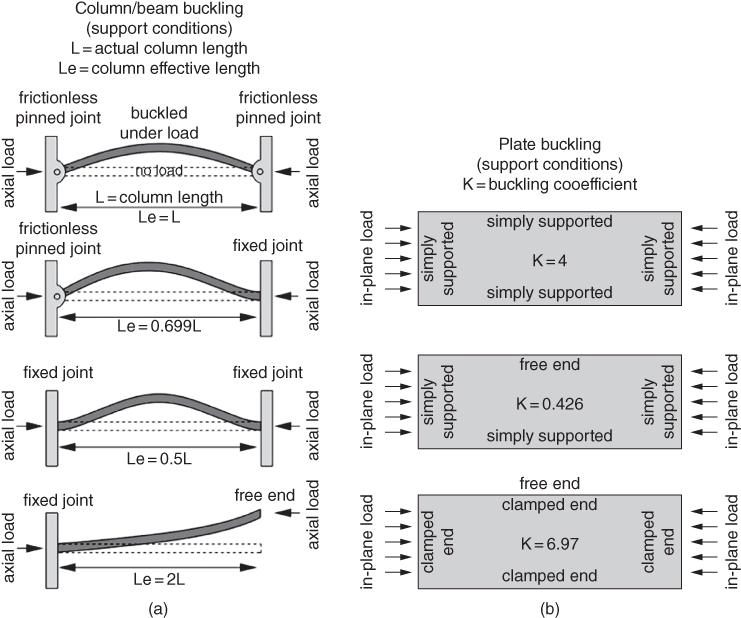
Figure 19.17 Buckling. (a) Column/beam buckling. (b) Plate buckling.
19.9.3.1 Column/Beam Buckling
Figure 19.17a shows a basic example of buckling of a slender column; a beam like structure supported at one or both ends, such as the stringers on stiffened panels, are susceptible to column buckling. A long, thin column will generally fail due to flexural or Euler elastic buckling and at relatively low buckling loads. The buckling stress of these columns can be predicted by the elastic Euler equation 13, 14].

where
σCol = Critical column buckling stress.
E = Material Young's Modulus.
Le = Column effective length.
I = Column second moment of inertia.
A = Column cross‐sectional area.
The column buckling stress is dependent on the particular conditions at each end, which can be free, or range from simply supported through to fixed joint (clamped). This is accounted for in the above equation by the use of an ‘effective’ length parameter, Le. Figure 19.17a indicates how the column effective length varies with column end boundary conditions.
The boundary conditions on the real structure will vary with joint idealisation and manufacture and assembly methods. More rigid end boundary conditions lead to increased critical buckling stresses. Therefore, for the conservative design of columns constrained at both ends, it should be assumed that the ends are simply supported and that the effective length is equal to the actual column length.
Beams/columns that are shorter and sturdier are more resistant to buckling, but their buckling behaviour can be more complex. In these cases the column failure mechanisms usually involve the interaction of global buckling with localised plastic yielding. Further details can be found in the Secant [14] and Euler–Johnson [1] analysis methods for local‐flexural interaction.
It should be noted that buckling of a beam/column typically constitutes global failure of that structural component and the predicted critical column buckling stress should therefore correspond to an ultimate load condition.
19.9.3.2 Plate Buckling
Flat sheets, supported on three or more sides, can also buckle under in‐plane compression loads. On an aircraft, these flat sheets usually comprise the wing and fuselage skin components, as well as internal spar or rib webs.
Buckling of these flat sheets between the supporting structures, such as ribs, frames or stringers, is typically considered a ‘local’ instability. Buckling of the plate sections may not lead to failure of the structure providing the supporting structure remains stable after the local plate sections have buckled. Such structures are described as ‘post‐buckling’ – the total structure remains stable and safe even when local buckling of sub‐sections occurs.
The critical buckling stress of a flat uniformly thick plate under uniaxial in‐plane compression loading can be found with the following equation;
where
σPl = critical plate buckling stress.
E = material Young's Modulus.
ν = material Poisson's ratio.
t = thickness of the plate section.
b = width of the compression loaded edges.
K = buckling coefficient.
Similar to column buckling, the critical plate buckling stress is dependent on the support conditions on each side of the plate. The more rigid the support constraint, the more resistant to buckling the plate. Figure 19.17b indicates how the plate buckling varies with the end boundary conditions.
The various levels of constraint/support on each side of the plate is accounted for by the buckling coefficient, K. Various external sources describe the definition of these buckling coefficients in great detail ([12–14]), however, Figure 19.17b describes the three main edge support scenarios and subsequent buckling coefficients which should be used for conservative structural design.
As noted before, a larger stable structure can accommodate local plate buckling of its secondary elements. These ‘post‐buckled’ structures can offer considerable weight savings, however, the local reduction in stiffness and deformation of the flat plate geometry must be taken into consideration. For example, buckling of the external skin on a commercial aircraft skin can have significant impact on aerodynamic performance. Subsequently, local buckling of the wing skin on a commercial aircraft would not typically be allowed below the limit load. However, on the external fuselage skin where the aerodynamic surface is less influential, local plate buckling could be allowed to occur as low as 50% of the limit load.
The methods outlined here model the plate and column buckling assuming that the column or plate behaviour is ideal. In reality such perfect conditions are rare and more often than not the column or plate structure has built in imperfections or is loaded out‐of‐plane caused by general misalignment of the loads. Any geometric imperfection or loading eccentricity will cause the structure to buckle at a critical stress lower than that predicted using these methods.
19.10 Materials – General Considerations
The preceding sections emphasised general principles for consideration when choosing a material for an aircraft design. In this and the following sections, it is worth reviewing some of the key characteristics of materials relevant to aircraft manufacture: metals and alloys, wood, fabric and composite. This is not meant to be an exhaustive guide, but will hopefully provide the reader with some basic knowledge and issues to consider when selecting a material.
Within the general classes of material, there are subclasses of product as alloys, composites and so on that offer appropriate properties to suit the product. In the materials marketplace, there is a huge variety, and it is ever increasing in number with the newer types, which exhibit better properties with every new generation. At the conceptual design phase, engineers must screen and rank the types of materials that would suit their requirements spelling out the limitations and the constraints involved, and if required, change to another type. In the civil domain, designers will typically stay in safe territory with known and common materials that reduces commercial risk. However, military aircraft material often use case‐specific material never tried before as they strive to deliver technical advantage.
In general, to select suitable material for a component, the following aspects need taken into consideration:
| Property | Production | Operation |
| Strength | Availability | Erosion, wear and abrasion quality |
| Stiffness | Fabrication ease | Thermal and electrical characteristics |
| Toughness | Manufacturability | Plating/galvanic/paint compatibility |
| Crack propagation | Handling | Compatibility with contact material |
| Ageing and corrosion | ||
| Tolerance to environment |
As described in the previous section there are usually a number of options available to choose from. It is always a compromise, because many properties work against each other. This makes aircraft weight and cost estimation more complex, and typically engineers will have to identify and compute large number of parts to estimate component weights, and costs, before it is built. It is here 3D modelling in Computer Aided Drawing (CAD) helps as components and assembly weights and costs can be quickly computed and the effect of design changes noted.
The semi‐empirical relationship for weight estimation given in Chapter 10 considers an all metal construction. It also indicates how to adjust the prediction if there are some parts made of lighter material. For a rapid method, the OEW may be factored accordingly (only the structural weight is affected – the rest is unchanged).
In most cases designers will look to the most common properties for the initial consideration. As shown in Figure 19.18 initial attention is given to standard properties such as Young's Modulus (material stiffness), ultimate strength and so on. But as per the previous section it is now more common to use ratios of key properties to aid the choice as these give additional insight to the efficacy of the material and structure. In general, for the same Young's Modulus, metals have higher density. But when strength‐to‐weight ratio (specific strength) is considered then composites overtake metals, that is, engineers can get same strength with lighter components even when the higher factor of safety can eat into the weight savings. Metals show better Young's Modulus for the same strength. Metal also shows better fracture toughness for the same Young's Modulus. Another important comparison is the relative cost per unit volume versus Young's Modulus where metal alloys have lower costs. These factors typically make aluminium alloy a much better choice for aircraft than steel, which is counter to the first impression given by typical stress–strain material curves.

Figure 19.18 Comparison of typical aircraft material‐stress–strain relationship.
Although for design detailed material knowledge is not normally expected, some overview is very useful. The stress–strain curves as per Figures 19.6 and 19.18 should be studied and their general form understood as they reveal additional insights to the material and its usefulness. For example, under load (stress) all materials deform (strain), some more than others but can recover to their original shape when load is removed, provided its application is within a limit. Beyond this load level they will not recover to their original shape. (See references [1, 5–7] for details on stress and strain.) It can be seen then that steel has a pronounced necking and elongation phase before final failure whereas composites just break with a brittle failure. These two characteristics are important in design. In the case of the pronounced stretching evident in aluminium and steel, this means that if either material is used for a component such as a flap track, then the failure stress to be used for design is in fact the yield stress, not the ultimate tensile strength, because the deformation of such a component could cause failure of the whole aircraft, even though it itself has not broken. The designer must understand these issues to make appropriate decisions.
As an example of the level of detail needed, consider the typical stress–strain characteristic of aluminium alloy is shown in Figure 19.18. The figure shows that initially the stress and strain relationship behaves in a linear manner according to Hooke's Law which represents the elastic property of the material. Within the elastic limit, the material strength (how much stress it can bear) and stiffness (how much deformation takes place) are the two main properties to be considered by the designers to make material choice, of course its cost, weight and other properties are also the factors to consider. The maximum point within which linearity holds is the yield point. Past yield point permanent deformation takes place, the material behaves as a plastic and the slope is no longer linear. The highest point in the stress–strain graph is known as its ultimate strength, beyond which the component will keep deforming, ending up in a rupture seen as a catastrophic failure. The linear portion gives.
Sometimes raw material is supplied with a small amount of pre‐stretching (strain hardening) with permanent deformation set in which the yield point is higher. Typically, some aluminium sheet metals are supplied with 0.2% pre‐stretched strain built in (see Figure 19.9a). However, with pre‐stretching, the ultimate strength is unchanged. Figure 19.9b compares various types of typical aircraft materials. The steeper the slope indicates higher stiffness, which often has a higher elastic limit. Brittle materials rupture abruptly without much strain build‐up, on the other ductile materials exhibit large strain build‐up before rupture giving warnings of failure. Rubber like material does not have a linear stress–strain relation.
More generally the pertinent properties associated with materials are as follows (some are shown in the graph). At some point in the design of the aircraft all of these properties are needed.
| Brittleness | When sudden rupture takes place under stress application (e.g. glass). |
| Ductility | This is the opposite of brittleness (e.g. aluminium). |
| Hardness | This can be seen as a measure of strength. |
| Resilience | This is a measure of energy stored in elastic manner, i.e. the strain restores when stress is relieved. |
| Toughness (fracture toughness) | This is a measure of resistance to crack propagation. |
| Creep resistance | This is a slow deformation with time under load. Here strain can increase without applying much stress. |
| Wearability | This is a measure of surface degradation mainly when under exposure, such as corrosion. |
| Fatigue quality | Fatigue sets up with alternate cycling of applied load. A good material should be able to dissipate vibration energy for a number of cycles. |
| High temperature strength | Ability to hold strength at elevated temperature. |
19.11 Metals
As an initial pointer, it is worth noting some of the detailed properties of metals. Again, the reader will need to refer to specialist references for details but this should provide a starting point. The strength and other properties vary from material to material. Table 19.4 gives some important metallic materials used in the aircraft industry (there is a large variation – only typical ones are given).
Table 19.4 Properties of various types of material for comparison (typical values).
| Material | Density ρ – lb in−3 | Elasticity, Young's Modulus E – 106 lb in−2 | Ultimate tensile E/ρ | Specific strength | Relative cost |
| Aluminium | |||||
| Aluminium alloys | |||||
| 2014‐T6 Alclad sheet | 0.101 | 10.7 | 68 | 106 | Base price |
| 2024‐T4 extrusion | 0.100 | 10.7 | 57 | 107 | Slightly less |
| 7076‐T6 | 0.101 | 10.3 | 78 | 102 | Slightly more |
| 7076‐T6‐extrusion | 0.101 | 10.4 | 78 | 103 | Slightly more |
| Steel alloy | |||||
| Stainless sheet | 0.276 | 29 | 177 | 103 | More |
| Maraging steel | 0.283 | 29 | 252 | 94 | More |
| H‐11 | 0.281 | 30 | 280 | 107 | More |
| Titanium alloy | |||||
| Lithium‐aluminium alloy | |||||
| Nickel‐alloy | 0.3 | 31 | 155 | 103 | Much more |
| Magnesium‐alloy | 0.064 | 6.5 | 40 | 102 | Expensive |
| Beryllium alloy‐rolled | 0.067 | 42.5 | 65 | 634 | Expensive |
It is worth noting the tensile strength of pure aluminium, especially in comparison with wood that is in fact stronger along the grain. Aluminium really only comes into its own when alloyed with key materials such as copper, which significantly increase the strength. The most modern aluminium alloys are some 10 times stronger than pure aluminium.
As design and manufacturing capability has improved along with new variants of metals becoming available, designers are able to capitalise on some special properties and materials manufacturers invest significant effort in developing new alloys with specific capabilities. For example, at the core of a jet engine temperatures become very high, rising above 600°C. Since the properties of metals degrade with increase in temperature, special alloys of steel and titanium have been developed that retain better strength at elevated temperatures. Components experiencing hot temperature have titanium alloys and stainless steel alloys, which come in many varieties. In the quest to find still better materials, nickel, beryllium, magnesium, lithium alloys have appeared. The more the exotic nature of the alloy, the more is the cost. Typically, an aluminium‐lithium alloy is three to four times more expensive than duralumin (2005 price level). But aluminium alloys are still the dominant material used in the aircraft industry. There is a variety of aluminium alloys indicating a wide range available for specific usages. Various kinds of aluminium alloys are designated (classified) with numbering system as given in Table 19.5.
Table 19.5 Aluminium alloys (there are other types without numerical designations).
| Series starting with 1xxx | Pure aluminium |
| Series starting with 2xxx | Aluminium + copper (e.g. 2014‐T6 Alclad sheeta, 2024‐T4 extrusion etc.) |
| Series starting with 3xxx | Aluminium + manganese |
| Series starting with 4xxx | Aluminium + silicon |
| Series starting with 5xxx | Aluminium + magnesium |
| Series starting with 6xxx | Aluminium + magnesium + silicon |
| Series starting with 7xxx | Aluminium + zinc – high strength, heat treatable, prone to fatigue (e.g. 7076‐T6, 7076‐T6‐extrusion etc.) |
aBoth the surfaces of the aluminium alloy sheet are cladded with copper. These have high electrical and thermal conductivity, corrosion resisting, good formability and are not heat treatable.
In choosing an alloy for use the temper of the material is a critical element to consider. The properties of an alloy significantly change after heat treatment. These are designated with a T after the alloy classification, for example, 2024‐T6. There are 10 heat treatment temper codes T1‐T10. The most common in aircraft are T6 and T8. T6 is solution heat treated and artificially aged and T8 is solution heat treated then cold worked and artificially aged. Table 19.6 shows the ultimate and yield stress values for grades of alloy and the fatigue strengths. Note that in moving from T3 to T8 increases the ultimate stress only a little, but the yield stress a lot. But even more interesting, the fatigue strength goes down! So, if the structure in question was a fatigue dominated zone then T3 would possibly be a better option, all else being equal. In many modern commercial jet aircraft, 2024 is used as a skin material and 7075 as a stiffener material.
Table 19.6 Alloy properties – strength.
| Alloy | Ultimate | Yield | Fatigue |
| Aluminium | |||
| 2024‐T3 | 440 | 290 | 138 |
| 2024‐T8 | 455 | 400 | 117 |
| 7075‐T6 | 572 | 503 | 159 |
| Titanium | |||
| Ti‐6Al‐4V | 950 | 880 | 240 |
Although there is a vast range of exotic alloys available they are extremely expensive. For example, titanium alloy Ti‐6Al‐4V has a tensile strength twice that of 2024 but typically costs about eight times more. This does not at first sight look like a promising value, however, when it comes clear that even above 400°C titanium holds its strength at above 600 MPa the value looks much better.
The data available on material properties under various conditions and tests are vast, and only a materials specialist will really be able to understand the special factors that will make one material win over another. But for most design scenarios, a basic knowledge of the behaviour of materials, and key parameters such as those used here, is sufficient to progress a design.
19.12 Wood and Fabric
Although no longer a prime choice in commercial aircraft manufacture, it is worth some passing notes on wood and fabric as a combination for airframe construction. This is still a valid form and in use in home‐built aircraft and, particularly as environmental concerns become more prevalent, wood is now seen as an environmentally sensitive and sustainable material. From a design perspective, one nice aspect of this form of construction is the clarity in which it represents the structural functions of the elements. Wood is used to take the major structural loads with the fabric forming the skin to transfer the air loads through to the structure and carry some of the shear loads in wing torsion. However, such considerations are not foremost in the mind of the designer who simply wishes to design a good aeroplane.
The difficulty with using natural materials such as wood is that they are subject to variation and open to many problems such as diseases. The wood itself therefore needs to be carefully selected and treated to ensure it is of the best quality. Like metals, it must undergo treatments such as drying to ensure its properties are maximised.
There are four main types of wood used: spruce, birch, ash and Douglas fir. Others of course can be used, but these are dominant. Birch and ash are hardwoods and spruce and Douglas fir are softwoods. These are then quite different to work with for shaping and joining. Laminates are also used for specific purposes particularly to build up structure to carry high loads or reduce stress. Modern machine workshop capabilities mean that home construction can be done to a very high standard with accurate and consistent operations. Glues are an essential part of wood construction and again modern adhesives have improved significantly making wooden construction better and significantly improving structural integrity.
In terms of fabric, in the early days of aviation, cotton, linen and even silk were used as the main skin materials to cover the airframe. These were often doped with starch to make them stiff, the most common of which was sago starch, until cellulose dopes were developed such as Emaillite. Modern fabric is almost always synthetic as these are much more durable materials.
Some study of these older forms of construction is useful for any designer as they expose some of the key aspects of aircraft design. For example, in the early days of aviation the fuselage was a simple exposed frame; its function very clearly set to hold the tail in an appropriate position for manoeuvrability, as exemplified by Louis Bleriot's famous aircraft the Bleriot XI. The function was purely structural. Increased understanding of aerodynamics and the significant increase in drag caused by this open framework led to the use of fabric to cover the frame. The function of fabric being an aerodynamic surface reducing the drag caused by the frame. And so the advent of the stressed skin construction that remains dominant today is clear, and its origins in satisfying a functional need equally clear. There are many such insights to be garnered from thinking about older generation aircraft and modern home‐built aircraft that are constructed with this method.
19.13 Composite Materials
The preceding section on wood and fabric is interesting in the context of the most modern materials available in aircraft manufacture. These wooden constructions were often laminates, made up from layers of material bonded together to act as a single unit. Essentially, this is what is now commonly referred to as a composite material.
By definition, composite material is the combination of more than one material to bring out product line superior to what was used for fabrication of an item. The concept is as old as adobe buildings made of straw fibre in clay as binder, later reinforced concrete is another example as building material. Nature has abundant examples of composite structures in many kind of plants – for example, flax plan fibres (fabric of Irish linen), cane and so on – that show considerable strength along the fibres. Bakelite, a man‐made composite for making small insulating (electrical) components, has been available since the beginning of the twentieth century, but it did not have the physical properties for load bearing structural usage.
As wood became expensive (subsequently with growing concerns on environmental issues), search for synthetic substitute resulted in development of fibreglass reinforced plastics (FRP). Many varieties of FRP appeared exhibiting good strength‐to‐weight ratio, thermal insulation, less corrosion and so on; most importantly, it can be moulded in complex curvatures in a relatively easy manner compared to metal forming. Its practical usage in aeronautical industries gained ground after World War II. It was not in a position to compete with metal to be used in load bearing structures and there was cost involved, but it showed the promise in the search for superior composite materials to overcome the limitations (see later) of FRPs. Today, it has developed to such an extent so that modern aircraft are made of composite materials, some small aircraft are made of all‐composite structures. Composites save weight and are easy to fabricate 3D shapes from. CFRP is the most commonly used composite material.
The fibre element or strand (yarn) of composite materials is made of many filaments. The strands are supported in a matrix resin acting as a binder and this transfers the load to the fibre. The main load bearing material is capable only in the direction of fibre run and hence has unidirectional property. The material is therefore typically anisotropic, unlike isotropic metals that have uniform physical properties in all directions. This book gives only the basics that conceptual aircraft designers should be aware of. For comprehensive coverage on composite materials, the readers may refer to Refs. [2, 10].
19.13.1 Composite Materials, Fibre and Fabric
The fibres are naturally unidirectional with strength along the length. Normally, fibres are woven into fabric, which provides strength in many possible directions. The most common ones are woven orthogonally. The fibres are woven into fabric in such a way that fibres cross each other or in groups, with several possibilities for distributing the fibre properties in different directions as woven. The basis of weaving is to lay vertical (warp) strands and horizontal (weft or fill) stands alternately crossing each other over and under. The woven fabric is then laid in layers sandwiched with resin in between as a bonding compound. In each chosen orientation of fibre pattern to form a composite laminate, the ply number is the number of fabric layers laid.
Some of the most well‐known weave patterns are plain, twill, satin, harness weave, basket weave, unidirectional weave and bidirectional weave. In aerospace usage, the plain, twill and satin weave types are dominant, possibly the twin is the most commonly used. These are briefly described in the following and also shown in Figure 19.19. Other types are not dealt with here.
Figure 19.19 Fabric weave type. (a) Plain weave. (b) A 2 × 2 twill weave. (c) Four‐harness satin weave.
19.13.1.1 Plain Weave
The simplest composite fabric weave pattern is the 1 × 1 plain weave when one warp fibre strand goes over one weft strand, then under the next weft strand and so on as shown in (Figure 19.19a). It has good stability (holding strand position, firmness) and satisfactory porosity but is not so amenable to wrap/drape, it tends to wrinkle, that is, it is relatively more difficult to form curvature. This suits for flat surface board‐like structures.
19.13.1.2 Twill Weave
This is the next level of weave pattern, more than one strand of equal numbers in both the warp and weft directions alternate like plain weave. It is distinguishable by its herringbone pattern texture. When a bundle of two strands of warp intersect a bundle of two strands of weft, this is known as a 2 × 2 twill weave (Figure 19.19b). This maintains its stability and is better than plain weave at forming curvature. This type of fabric is widely used in aerospace industry. If the strand count in warp and weft increase in equally numbers, then the fabric is identified by the number of strands; for example, if there is a bundle of four strands intersecting in each direction, it becomes a 4 × 4 twill weave. Twill is better at forming curvature than plain weave.
19.13.1.3 Satin Weave
This is like twill weave with the difference that the weave pattern warp and weft are not the same. When one weft strand crosses over a bundle of three strands of warp fibre, this is known as a (3 + 1) = 4 harness satin weave (Figure 19.19c – also known as Crawford satin). When the one warp strand crosses over a bundle of three strands of weft fibre this is known as a four‐shaft satin weave. Because there are is large number of strands in the bundle in close proximity, this gives a shiny texture, hence it is known as satin weave. The strand numbers identify the satin weave, for example, five harness or five shaft satin weave. It is the least stable of the three but has better formability.
There is a large number of possibilities to make twill and satin weave patterns. In addition, there are many other kinds of weave pattern not dealt with here.
19.13.2 Types of Synthetic Composite Material Fibre
There are many types of synthetic composite fibres, for example, fibreglass (E‐ or S‐glass), polyester, carbon, aramid (trade name: Kevlar, Nomex, Conex etc.), boron, graphite and so on, with a wide range of physical properties and cost. Selection of material is based on the suitability for the application at low cost. Currently, carbon fibre is dominantly in use.
19.13.3 Matrix Bond for Composite Material Fibre
Although the composite fibres in themselves are strong, and when woven into fabric sheets they provide strength in different directions, they need to be brought together to really become a super strong material. To achieve this, a matrix material is used to bond fibres and sheets together to make a solid structural unit (Figure 19.20). The matrix material is often a resin of sorts, which when cured forms a solid connection between the fibres and helps them all act as a single unit rather than a loose collection of strands or sheets. The matrix is the support and bonding material that acts as adhesive to bind fabric as reinforcement to transfer and distribute load throughout the structure.
Figure 19.20 Layers of composite fabric are bonded together with a polymer matrix (e.g. resin) to form a single solid structure.
The matrix material is therefore a critical part of the composite material. There are three main types matrix as follows.
- Polymer
- Metal
- Ceramic
Composites most often use a polymer matrix, as these resins are more accessible and cost effective. The liquid resin can be more easily poured over the composite fabric and then cured so it sets hard. This type of hard resin is called a thermoset. There is a number of types of resin such as acrylic, polyester or polyurethane, but the most common in aircraft manufacture is epoxy resin. In complex structures the resin is drawn through the woven fabric lay‐up and cured under pressure in an autoclave.
It is of course also possible to have metal and ceramic matrix materials, but these are far less common and remain a very specialist area of development.
19.13.4 Strength Characteristics of Composite Materials
Since the fibre is the dominant load carrying element within a composite lay‐up it is very amenable to designing a material structure that is tailored to specific loading. For example, if most of the end load on a structure acts at 45° then aligning the fibres that way can ensure the material is most effective. This tailoring of the material is one of the most powerful aspects of composites. The challenge, however, is for the analyst to understand fully the many complex loading scenarios and stress distributions in the material to effectively design the material. The governing equations for composite materials are complex and this is no easy task.
The analysis of a composite material to determine failure stresses is an even more complex procedure and even now theories are still being developed that can characterise the failure mechanisms accurately and reliably. Although the fibre is very strong, the resin matrix is far less so and can crack or fail under a much lower load. If such a failure occurs then layers of the composite may separate and no longer act as a unit. This is delamination. There are many other modes of failure, such as fibre pull out, matrix cracking and so on.
As this is such a complicated analysis, most designers use simple approximations to allow some estimation of strength appropriate to this stage in design. Typically, the structure may be treated as a metallic like structure and the stresses compared on a similar basis. This gives an estimate of the potential strength of the structure and hence also its weight. Specialist stress analysts can work through the details at a later stage.
19.13.5 Honeycomb Structural Panels
The preceding sections noted the key materials and general considerations for their use an application in aircraft. When this is brought together with further consideration of the structural configurations and how both geometry (i.e. shape) and material are combined to produce a strong, stiff panel, other ‘types’ of construction become very useful. One common form arises from the need to increase stiffness and bending strength of panels without having to add much weight. By separating the outer skin layers and filling the interior with a strong shear resistant configuration, a structural strength and stiffness increases significantly. The interior layer is made from hexagonal shells and for that reason these are called ‘honeycomb panels’.
Honeycomb panels are extensively used in aircraft industry, mostly of metal fabrication but they can also be made of non‐metals, for example, Nomex/Kevlar core with Kevlar/carbon‐fibre surface skins layers and so on. Honeycomb panels may be seen as composite structure comprising of top and bottom sheets, sandwiched in between a honeycomb core panel glued with adhesive layers (Figure 19.21). It is named honeycomb as it resembles with columnar hexagonal bee‐hive honeycomb. Strength improves with thicker core and skins. A high quality strong adhesive layer is essential, otherwise delamination can occur. Honeycomb panels are orthotropic requiring orientation to suit load application, best applied normally.
These are generally purpose‐built panels to suit applications and are supplied by manufactures in plate form coated with PVDF (polymerising vinylidenedifluoride) film to protect from scratches, corrosions and so on, during transportation and in storage. If required, custom‐made honeycomb panels are designed and manufactured to suit the structural requirements. With appropriate manufacturing process stress‐free curved honeycomb are manufactured. Figure 19.21 shows use of a curved honeycomb panel as the wing leading edge.
Figure 19.21 Honeycomb panel. (a) Honeycomb panel details. (b) Curved honeycomb panel application on wing.
Source: Courtesy: Aircraft Structure (Chapter 1) FAA.
The panel cores can be other shapes than hexagonal, for example, corrugated cores or even foam filler but the hexagonal cross‐section is most efficient. Small aircraft use a wire‐cut foam filler as these are easy and cheap fabricate, yet support loading adequately.
Listed here are some of the advantages and disadvantages of using honeycomb panels.
Advantages:
Honeycomb panels offer the highest strength‐to‐weight ratio for the materials used. They have excellent rigidity at minimal weight and offer high stiffness.
Honeycomb panels act as insulators for noise vibration propagation: they are used as nacelle acoustic liners.
They are light weight, facilitating easier fabrication processes save on labour cost. This also reduces the part‐count and maintenance costs are relatively low.
Disadvantages:
They are not suitable for concentrated high loads.
Manufacturing quality issues may result into delamination, not easily visible.
If not sealed properly, honeycomb panels are prone to water ingress that is not easily detectable and can cause severe corrosion.
Storage of water filling the hollow cells in the exposed panels can occur and weight gain occurs in a hidden manner. If this happens to the elevator, then flying may prove unsafe.
Applications:
Honeycomb panels suit normal distributed loads. High concentrated load applications should be avoided. The following are some examples of typical applications in aircraft industries.
| 1. Fuselage floorboards | 6. Doors |
| 2. Control surfaces | 7. Overhead storage doors |
| 3. Nose cone/radome | 8. Galley, furnishing structures |
| 4. Tail cone | 9. Cabin interior panelling |
| 5. Nacelle liners/cowlings | 10. Support structures |
19.14 Structural Configurations
Having considered some of the materials that could be used in the design, the next issue is the overall configuration of the structure: that is, the components and sub‐structures when assembled together form the overall airframe. This is important at this point for two reasons. First, with clever design of the structure, much weight can be saved (or lost with poor design). Second, the arrangement of internal members can affect the space available for important things like fuel, control systems, control surface arrangements and so on. In this section, a fresh look is taken to examine what is under the skin of the airframe and highlight key points for consideration. In turn, the constituent components under the skin are considered, for example, fuselage, wings, spars and ribs, and as an example of other major structures, the wing‐fuselage junction and the empennage.
19.14.1 Skin
As noted before, in the early days of aviation, most of the structure was an open framework, the wing being the only major element with a surface, being the main lifting surface. As knowledge of aerodynamics, and particularly drag, improved it was recognised that a skin covering the frame enhanced performance significantly. The skin had no structural function, its presence there was to form an impermeable aerodynamic surface.
As structural design methods and philosophies developed, it was recognised that a non‐structural skin was a dead weight and its presence could be used more effectively. By using a stressed skin construction, the skin could help improve structural stiffness and strength. But the continuing growth in the size of aircraft to carry many passengers rather than a single adventurous aviator and, subsequently, the advent of stratospheric flight made the need for a structural skin essential, with the loads in a pressurised fuselage being significantly more testing than in early aircraft. This led to the dominance of the semi‐monocoque form of airframe that is so prevalent today. In this, the skin both performs its aerodynamic function and carries pressure and some bending loads.
In current designs, functionally, the skin transmits aerodynamic forces to the ribs and stringers in the wing, and similarly to the frames and stiffeners in the fuselage. Additionally, it resists shear from both torsional and bending loads.
19.14.2 Fuselage
Chapter 5 deals with geometric considerations of fuselage design. A typical structural layout of load bearing fuselage components is shown in Figure 19.22. They constitute of circumferential ring‐like frames placed to normal and longerons running along the fuselage frame offering structural integrity to withstand imposed load. The skeletal frame is wrapped with a cover, in the figure this is an aluminium alloy skin that also supports tensional load. Figure 19.22b depicts a C‐series fuselage frame in a production line showing frames and longerons, as well the floorboard that supports the passenger cabin and the below‐floorboard container space (also see Figure 7.16b).
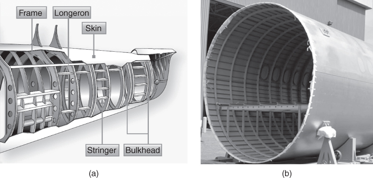
Figure 19.22 Aircraft fuselage structure. (a) General fuselage structure. (b) C‐Series fuselage.
Source: Courtesy: Aircraft Structure (Chapter 1) FAA.
In most modern commercial aircraft the fuselage carries passengers in the stratosphere and it must therefore be pressurised. Of course, for smaller, lighter aircraft, pressurisation is not necessary because the fuselage there mostly has a different purpose, which is to hold the empennage in the right place. In the case of pressurised aircraft, the fuselage is typically circular as this is the most efficient from a stress perspective and is also relatively easy to manufacture. However, in practical terms, a floor is needed to attach seats to and, since this creates an underfloor space, this is used to carry cargo. Consequently, the fuselage is sometimes made slightly elliptical in shape to allow the opportunity to maximise the combination of both passengers and cargo.
Since the fuselage is a pressure vessel it must be sealed. This is done through bulkheads fore and aft (Figure 19.23). The bulkheads are heavy structures. From a manufacturing perspective, it is easier to make them flat stiffened plates, but this is not the most efficient structurally, so they are sometimes made with a slight curvature. This makes them more expensive, but more efficient. Normally, the whole fuselage is pressurised but some aircraft have used a pressurised floor, which is difficult to design and can add weight. Pressure bulkheads cause additional design challenges with the need for cables, ducts and so on to pass through, all of which must be sealed.
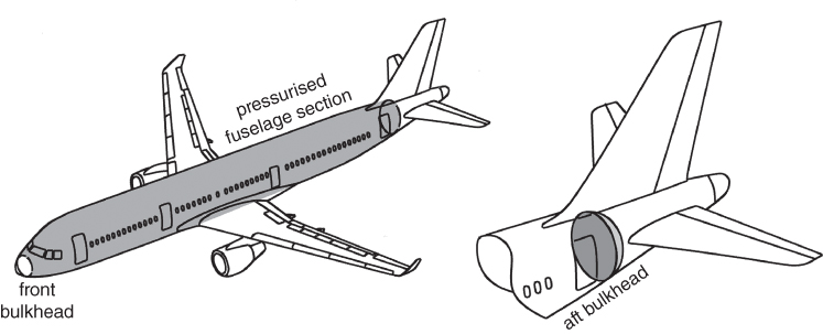
Figure 19.23 Pressurised cabin between two fuselage bulkheads.
19.14.3 Wings
The wing of any aircraft is the critical system to be concerned about. It provides the lift needed for the aircraft to remain aloft and as such has very stringent geometric constraints both in its cross‐section and deflected shape under load, both of which are critical to performance. Under the skin of the wing, the structure is conceptually similar to the fuselage. The main structural element in the wing is the spar. The spar carries the bending loads that are in effect reacting the forces to keep the whole aircraft flying (Figure 19.24). The wing also has stiffeners, more commonly called stringers, in the wing that help the spars with the bending load and help to stabilise the skin to ensure it maintains its aerodynamic shape and does not buckle. It also has ribs periodically spaced along its length that
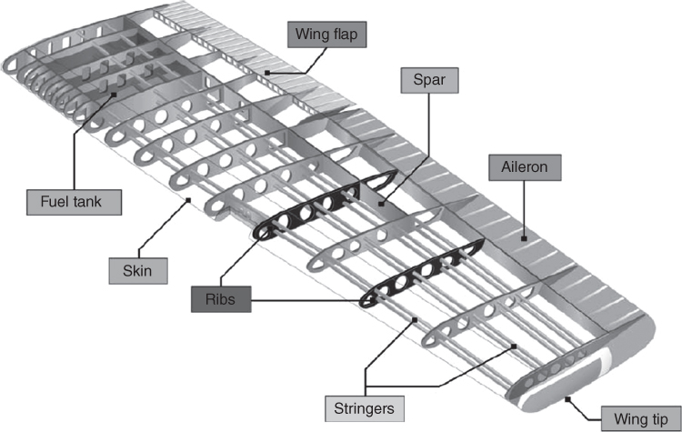
Figure 19.24 Wing structure
Source: Courtesy: Aircraft Structure (Chapter 2) FAA.
maintain the aerofoil shape and help to stabilise the skin and the stringers.
Although the primary function of the wing is to provide lift, this is also where control surfaces can be most effectively placed and where fuel can be stored. In many aircraft, the engines and undercarriage are also hung from the wing, adding both complexity and weight to the structure. At this point in the design though, the key thing to consider is the influence of the control surfaces and the need to store fuel. Both these factors directly influence the strength and stiffness of the wing. In particular, the location of front and rear spars is directly connected to these decisions.
Figure 19.25 shows this. If the location of the rear spar is dictated by the chord size of the main flap (cf), from which it will be attached, then it can be seen that this choice directly impacts the available volume of fuel, if it is stored in the wing centre, and also the stiffness off the wing in that this is now defining the size of the torsion box. Both the torsional stiffness, J, and the shear stress in the skin, τ, are affected directly by the area of the torsion box.
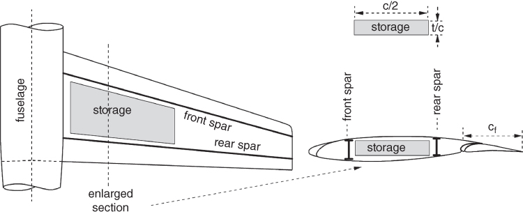
Figure 19.25 Wing planform showing potential fuel storage area.
In many cases, the initial sizes from the concept design show that these choices are all easily accommodated for. However, it is very easy to get to a point where a thin wing, needing a larger flap, has an extended range to cover, and suddenly these calculations and corresponding decisions become very important. This simple check is often omitted by students, but it can cause a rethink in the overall concept of the aircraft.
19.14.4 Spars
The primary structural element of the wing, and therefore arguably for the whole aircraft, is the main spar (Figure 19.26). The main spar is essentially a structural beam that carries the wing bending loads. If the spar can be located and designed correctly much of the rest of the design falls easily into place. The spar can be a single entity but wings often have two, one front and one rear, so that together with the skin they form a closed box, which is very strong in torsion. Much of the structural strength of a wing is due to the torsion box. The spar itself is usually a single machined piece, sometime including lightening holes to reduce weight. In the past it was often built up with many rivets and was a heavy component. The spar is idealised as a beam and designed very much as any typically cantilever beam is designed.

Figure 19.26 Spar types.
Source: Courtesy: Aircraft Structure (Chapter 1) FAA.
Because the wing both bends and twists and, to counter this, the torsion box arrangement (i.e. a box beam) is used, there are usually two spars, one front and one rear. The front one usually takes the greater portion of the bending load and a ratio of 2:3 front to 1:3 rear is a common assumption at this point in the design.
For structural analysis, the spar is usually idealised as a beam with booms and a shear web. The assumption being that the spar caps take all the end load from bending and that the web takes all the shear load. This idealisation is shown in Figure 19.27.
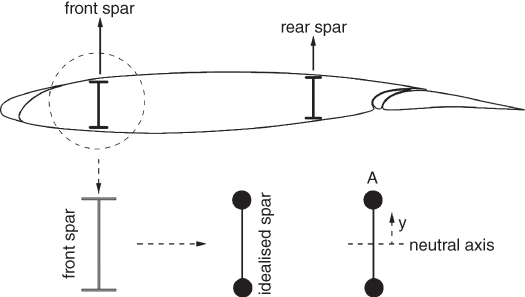
Figure 19.27 Idealised wing spar.
This very simple idealisation is a key concept and allows for a quick estimation of the proposed sizes. It allows for a sanity check on the proposed dimensions of the wing and the material choice. A simple example is shown in Section 19.15 later.
19.14.5 Ribs and Stringers
The main function of the ribs in the wing is to maintain aerodynamic shape of the aerofoil, critical for performance. The ribs act in concert with the skin to distribute the air loads through the structure. They also perform an important stabilising function for the stringers by providing end support for sections and increasing the buckling strength of the structure. Figure 19.28 shows typical wing spars, ribs, stringers and skin.
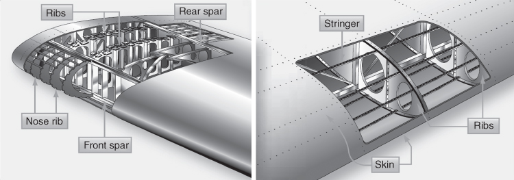
Figure 19.28 Wing Structure.
Source: Courtesy: Aircraft Structure (Chapter 1) FAA.
19.14.6 Fuselage Structural Considerations
Although a circular cross‐section is the most desirable from stressing (minimise weight) and manufacture (minimise cost) points of view, the market requirements for the below‐cabin floor‐space arrangement could result in a cross‐section elongated to an oval or elliptical shape. The Boeing 747 with a narrower upper deck width is a unique oval shape in the partial length that it extends. This partial length of the upper deck helps cross‐sectional area distribution (see Section 5.10.2) and area ruling. Figure 19.29 shows that wing‐box structure passes below the floorboard (near mid‐wing aircraft). It shows underfloor space to accommodate LD3 containers snugly fitted into a circular cross‐section fuselage either side of wing box.
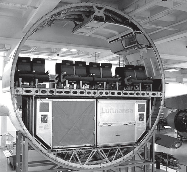
Figure 19.29 Fuselage Structure LD3 container in A300
Source: Wikipedia.
A bulkheads are load bearing frames placed transverse to the hull, in this case these are wall‐like frames placed transverse to the fuselage shell. Aircraft cruising above 15 000 ft altitude need to be pressurised for passenger safety. All large commercial aircraft have a front pressure bulkhead at the nose cone and an aft pressure bulkheads (or rear pressure bulkhead at the tail cone of the aircraft – Figure 19.23) to seal the fuselage shell from the flight deck in front to the entire usable length of passenger cabin in a leak‐proof manner to keep the interior pressurised. Sealing of electrical cables and hydraulic pipes passing through is done as required.
19.14.7 Assembly and Wing Box
Although the preceding sections cover the main elements of the airframe it is worth mentioning two other key elements. The first is the wing carry through box that is prevalent in modern jet aircraft. As noted previously, the torsion box, that is, the section between the front and rear spars, is the key load carrying structure in the aircraft. To maintain structural integrity, this box normally runs through the fuselage and maintains its structural form. The idea being to allow the spar to run interrupted from wing tip to wing tip as any joint will reduce structural strength. There are exceptions to this, but they are all known to be very difficult design challenges. Interestingly, in larger aircraft, the design of the carry through itself is a major design challenge due to the loading intensity at this point.
Figure 4.7 shows typical choices for wing position in relation to fuselage. Figure 19.30 shows wing‐box structure passes below the floorboard (near mid‐wing aircraft).
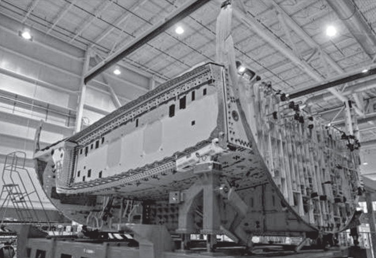
Figure 19.30 B787 wing‐box structure. Courtesy Boeing.
Where the wing meets the fuselage is also a challenging structural for the fuselage. In this case the main fuselage frames here must react the wing shear and torsion loads. Typically, the frames will be very heavy and attached to the wing structure with pins to ensure that only direct axial loads are transferred into the frame itself.
19.14.8 Empennage
Structurally, H‐ and V‐tails are like small wings with smaller planform areas and aspect ratios carrying considerably less load, just what is required for stability and control. They are not. practically required to contribute to aircraft lift, hence there is no requirement for high lift devices. However, the control load has to be sustained by a long and strong fuselage.
The wing joint to the fuselage must ensure the fuselage shell keeps the passenger cabin space to offer maximum passenger space for comfort and movement, hence where and how it is attached requires careful consideration as discussed in Section 4.4.2. This is not the case with the empennage mounted at the tail cone where its narrow volume only houses the control linkages and accessories. Empennage structural layout does not interfere with positioning of control linkages and other devices. While there is similarity with wing structures, the empennage structural design is simpler.
The V‐tail is attached to the fuselage at the aircraft symmetric plane; typically, its spars are attached to the near circular fuselage frames. It looks like a banjo and is loosely known as banjo‐frame (Figure 19.31a). The rudder is kept free by hinging along the fin trailing end.
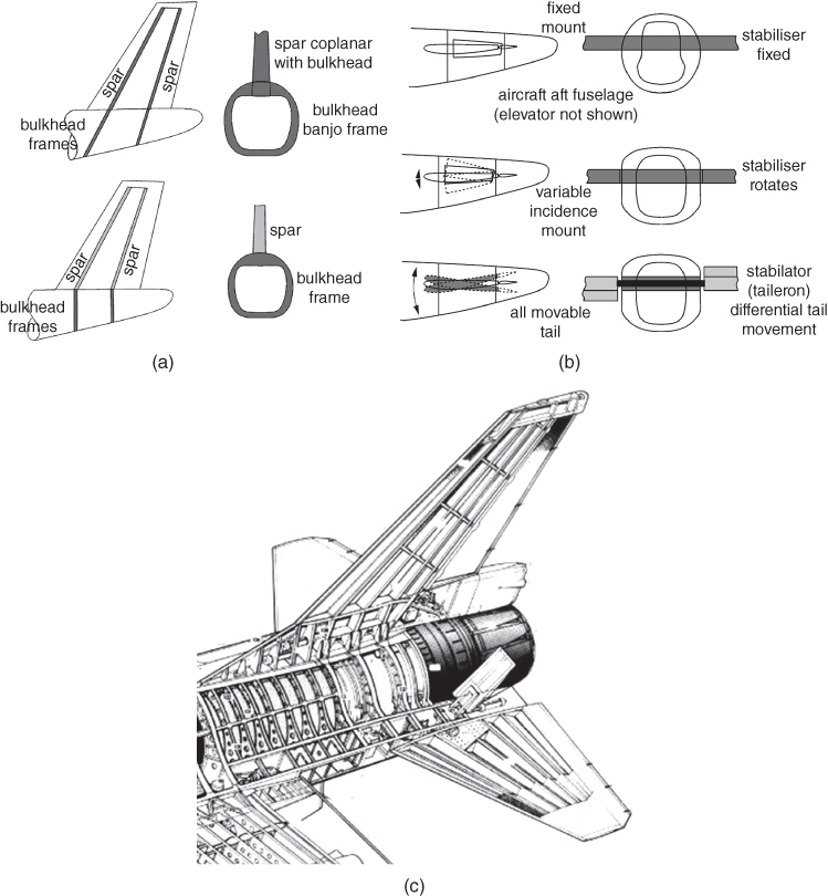
Figure 19.31 Typical choices for empennage joints. (a) Vertical tail. (b) Horizontal tail. (c) Multi‐spar empennage.
Source: Reproduced with permission from Cambridge University Press.
Structural considerations of the H‐tail attachment to the fuselage are dictated by its position with respect to the fuselage, arising from aerodynamic, stability and control considerations. Aerodynamic loads generated by the empennage require a strong and stiff fuselage structure so that fuselage flexure does not adversely affect empennage control effectiveness. The attachment joint H‐tail requires special considerations because part or the whole of the H‐tail can be movable (Figure 19.31b). The H‐tail attachment could be at the fuselage (low tail) or at the V‐tail (T‐tail/mid‐tail).
A multi‐spar empennage arrangement is shown in (Figure 19.31c).
19.15 Rules of Thumb and Concept Checks
One of the key questions asked at this point in the design process relates to why this is of concern. Having an idea of the overall concept is often considered to be enough and the rest is a detail for later. However, as noted in this chapter, such a philosophy can lead to error and major issues for the design later in the process, sometimes to an extent that cannot be reversed.
In addition to becoming generally informed about the potential materials and structural configurations at this point, it is possible to use these principles and key items of information to carry out a sense check on the major dimensions and assumptions in the design. These are based on sound structural theory and do not require detailed knowledge of the other aspects of performance.
So, key things that can be checked are:
- What is the maximum bending moment and shear force at the wing root?
- Does the structural layout allow for enough fuel?
- Does the initial material choice indicate spar caps of a reasonable size?
- Is the wing stiff enough?
At this point, the simple calculations indicate that the size of the structure with this chosen material is in the order of magnitude expected so at this point the design could proceed with this basic concept. However, perhaps there should be some caveats to note for the design team. Although the limit load factor is used as safety factor when the area for the spar booms was calculated, the assumption was that the material was fully stressed. To keep the material within stress limits the size of the spar caps looks a little too big and the deflection of the wing tip a little too much.
So, based on the figures used here the overall sizing looks reasonable and maybe this design can proceed as is. But in most cases, while this can be worked through with a more detailed structural design, it would be worth considering a variation on the wing configuration, either by adjusting the performance, changing the wing planform, changing the material or adding a wing strut to reduce the bending loads. It is worth noting that the real Cessna172 and many aircraft like this have struts to provide additional support for the wing.
The same procedure can be followed for other types of loadings, say torsion and so on. The first task is to compute the maximum stress (normal/shear) and then size the component to withstand the load with safety factor incorporated.
This is the key result here. Some simple calculations have affirmed the sizes of structure for the chosen material are a reasonable starting point, but a question has been raised to the design team that maybe other options either at concept level or detail level should be considered. The team thus has now quantified data on which to base further design decisions and studies. At this early stage of design, this is about as good as can be expected with much further detailed work on all aspects needed to resolve all the uncertainties and finish with a robust aircraft.
19.16 Finite Element Analysis (FEA)/Finite Element Method (FEM)
As modern computational tools have developed, many basic equations have been embedded in computer programmes, but in industry far more sophisticated computational methods are used to obtain more detailed stress and structural loads data. In this introductory chapter, the role of FEA/FEM is only briefly described. In industrial usage, the terms FEA and FEM are synonymous. The FEM is the underlying theory and approach that is used in FEA processes. Industrial application of FEA/FEM is relatively new but has now become the dominant approach for structural design. Although the method was only developed approximately four decades ago, it has now matured to the point where the entire airframe can be analysed in detail.
The FEM has been built upon basic structural theory from continuum mechanics to enable complex geometries and behaviours to be solved. Essentially, the geometry is divided up into small pieces, usually triangles and rectangles or hexahedra and tetrahedra in solids, so that a system of simple equations can be generated to allow the solution to be found in a piecewise or bitesize fashion. The advent of computers has made this a very powerful approach. Sophisticated software applications can do this subdivision (called meshing) very quickly, and automatic solvers can solve the resulting equations in many cases almost instantaneously. In a modern industrial aerospace company it is common to find the internal loads and stresses for linear static loads for the entire structure, and to do this for more than 250 000 load cases. It is a level of detail unimagined by previous generations of engineers, but the underlying principles remain the same.
Finite element systems have also advanced to a point where complex non‐linear problems such as buckling, contact and fracture can be analysed and, more recently, multi‐disciplinary analysis with aerodynamic loads, thermal loads and electromagnetic loads are all being considered for the one airframe structure.
However, the effort needed to build the computer‐aided geometry and ready the models so that this automatic meshing and analysis can take place remains a major effort and, as such, idealisations and simplifications as used in this book are still very necessary at the conceptual design stage. These very advanced tools are used more extensively in the preliminary stage and completely dominate work in the detailed design stage.
Figure 19.33 is an example. However, in aerospace (and other safety critical industries) structural stress analyses must be validated by physical testing. Such strength tests are mandatory requirements by the certification authorities to allow the first flight.
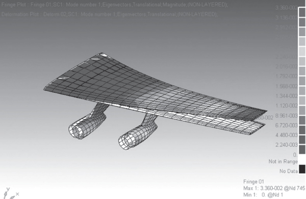
Figure 19.33 Wing FEM analyses – shades indicate stress levels explained in the side bar.
It can be seen that FEM is a subject on its own. Today, all academic institutes offer the introductory courses at the undergraduate level, as an essential topic of study. However, both designers and structural experts all still carry the fundamentals through and these remain the foundation for supporting key design decisions.
References
- 1. Michael, C.Y. (1996). Composite Aircraft Structure, 3e. Hong Kong: Commilit Press.
- 2. Michael, C.Y. (1988). Aircraft Structural Design. Hong Kong: Commilit Press.
- 3. Bruhn, E.F. (1965). Analysis and Design of Flight Vehicle Structures. Tri‐State Offset Company, Cincinnati.
- 4. Megson, T.H.G. (2016). Aircraft Structures for Engineering Students, 6e. Oxford: Butterworth‐Heinemann.
- 5. Benham, P.P. and Crawford, R.J. (1996). Mechanics of Engineering Materials, 2e. New Jersey: Prentice Hall.
- 6. Popov, E.P. (1998). Mechanics of Materials, 2e. New Jersey: Prentice Hall.
- 7. (2003). Material Data Book. Cambridge, UK: Cambridge University Engineering Department.
- 8. Ashby, M.F. (2005). Materials Selection in Mechanical Design. New York: Elsevier.
- 9. Ashby, M. F., Granta Design, Material and Process Selection Chart, CES 2009. EDUPACK, Engineering Department, Cambridge, UK, 2005.
- 10. Baker, A., Dutton, S., and Kelly, D. (2004). Composite Material for Aircraft Structure, 2e. Reston, USA: AIAA.
- 11. Pora, Jérôme. Composite Materials in the Airbus A380 – From History to Future, Airbus, Large Aircraft Division 1 Rond Point Maurice Bellonte 31707 Blagnac Cedex, France, Proc. of the 13th International Conference on Composites (ICCM‐13), Beijing, China 2001, 1–10.
- 12. Becker, H. Handbook of Structural Stability, NASA Technical Note, NASA‐TM‐89720, 1957.
- 13. Bulson, P.S. (1970). The Stability of Flat Plates, 1e. London: Chatto & Windus.
- 14. Timoshenko, S.P. and Gere, J.M. (1961). Theory of Elastic Stability, 2e. McGraw‐Hill Book Company Inc.