
The electronics for the speaker system can be split into two main sections—the power circuit and the audio circuit.
The circuit structure of the electronics is shown in the following diagram:
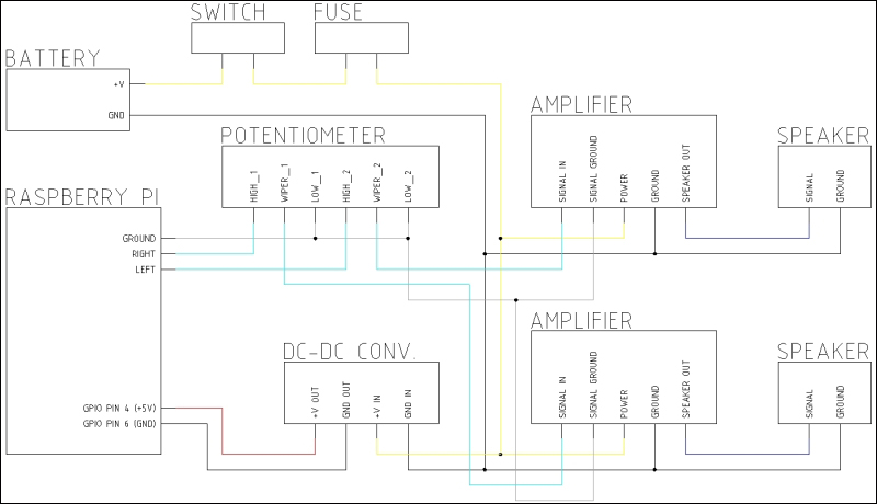
The speaker system block diagram
Note the color coding of the wiring. Here, black shows the power ground, gray shows the audio ground, cyan shows the unamplified audio, blue shows the amplified audio, yellow represents the battery voltage, and red shows 5 V.
Note the color coding of the wiring. This is important as it is the most common way in which different signals and power supplies are identified within an electronic product. There are a few common conventions that, while are not used here, are good to know; black is always ground, red and yellow usually indicate a power supply (5 V and 12 V, respectively), and yellow and green stripes usually represent a mains earth.
For small projects, such as this, following a standard color code for wiring is not as important. Different signals have a colored wire of their own to make identification and troubleshooting easier.
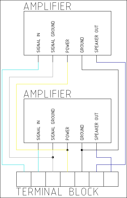
Firstly, we will wire the two mono amplifier modules to a strip of terminal blocks to make a stereo amplifier module. This is done by connecting the common connections from each amplifier together and keeping the signal and output connections separate, as shown in the following diagram:
Next, take the volume control and solder the wires onto it in the configuration, as shown in the following diagram:
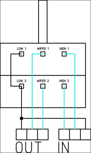
The audio input wires should be relatively short (around 50 mm) and connected to a strip of three terminal blocks; the output should have enough wire to reach the amplifier module (around 150-200 mm). This volume control is essentially comprised of two potential dividers with their wipers fixed together such that each potential divider is always at the same position.
Now, we can solder wires to the 3.5 mm audio jack; since this is a bit smaller and it will only carry the unamplified audio signal, we can use a 32 AWG wire for this:
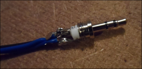
The audio connector can now be connected to the terminal block on the volume control; at this stage, the orientation of the left and right channels is not important.
Then, connect the output from the volume control to the first three connections on the amplifier terminal blocks; again, the orientation is not important at this stage.
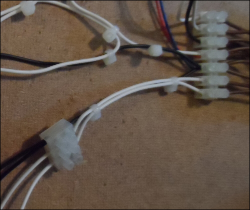
Since the power ground connection on the amplifier will have to be connected to both the speakers, the battery and the DC-DC converter to power the Pi will be best to extend the speakers connections to their own strip of terminal blocks. This will reduce the number of connects that have to be made in the same connection.
This is simply a case of adding a short length of wire (around 50-100 mm) to the two speaker outputs and power ground from the amplifier terminal blocks and connecting them to a strip of three terminal blocks:
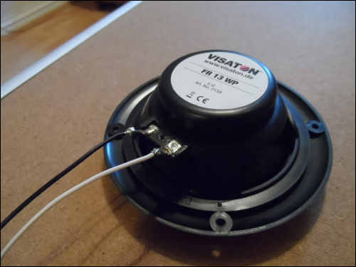
Next, we need to solder a wire (around 300 mm) to the two speakers. Note that the speaker will have markings that show the correct polarity it is to be wired in:
Now, connect each speaker to the strip of three terminal blocks coming from the amplifier modules. Once again, the correct speaker orientation is not important at this stage.
This is all with respect to the wiring for the audio section of the speaker system.
Since the battery we will use is rated at 14.4 V, we are able to power the amplifier directly from the battery. However, the Pi must be powered with 5 V. So, we will need a power converter to be able to power the Pi using the battery.
The power converter we will use is a DC-DC switch mode converter, which will accept input voltage from the set output voltage up to 35 V. Therefore, we will continue to power the Pi as the battery voltage drops while under heavier load (for example, when playing at higher volumes) or as the battery starts to drain.
As lithium polymer batteries can be very dangerous if used incorrectly, it is vital that a fuse is used in line with the power switch to protect the battery just in case there's a fault in the speaker system. A rating of around 0.8 to 1.5 A will be suitable for this purpose.
We will start with powering just the amplifiers. This is a fairly simple task as all it involves is connecting the battery positive terminal to the power connector on the amplifier terminal blocks via the switch and fuse. The ground is connected directly, as shown in the earlier diagram. Perform the following steps to connect the circuit:
- Take the connector for your battery, and assuming that it has leads presoldered onto it, connect them to a strip of two terminal blocks. If they do not have leads soldered onto them, then this should be done first using a short length of wire (around 50 mm).
- Solder a 100 mm length of wire onto one pole of the power switch and connect the other end to the positive terminal on the battery terminal block.
- Solder a 50 mm length of wire from the other switch pole to one contact of the fuse.
- Solder a 50 mm length of wire from the other fuse contact and connect the other end to the positive power connection on the amplifier terminal blocks.
- Connect the grounds of the battery terminal block and the amplifier terminal blocks with a 100 mm length of wire.
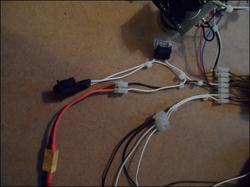
Once these steps have been completed, the setup should look like what is shown in the following image:
Now would be a good time to give the audio electronics a test by connecting the battery and powering on the amplifiers. You can either use the Pi powered from a USB or any other media player as the audio source. It is best to have the volume control set to its lowest setting and gradually increase it.
Next, we want to power the Pi from the battery using the DC-DC converter. There are two main ways of doing this: either by applying power to the GPIO header or by back-powering the Pi using a powered USB hub. In this case, I will be powering via the GPIO header, which will likely be sufficient for what we are doing here. Powering using a powered USB hub will only be needed if you are using an external hard drive to store the music library.
First, we need to solder wires to each of the terminals of the DC-DC converter and note the polarity of the connections to ensure that the color coding of the wiring is consistent. A length of around 100 mm is sufficient for each connection.
Next, connect the positive and ground connections on the power input side of the converter to the positive and ground connections on the amplifier terminal blocks, and connect the two leads from the output terminals of the DC-DC converter to a strip of two terminal blocks.
Now that we have the DC-DC converter connected, we need to set it to the correct output voltage before we connect it to the Pi. To do this, set a multimeter to the voltage mode and place the probes across the two connections on the terminal blocks connected to the DC-DC converter's output (if possible, screw the tips of the probes into the terminal blocks to avoid having to hold them in place). Turn the power on, and if needed, adjust the range on the multimeter.
Usually, I find that these converters come preset to the output just below the input voltage, which would be far too high for the Pi, which is designed to operate at 5 V. In order to adjust the voltage, use a small, flat-head screwdriver to adjust the square blue potentiometer. This is a multiple turn potentiometer, so do not be surprised if it takes a few rotations of the potentiometer for the voltage to change. A reasonable voltage to aim for is 5.1 V, as under load, the voltage is expected to drop slightly.
Once the voltage is corrected, turn the power off, remove the multimeter from the output of the DC-DC converter, remove one end of two 0.1 inch jumper leads, and connect them to the terminal block on the output of the DC-DC converter. Connect the positive lead to pin 4 of the GPIO headers on the Pi and the ground lead to pin 6.
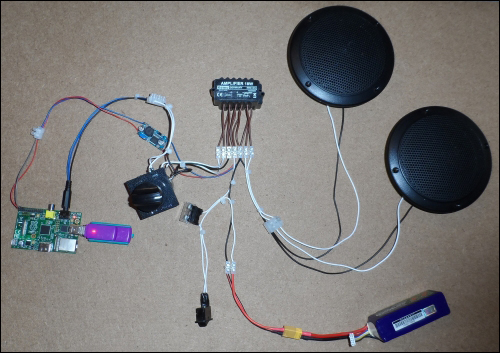
By now, the setup should look similar to the following:
Once this is done, apply power once more and within a few seconds, the Pi should start booting up. If it does not, turn the power off immediately to prevent possible damage to the Pi and battery, and double-check all of the wiring against the block diagram shown earlier in the chapter.