
Firstly, it is important to have a good idea of the dimension that we need for each part of the cabinet. The following diagram shows the dimension of the cabinet I made with the height and width of the monitor. While you are free to adapt the design to whatever style you like, be aware of the dimensions that are likely to change throughout the design. In the following diagram, note that all the sizes are in mm:

Note that the angle between the monitor and joystick panel is not fixed, as it will depend on the size of the monitor and joystick/button panel. The dimensions listed in the diagram are only a rough guide and you are encouraged to draw a side panel out in a scale of 1:1 to check the dimensions before deciding on them.
The first parts we want to cut are the two side panels for the enclosure. These will both be cut from a 12 mm plywood. As we will be using a jigsaw to cut the panels, we will cut both the left-hand side and right-hand side panels at the same time, since it is very difficult to get exactly the same cut twice when you're guided by eye alone.
For this, we need to ensure that the two sheets of plywood do not move relative to each other during the cut. There are multiple ways to do this, but the way I chose was to screw the two sheets together at regular intervals just outside the cut line (refer to the following image). This is probably one of the best ways, as this method of fixing is very easy to remove and will withstand a lot of force (more than you will ever exert on it while sawing) before the sheets start to move.
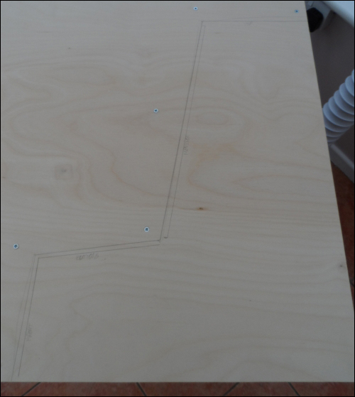
Once both the sheets of material are fixed together, you will need to mark out the cut path in faint pencil markings on one side of the material. Ensuring that this is as faint as possible will make it is easier to remove any leftover markings while sanding the panels down later.
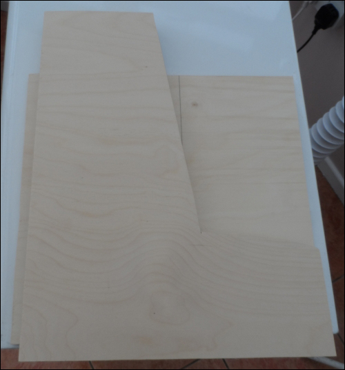
Once the panels have been cut out as shown in the following image, they will have fairly untidy edges, especially when you cut against the grain of the top layer of material. As each panel is made, it is a good idea to take a piece of a low-grit sandpaper (around 40-60) and quickly remove any untidy edges. When it is time for the panel to be assembled in its final position, you should take time to sand the edges and surfaces with progressively higher grip sandpapers to achieve a smooth and tidy finish. A good progression would be 80, then 120, and then 240.
Next, we will cut the bottom panel of the cabinet. Also, cut from the 12 mm plywood, as shown in the diagram at the start of this section. The width of this panel will be around the width of the monitor plus 10 mm, and the depth will be whatever the desired width of the cabinet is (in the case of the diagram, it is 400 mm).
As with the side panels, they should be sanded down to remove any rough edges. However, as only one edge will be exposed to the front of the cabinet, getting a perfect finish here is not essential.
Next, we will attach the bottom panel to the two side panels. To do this, we will use both screws through the side panels that go into the edge of the bottom panel and several plastic assembly fittings like the ones shown in the following image. This will help to ensure a good quality, durable joint.
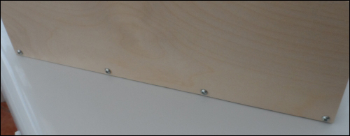
First, place the bottom panel on a flat surface and align the one side panel next to the matching edge of the bottom panel. Next, drill a series of pilot holes that are around 1-2 mm smaller than the screws that will fix the two panels together at regular intervals along the edge of the side panel. They will also screw the side panel to the bottom panel, as shown in the following image. The screws used here should be dome-headed, self-tapping wood screws around 1.5 inches long. Here, it is important to ensure that the pilot holes are deep enough to prevent the plywood from splitting as the screws are inserted.
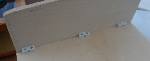
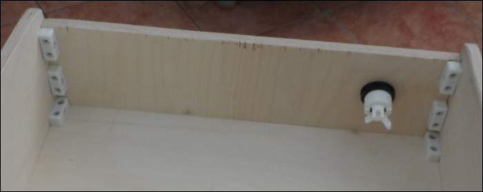
Next, on the inside of the cabinet, screw several of the plastic assembly joints at the corner between the two panels by using countersunk self-tapping wood screws around 3/4 inch long. Ensure that around 30 mm of space is left at each end to give enough clearance for other panels and their assembly joints, as shown in the following image. Repeat this process for the second side panel:
Next, we will cut the panel that will hold the monitor in place. This panel needs to be around 150 mm high, the same width as the bottom panel, and cut from 12 mm plywood. This can be marked out and cut in the same way as the other panels.
Once you've cut out the panel, follow the next diagram to mark out the four holes that will be needed to attach the monitor. Here, I am assuming that the monitor uses the VESA 100 standard, which is the most common size found on 15-22 inch computer monitors. It would be worth checking this standard when you're looking for a monitor for this project. VGA monitors with this type of mounting are very common on Internet auction sites and often sell very cheaply. Note that the following diagram is not to scale and that the center of the panel is indicated by the red cross:

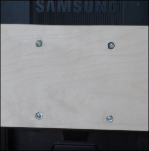
Once the VESA holes are drilled, you can prepare the monitor to be mounted on the panel by removing any desk stand it had (the procedure for doing so varies for each monitor; it is worth searching online if it is not obvious to you how it can be removed). Attach the monitor using four M4 machine screws in the holes you've just drilled, as shown in the following image. It is important to use a washer on both sides of the plywood panel to help spread the weight of the monitor and to prevent the screw heads from digging into the plywood.
Next, we will attach the monitor mount to the two side panels. To make the positioning of the monitor easier, first, tip the cabinet to its side so that the monitor's weight is supported. Now, move the monitor panel until the monitor is in the desired position. This should leave at least 5 mm at the top for cooling and the bottom should be just above where the button panel will be.
Now, attach the monitor panel to the two side panels using two assembly joints on each side of the panel. This will keep the panel in place for now. However, as with the bottom panel, we need to add some longer screws that go through the side panel to provide enough support for the weight of the monitor.
To do this, unscrew the monitor and mark the outline of the monitor panel on the inside of each side panel and then remove the screws holding the assembly joints to the side panels. This will leave an indication that the panel was mounted.
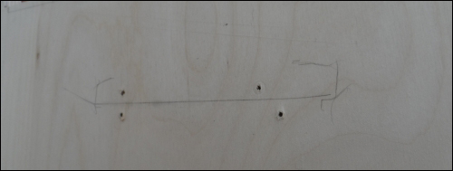
Next, drill two holes in each side panel that will be used to guide the screws into the side of the monitor panel, as shown in the following image. It is important here to ensure that the position of the holes will not cause the screws to collide with the screws already in the panel from the assembly joints.
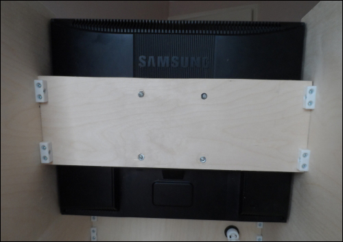
Once this is done, reattach the monitor panel with the assembly joints and use the holes drilled in the side panels to drill pilot holes in the edge of the monitor panel, similar to what was done in the bottom panel. To finish, screw two of the same screws used for the bottom panel into each side of the monitor panel and reattach the monitor. By now, the back of the cabinet should look similar to what is shown in the following image:
Next, we will cut the front, top, and button/joystick panels. All of these panels can be cut from 6 mm plywood and the width of these will be the same as the bottom and monitor panels. The exact width of these will depend on your design, based on the diagram earlier in this section. Once you have the dimensions of the panels, they can be cut in the same way as the other panels.
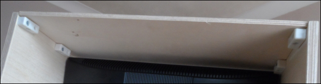
First, we will attach the top panel. This should be mounted on the top between the two side panels and can be held in place with two assembly joints on each side of the panel, as shown in the following image. Since this plywood is thinner, you will need to use half inch screws for this.
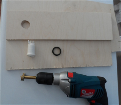
Next, we need to drill a hole in the front panel for the single-player arcade button. To do this, we will use a 30 mm Forstner drill bit. First, start by marking the center of the hole for the button. This will be used to align with the sharp point in the center of the drill bit.
Although holes like this are best drilled using a pillar drill or drill press, they can be drilled using a handheld electric drill (a battery-powered cordless drill is unlikely to have enough power to drive a Forstner bit of this size). It is important to hold the drill as vertical and steady as possible to ensure that the hole does not become out of shape by the drill as it moves relative to the panel.
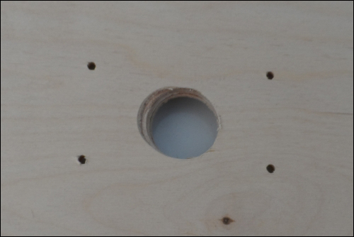
When drilling by a handheld drill, it is best to start slow to ensure that the drill gets a good position in the center of the hole and gradually speed up to do the bulk of cutting. It may take several minutes to fully cut through the panel, and it is worth stopping occasionally to clean any material that has built up on the drill bit. Be careful when doing this, as friction can cause the drill bit to heat up enough to cause burns. The drilled hole is shown in the following image:
Once the hole is drilled, remove any loose material around the edges of the hole using medium-low grit sandpaper (either 80 or 120) and insert the button through the hole. To do this, you will have to remove the micro switch from the back side of the switch. In the switch that I used, this is done by lifting the clips on one side of the switch, which allows the micro switch to be levered out.
Once the switch is fitted and the edges of the panel are sanded down, the panel can be fitted using four assembly joints, as shown in the following image. Depending on the accuracy of the cut, you may find that the panel is a tight fit in between the two side panels. If this is the case, then loosen the screws that hold the side panels to the bottom panel so that the side panels can be moved outwards slightly. This allows the front panel to be inserted easily.
Note that in the preceding image, I used 12 mm plywood for the front panel. While it is possible to do this, it is not required. Drilling the 30 mm hole takes much longer.
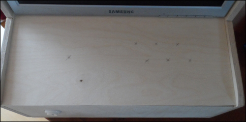
Next, we want to mark the position of the buttons and joystick on the front panel. The best way to do this is to place the panel in position to see which position will feel most comfortable or intuitive to play. Once you have done this, mark the position of the center of each button and the joystick, as shown in the following image:
Now that we have the positions of each part to be mounted on this panel, we can start drilling the holes for them, starting with the joystick.
With the joystick, I recommend that you drill one 30 mm hole for the shaft of the joystick and four 4 mm holes for the mounting screws. Start by drilling the 30 mm hole centered on the mark you made for the center of the joystick. This hole will be cut using the 30 mm Forstner bit in the same way as the hole for the button on the front panel.
Once this is done, insert the joystick into the hole with the switch side on the back side of the panel (you will need to unscrew the red ball from the top of the joystick first) and mark the position of the four holes in the corner of the metal plate. This is where we will drill the holes that will be used to mount the joystick.
After the holes have been drilled, the panel should look something like what's shown in the following image:
We will mount the joystick later on. Now, it is time to drill the holes for our arcade buttons. This is done in the same way as was done for the single-player button on the front panel.
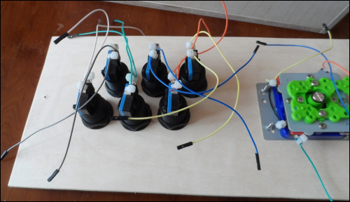
Each of the buttons can now be mounted on the panel. While nonessential, mounting them so that all of the micro switches line up parallel to each other makes cable management easier, as shown in the upcoming image.
Next, we can fasten the joystick in position with four M3 machine screws by using a washer for both the sides of the metal plate on the joystick. Finally, place the round, black disc that came with the joystick over the joystick shaft and reattach the red ball.
By this point, the back of the front panel should look something like what's shown in the following image:
All that is left to do now is to attach the button/joystick panel to the rest of the cabinet. As with all the other panels, this can be easily done by using several assembly joints.
While it is possible to use four joints here to fix the panel in a single position, I found it useful to only attach the panel using two joints at the back of the panel (closest to the bottom of the monitor). This will allow the front panel to be lifted up for easy access to the Pi and wiring, as shown in the following image:
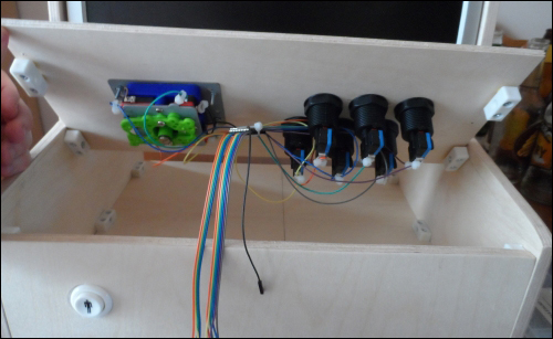
I also chose to use a set of male-to-female 0.1 inch jumper wires to extend the wires that had been soldered onto the button and joystick switches. Again, this is not essential, but may help to make wiring the switches to the Pi easier.
Of course, this is just one possible way to design the case for the arcade cabinet. Here are another two very unique designs of a similar project: