
The first step is to wire up and configure the drive electronics and motors that will move the various parts of the robot arm; this will consist of four micro servos that will move the arm, and two geared motors that will provide drive to the chassis.
The servos are powered by a 5 V power supply and can be driven using a pulsed digital signal (through Pulse Width Modulation (PWM)) from the Pi GPIO ports, which define the position that the arm of the servo is to be kept in.
The motors will be driven using a relay board, which allows the Pi GPIO port to switch the higher currents needed to power the motor. This is just one of the many ways this can be done. Another possibility is to use a MOSFET H-bridge, which will also allow control of the speed of the motors. However, the relay solution is simpler in both code and electronic construction, so it will be used here.
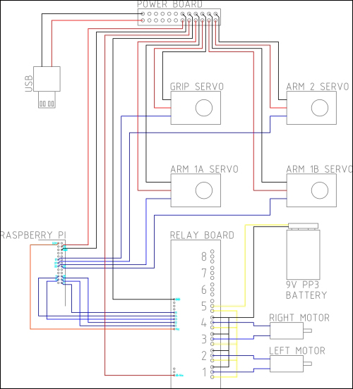
The wiring for the drive electronics is shown in the following diagram:
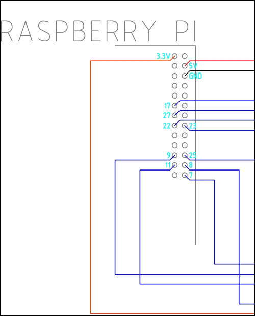
The wiring of the Pi GPIO header is shown in greater detail in the following diagram:
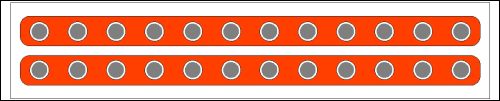
We will start by constructing the power board; this is simply two sets of 0.1 inch pin headers on a small section of the stripboard that will distribute the 5 V and ground power rails. We will need at least seven headers for both the 5 V and ground rails; however, adding more headers will allow possible expansion later.
The board should be laid out as shown in the following diagram:
Now that we have all the parts needed for the drive electronics, we can start assembling them to test with the web application, later in the chapter:
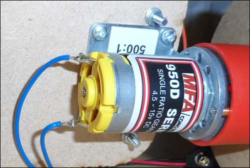
- Solder a 18 AWG wire on to each terminal of both motors, as shown in the following image:
- Take some more 18 AWG wires and wire up the relay board, as shown in the diagram earlier in the chapter.
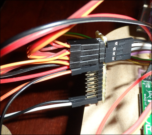
- Connect the motors and PP3 battery clip to the relay board. By now, the board wiring should look something like what is shown in the following image:

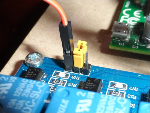
- Remove the small orange pin jumper on the three-pin connection on the relay board; it can be stored by connecting one side of it to the middle pin of this header, as shown in the following image:
- Now, take the power board and connect the four servos to it, as shown in the following image, to provide them with power and leave the signal pin accessible from the side of the board:
- Next, take four male-to-female pin jumper cables and connect the servos to the GPIO header, as shown in the preceding diagram.
- Take the USB cable and cut the cable 10 cm away from the USB A connector.
- Strip the outer insulation and shielding to reveal four wires.
- Strip the red and black wires. These are the 5 V and ground power connections that we will use to power the robot arm from the USB power bank.
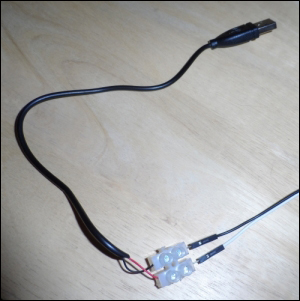
- Connect the wires to the two male-to-female pin jumpers using a strip of two terminal blocks, as shown in the following image:
- Finish off any remaining wiring by following the wiring diagram shown earlier.
Now that the wiring is complete, attach the USB power bank to the USB cable to provide power to the Pi and servos. Ensure that you use the higher output current port on the bank (usually marked as either 2.1 A or used for tablet charging) and connect a 9 V PP3 battery to the battery clip attached to the relay board.