
Now that the electronics and software installation is complete, we can move on to build the plywood enclosure for the mirror. If you do not have access to a router and table for this project, then refer to the Building the mirror without an enclosure section described later in the chapter for instructions on how to construct the display without the plywood enclosure.
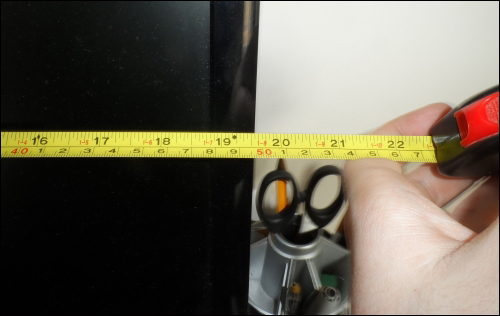
First, we need to measure the monitor to determine both the size of the mirrored acrylic sheet that needs to be ordered and the sizes to which the panels for the enclosure should be cut.
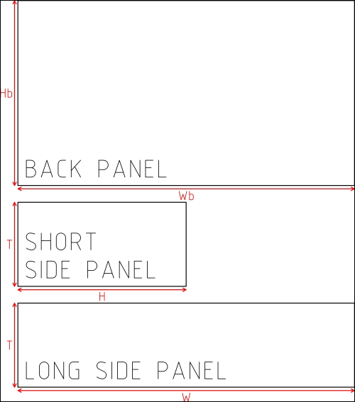
The upcoming diagram shows the panels that must be cut out to make the plywood enclosure. Each of the dimensions are given by the following calculations:
- W = monitor width + 24
- H = monitor height
- Wb = W + 10
- Hb = H + 10
- T = monitor thickness + 9
To construct the enclosure, perform the following steps:
- While taking the measurements of the height and width, it is advisable to leave around 2 mm on each side of the monitor, which will allow us to rectify any errors in the measurement while manufacturing.
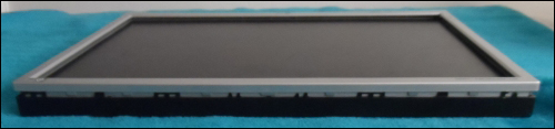
- In order to take the next measurement, we must first remove the front plastic bezel from the monitor. This is usually held on with a series of small plastic clips around the edge of the monitor, as shown in the following image. To remove them, use a small, flat screwdriver to prize open the gap between the back of the monitor case and the front bezel. Gradually, work around the monitor until all the clips are released. The front bezel should now lift off with ease.
- If the monitor has any buttons or LEDs on the front panel, there is likely an additional PCB that must be removed from the front bezel. This usually requires us to unscrew the board.
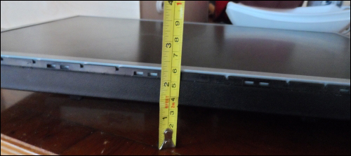
- Once the bezel is removed, we can now measure the space required inside the box for the monitor. This is the distance from the back of the monitor (specifically the VESA mounting points) to the front (preferably level with the display surface), as shown in the following image. It is advisable to add at least an additional 5 mm to this measurement, as it is easy to add washers to move the monitor forward if the panels are cut too large. However, this is impossible to recover if you cut the panel too small.
- Once you have these three measurements, you can substitute them into the calculations shown in the diagram. Using a jigsaw, cut the panels to size. You will need two of both the long and short 12 mm plywood side panels and one of the back 6 mm plywood panel.
- Once these panels are cut, it is time to cut the slots in them to place the mirrored acrylic. This is done using a 4 mm rebate router bit in a router table, which can be seen in the upcoming image. To do this, perform the following steps:
- Firstly, ensure that the router is firmly fixed into the table and the bit is tightened correctly into the router.
- Next, use the router's depth lock to fix the height of the router, so that the lower edge of the blades are around 4-5 mm above the table.
- Now, move the fence so that around 5-6 mm of the cutter is exposed on the front of the fence (that is, the cutter can only cut up to 5-6 mm from the material passed along the fence).
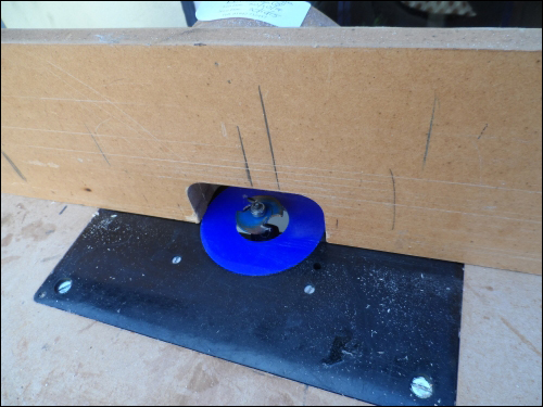
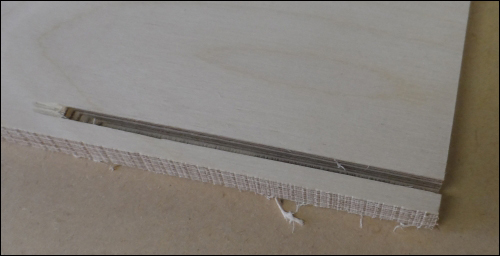
- Once the router and table are set up, it is a good idea to make a few test cuts on a scrap piece of material to ensure that the router is set up correctly. Aim to get a slot that is around 5-6 mm deep into the plywood and around 4 mm away from one edge, as shown in the following image:
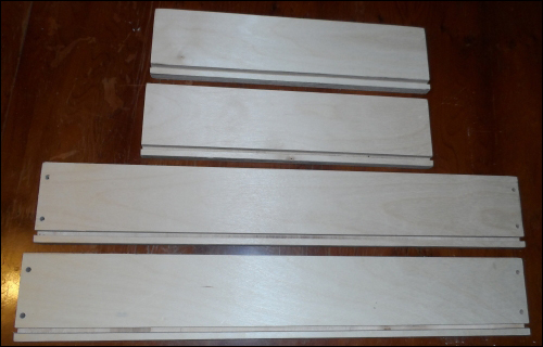
- Once you are happy that the setup is correct, you can machine the actual panels to end up with a set of panels, as shown in the following photograph. At this stage, it is a good idea to sand the panels with some coarse grit sandpaper to remove any ragged edges left by the router or jigsaw.
- The next step is to assemble the four side panels that form the outside of the enclosure. This is done using two screws at each end of the long panels that are screwed into the ends of the two short panels. For this, we will use screws that are at least 1 inch in length, but no more than 2 inch. Perform the following steps:
- First, we must drill clearance holes into the ends of the two long sides to allow the screw shaft to pass through easily. This hole should be just larger than the shaft of the screw, but smaller than the head.

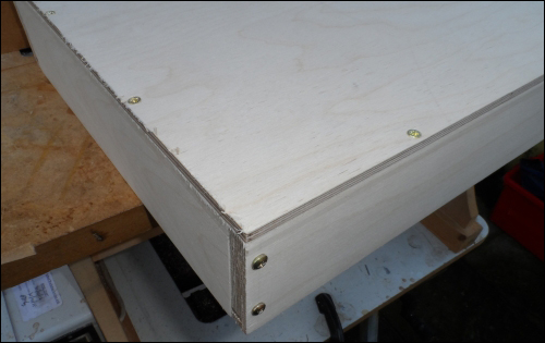
- Next, align one of the long panels against a short one, as shown in the following figure, and use the clearance hole as guidance to drill a pilot hole in the end of the short side panel. This hole should be around 0.5-1 mm smaller than the shaft of the screw.

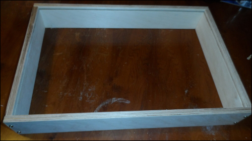
- Repeat the previous step until all the joints have been fastened, ensuring that the slot for the mirror runs all the way around the inside edge, as shown in the following photograph:
- First, we must drill clearance holes into the ends of the two long sides to allow the screw shaft to pass through easily. This hole should be just larger than the shaft of the screw, but smaller than the head.
- The next step is to attach the rear 6 mm plywood panel to the back of the enclosure frame. This can be done using several self-tapping screws around the edge of the enclosure. Note that this panel has intentionally been made larger than what is required.
- Firstly, with the enclosure placed on top of the rear panel, draw around the inside of the enclosure to help mark out the positions for the clearance holes so that the screws hold on to the back panel.
- Next, using this marking as a guide, drill several clearance holes around the perimeter of the enclosure. Typically, two holes on the short panels and three holes on the long ones should be enough.
- Once this is done, drill pilot holes for the screws so that they go into the side panels and attach the back panel to the rest of the enclosure.
- The next step is to trim the excess material from the back panel (the whole idea here was to remove the need for accuracy while cutting and fitting the back panel). This is done using a straight, bearing guided, router cutter.
- Firstly, move the fence toward the back of the router table (we will not use it as a guide here) and fit the straight bit in the router.
- Next, using the depth stop, move the router to a position where the bearing is on the same level as the 12 mm side panels, so that there is enough clearance to allow the cutter to remove the excess material on the back panel only.
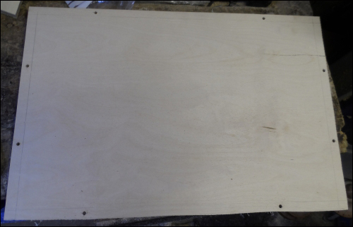
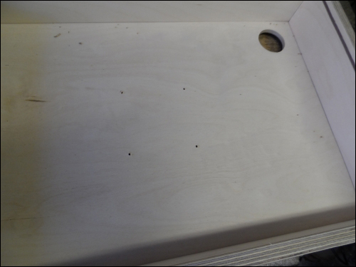
- Now, you can machine away the excess material on the back panel by keeping the enclosure tight against the router bit while making a pass along all the edges of the enclosure. Once this is done, the panel should look similar to the following image:
- The next step is to mark the position of the VESA mounts on the back panel in order to drill the required holes in the back panel. The easiest way to do this is to carefully remove the display assembly from the rear plastic housing, using the following steps as a guide:
- The display assembly is rarely fixed into the plastic housing by anything other than the fact that it is enclosed by. So, if we give enough force, the display panel and electronics enclosure behind the display panel will be removed.
Note
Be careful when removing the display assembly as the display panel and electronics enclosure are usually not fixed to each other and excess stress could damage the cables running between the two.
It is also not advised that you apply power to a monitor with the back cover removed as there are potentially dangerous voltages in the rear electronics cabinet.
- Once this is done, you should be able to place the rear plastic case into the enclosure and easily mark the positions of the four VESA mounting holes.
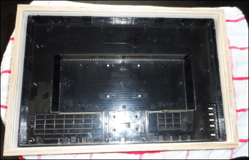
- At this stage, it would also be useful to mark the position of the hole that will allow power and video cables to reach the monitor. This hole should be at least 25 mm in diameter so that it accommodates an IEC power connector.
- Once the holes are marked, you can now put the display assembly back into the rear plastic case.
- The display assembly is rarely fixed into the plastic housing by anything other than the fact that it is enclosed by. So, if we give enough force, the display panel and electronics enclosure behind the display panel will be removed.
- Once the holes in the back panel are marked, the panel can be removed and the holes drilled with the following steps:
- The four holes for the VESA mount can be drilled using a 4.5 mm drill bit.
- The 25 mm hole will have to be drilled with either a fairly powerful mains hand drill or, better, a drill press using a Forstner drill bit.
- Once the back panel has the required holes drilled in it, it is worth giving it a quick sand over by using a coarse grit sandpaper, just to tidy the edge left by the router and Forstner drill bit.
- Next, reattach the back panel onto the rest of the enclosure using the screw holes made previously.
- At this point, it is worth powering up the monitor and ensuring that the display is set to fairly high contrast and brightness settings in order to get the best image quality through the mirrored acrylic.
- Once this is done, feed the cables through the hole previously made for them. Line up the VESA mount with the holes drilled for them and screw the monitor into position.
If your monitor has buttons mounted on the front panel, you can simply place the PCB they are mounted on behind the monitor within the range of the cable through which they are connected to the monitor.
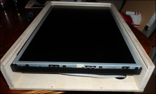
Note that if the monitor is too far back in the enclosure (that is, the display surface is more than 1 mm away from the slot for the mirror), then you may need to add some washers and spacers to the screws to move the monitor slightly forward, as shown in the following image:
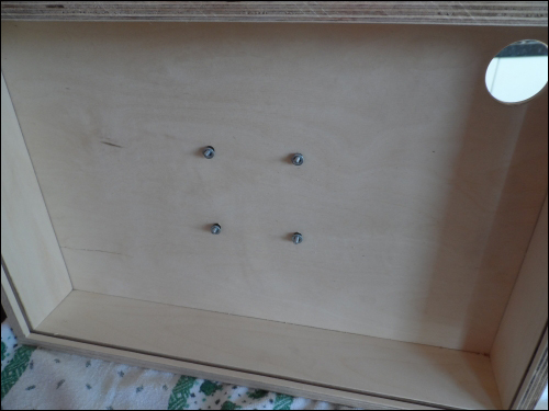
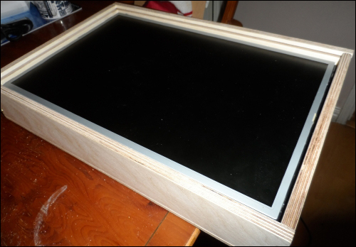
By this point the enclosure should look something like the following image:
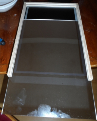
- The final step is to insert the mirrored acrylic panel into the slot cut for it. This can be easily done by removing one of the short side panels with the following steps:
- Firstly, remove the screws that hold the short panel in place on both the long side panels and the back panel and remove the panel.
- You should now be able to slide the mirrored acrylic panel into the enclosure easily.
- At this point, you may wish to power on the monitor once more to check whether the display settings leak any light through the mirror panel when the display is black. If so, turn the brightness down slightly.
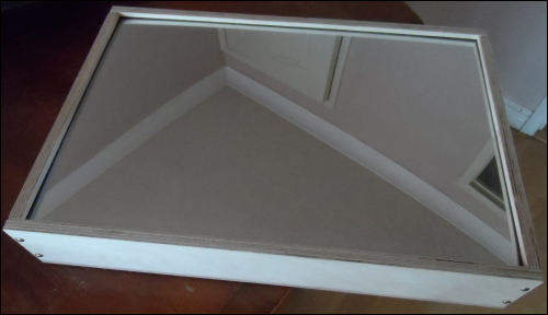
- The final step is to reattach the short side panel and the enclosure is complete.
- Firstly, remove the screws that hold the short panel in place on both the long side panels and the back panel and remove the panel.
Since the buttons on the monitor are no longer easily accessible from outside the enclosure, it is important to ensure that the monitor will automatically turn on when power is applied to it. This will be the method used to enable and disable the information display on the mirror.
If desired, hardware fittings can be used to make the mirror wall mountable. However, for now, we will use ours as a desk mounted mirror only. It is recommended that you place the mirror against a wall to ensure good stability, as its high center of gravity does make it more liable to fall over even if very little force is applied to it. If this is an issue, then you could use it in the landscape mode by changing the display rotation.
If you do not have access to the tools required to build the plywood enclosure (or would simply prefer a more modern-style mirror) then you can adapt an existing monitor into a mirror relatively simply without any tools. All that is required now is an adhesive.
You may wish to use a temporary adhesive, such as a clear tape or hot glue for this to ensure that the monitor can be reused if you decide to remove the mirror material. Although nothing is stopping you using something like a contact adhesive, such as Araldite, for a more permanent fitting.
- The first step to construct the display is to measure the size of the mirror material that will be needed. These are essentially the dimensions of the screen that is exposed on the inside of the plastic bezel around the side of the monitor (refer to the following image). Order the mirror material to be cut a few millimeters smaller to ensure that it will definitely fit within the inside of the bezel.
- Once you have the mirror material, you should find that it simply drops into the bezel with around 1 mm spared on each side.
- Next, using your adhesive of choice, fix the mirror material into the bezel of the monitor. It is important here to avoid getting adhesive of any type on the display surface, as this can damage the monitor.
Since the Pi is not part of the enclosure we have built, you may wish to keep the Pi in an external enclosure. There are many of these available at online retailers. One of my personal favorites is the Pibow range by Pimoroni (http://shop.pimoroni.com/products/pibow-raspberry-pi-case).