
The first thing you must do before getting the parts for the case machined is decide which video connector you will use. You can use either HDMI or composite video and 3.5 mm audio jacks. This will determine which side of the Pi is next to the side of the enclosure, since the two video outputs are on the opposite sides of the board and as such, there are differences between the designs of each enclosure.
For both types of enclosure, the files in the enclosure folder in the files for this project must be machined. There are two folders, hdmi and composite_video, that contain the parts specific to each video output type.
The parts needed for each type are shown in the following figure:
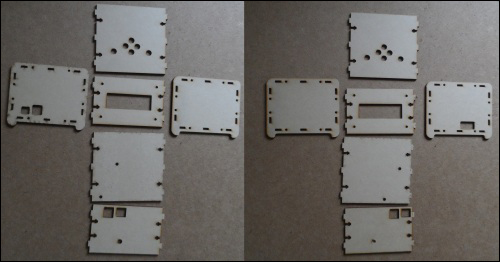
The two enclosure variants: composite video on the left and HDMI on the right
Once you have the parts you need for the enclosure type you have decided to build, it would be a good idea to remove any wiring already done so far to make the assembly process easier.
Once this is done, perform the following steps:
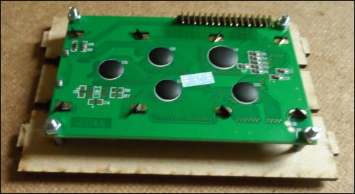
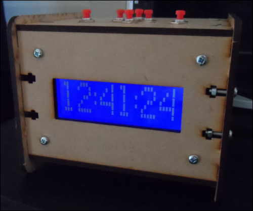
- Start by mounting the LCD into the front panel. This should be done with four M4 machine screws and nuts. Ensure that you do not over tighten the nuts and put excess strain on the PCB.
The front panel is symmetrical with the horizontal center of the LCD module, so it does not matter which side or which orientation the front panel is in when you mount the LCD. Do try to pick the side that is better looking.
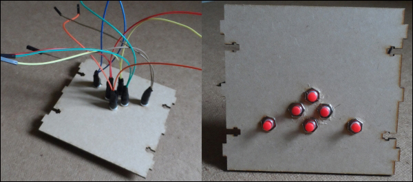
- Next, mount each of the push buttons in the top panel using the washers and nuts that came with the buttons, as shown in the following image:
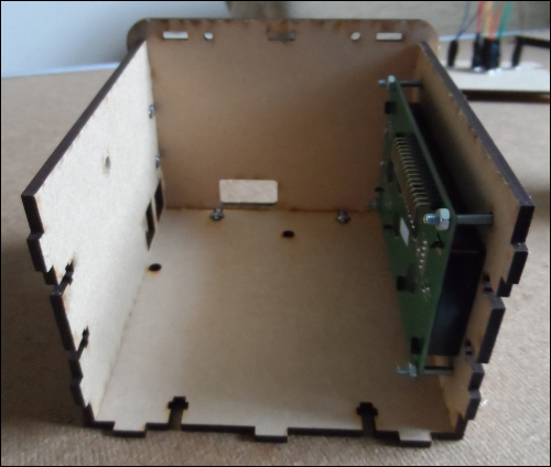
- Next, we can assemble the top, bottom, back, and side panels that will include the cutout for the video connector, that is, if you are building the composite video version of the enclosure, you will have the opposite side attached to what is shown in the following image:
- Around the edge, the middle panels connect to the side panels. Here, you will see a series of fittings similar to those shown in the following image. These require an M4 nut to be inserted into the slot and an M4 machine screw to be inserted through the hole in the side panel, as shown in the following image:
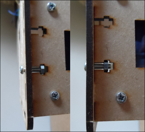
The screw fitting—before being tightened (left) and after being tightened (right)
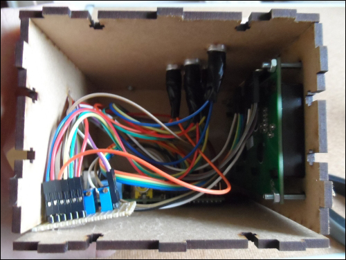
- Next, mount the Pi into the enclosure using two M4 machine screws through the bottom panel. Here, it is useful to use a stack of watchers to space the PCB apart from the bottom panel to help remove strain in the PCB. Before doing this, it is important to verify that the washers you intend to use are small enough to prevent causing a short with any exposed components at the bottom of the Pi.
This is also a good point to start rewiring the Pi, LCD, and the small board we made to control the LCD brightness and contrast.

- Next, we will rewire the buttons to the Pi as before and attach the top panel in the same way as the other three.
By this point, the media center wiring should be complete. Now, you can mount the DC barrel jack that will be used to power the Pi externally to the back panel using the nut and washer that was supplied with it.
- At this point, you are ready to attach the remaining side panel and give the media center a test before fastening the remaining screw fixings.
- If all seems to be good and both the LCD and buttons work as intended, you can go ahead and fasten the remaining side panel using the same screw fixings that were used for the other side.
Here, it is important to keep the enclosure tilted so that if one of the nuts falls out of the slot, it will fall outside of the enclosure rather than inside it.