
The RF network that will be used for the sensor nodes is provided by the RF24Network library (https://github.com/TMRh20/RF24Network). This allows RN nodes to be networked in a tree structure in which each node can have up to five child nodes, since each individual node can listen to up to six other nodes at once.
As such, the addresses for the nodes are octal and follow the structure, as shown in the following diagram, where 000 is always the base node, 001 is a child of the base node, 021 is a child node of 001, and so on:
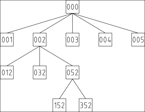
This allows a message to be passed to any node on the network by first transmitting it upwards through the tree until it reaches the first node that is a common path for both the sending and receiving node.
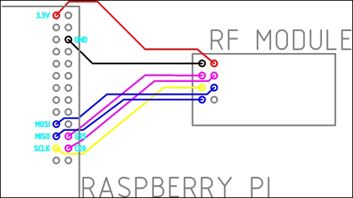
To set up the Pi as the base node for the RF network, we must first connect the RF module to the GPIO port and install the drivers that will allow us to receive messages send to it by using a Python script. To do this, perform the following steps:
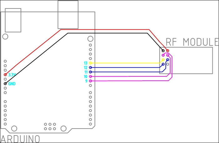
- First, start by wiring the module to the GPIO port using the following wiring diagram:
- Next, install the driver for the RF module. This is the driver that allows basic point-to-point communication using the RF modules:
sudo apt-get install libboost-python-dev git
git clone https://github.com/TMRh20/RF24.git
cd RF24
sudo make install
cd RPi/pyRF24
sudo python setup.py install
- Now that the driver is installed, return to the home directory:
cd - Next, we will install the RF network driver. This is the network layer that provides the tree network routing:
git clone https://github.com/TMRh20/RF24Network.git RFNetwork2
mv RFNetwork2/RPi/RFNetwork ~
cd RFNetwork
sudo make install
cd RF24Network2/RPi/pyRF24Network
sudo python setup.py install
- Once the two libraries are installed, you will need to copy the
BaseNode_RPi.pyscript from therf_networkdirectory in the files for this project to the home directory on the Pi. - Now that the drivers for both the module and the network layer are installed, we can test the base node script using the following command:
sudo python BaseNode_RPi.py localhost 1338
This should give an output similar to the following. If you see a repeating pattern in the configuration data or all the bits are set to the same value, then you may have an issue with the wiring between the RF module and the Pi.
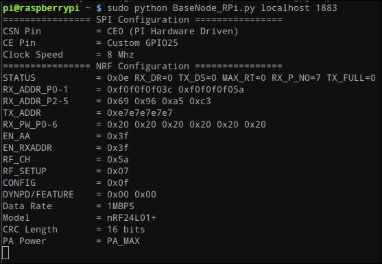
Assuming that the output of the script was similar to the previous screenshot (such that the values are not all 0x00 or 0xFF), we can go ahead and configure the base node script to start when the Pi boots. To do so, perform the following steps:
- Open the
rc.localfile innano:sudo nano /etc/rc.local - Add the following line to the end of the file, just before the
exit 0line:python /home/pi/BaseNode_RPi.py localhost 1883
This is shown in the following screenshot:

Once this is complete, reboot the Pi to run the base node and web application on boot. This completes the configuration that needs to be done on the Pi.
It's now time to program each of the RF nodes that will be used in the sensor network. We can program these using the code in the rf_network/SensorNode_Arduino directory in the files for this project and the Arduino IDE.
You should already have the Arduino IDE installed from when it was used in a previous chapter. However, we first need to download some additional libraries for the RF module:
- The two libraries needed can be downloaded from https://github.com/TMRh20/RF24 and https://github.com/TMRh20/RF24Network. You will see the Download ZIP option at the right-hand side bar of the website.
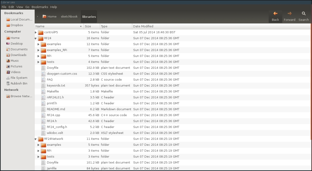
- Once these are downloaded, extract both the archives and place them into the
sketchbook/librariesdirectory. The sketchbook directory is where the Arduino IDE stores saved code files by default and where it searches for third-party libraries. By default, this folder is in your home directory.When doing this, ensure that the program used to unzip the archives does not create an additional directory (this is known to happen when you unzip them with Windows Explorer). The directory structure should be similar to that shown in the following screenshot:
- Next, we will connect an RF module to each Arduino that we will use as a sensor node. This should be done by following the next diagram and when the Arduino is not powered:
Next, using the following steps, program each Arduino by using the sensor node code based on the system structure diagram given earlier in this chapter:
- Connect the Arduino to your PC and open an unmodified version of the
SensorNode_Arduino.inocode in the Arduino IDE. - Change the
THIS_NODE_ADDRvariable to the address of the node you have connected. Note that having0at the start of the address is required, that is, if the address is 23, you must use023as the value. - Set the
NUM_SENSORSandsensorsvariables as described in the Interfacing sensors section.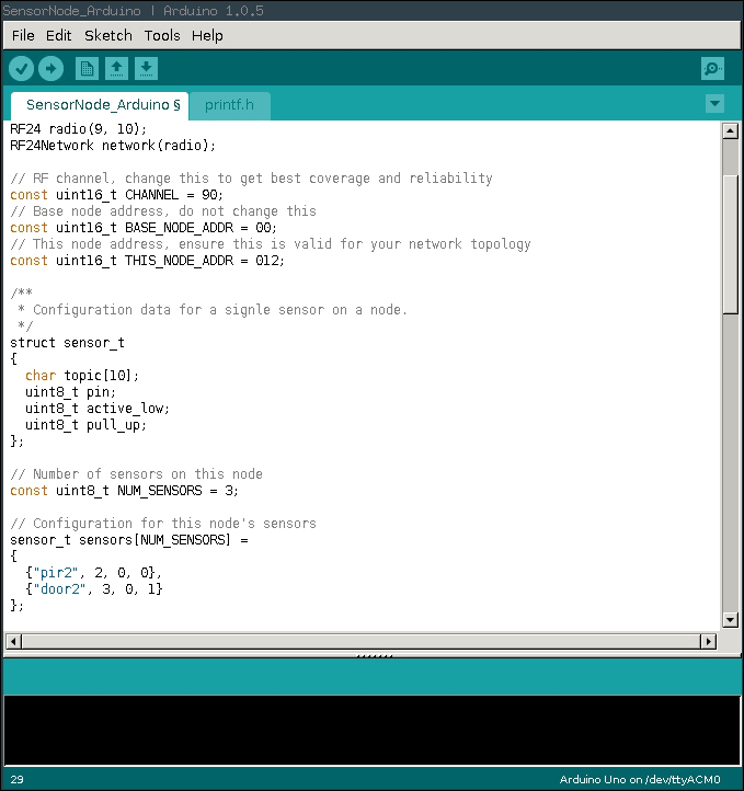
- If you program the nodes in order of their position away from the base node (for example, 002, 012, and 003), you will be able to test each node as you program it. This is as simple as opening the events page on the web application and verifying that new events show up for the sensor when it is changed. If this does not happen, refer to the Troubleshooting section.
- Assuming that the sensor node works as intended, you can now disconnect the node from your PC. Although, if you wish to keep testing additional nodes, you will need to power the node externally.
Once all the sensor nodes are programmed and tested, they can be installed in their intended positions. I found that Blu-Tack is a good temporary fix for the nodes that are to be placed above the doors.
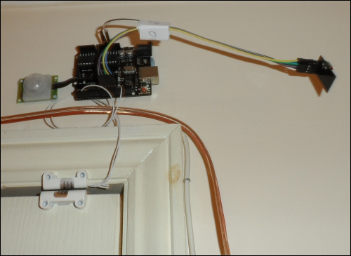
The sensor node with a door switch and PIR sensor installed above a door frame using Blu-Tack