
Since we are using a premade flight case as the base for our speaker system's enclosure, all we have to do is cut a single panel that will hold the speakers, volume control, and power switch on a panel that is exposed. We can do this by opening the case, thus hiding the Pi, battery, and electronics behind it.
To make this panel, we will use a 3 mm medium density fiberboard (MDF); this is a cheap material and is very easy to work with.
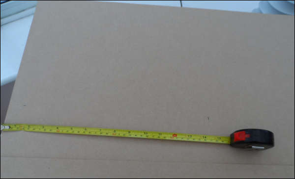
First, we will need to cut a square of MDF that is just smaller than the opening in the flight case. To do this, first measure the length and width of the inside of the flight case and mark this distance away from two edges of a sheet of MDF, as shown in the following image:
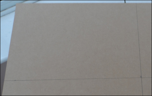
Next, take a try square and draw a line parallel to each edge in line with the markings in order to give an outline of where the square needs to be cut to get our panel as shown in the following figure.
Once this is done, we can take a jigsaw and cut along the lines to get the panel, which should be able to snugly fit in the opening of the flight case.
Now that we have the basic panel for the enclosure, we will cut the two speaker holes. Since different speakers are mounted in different ways, I assume that you are using the same speakers that are listed on the parts list here.
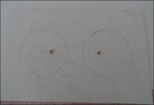
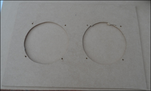
Mounting the speakers will first involve cutting a large hole into the sheet to set the speakers in and then drilling four smaller holes that are used to bolt the speaker to the panel. Fortunately, for the speakers, the large hole can be marked out easily by tracing around a CD.
Once you have the outline of the speaker positioned correctly, drill a 10 mm hole near the edge of each circle, as shown in the following image. This will allow us to get inside the circle with the jigsaw in order to cut a large hole in the panel.
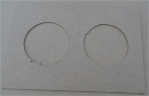
Once this is done, insert the blade of the jigsaw into the hole and cut around the outline of the circle for each speaker. It isn't vital that the holes are cut neatly or accurately, since the speaker will cover this edge when installed; however, it is important that the speaker sits flat when it is mounted on the cutout.
Next, we need to drill the mounting holes that will be used to bolt the speakers to the MDF panel; in this case, we will drill 4 mm holes and use M3 screws and nuts to mount the speakers.
First, mark the positions of each hole by placing the speaker into the hole and making a mark on the MDF through the hole in the speaker fascia (with a pencil, for example).
Next, drill a 4 mm hole in each marked position. It would be a good idea to check whether the holes line up with the speaker correctly by trial fitting it with just the screws; however, we will mount the speakers properly later.
Next, we need to drill a single hole large enough for the shaft of the volume control. The best place to position this is in between the speakers, but far away enough to leave room for the front plate. Once the position is marked out, drill the hole and remove any loose pieces of material.
The hole for the power switch is probably the most difficult since it is a square hole. For this, we will drill two 10 mm holes and use the jigsaw to make the two ends square and remove the material in between them.
The two holes should be around 15-20 mm apart. This should allow a snug fit of the switch once the full hole has been cut out using the jigsaw. In this case, since the edge of the cut may be more visible, it is a good idea to take a small amount of material off in each pass and to keep checking whether the switch fits neatly.
Now that all the mounting holes have been cut out of the panel, it is time to mount each component on the panel. We will start with the two speakers, which can be mounted by inserting the speaker into the large hole and fastening it in place using an M3 machine screw in each mounting hole with a corresponding washer and nut. To make the wiring neater, it is a good idea to have the terminals of each speaker facing the same direction. I recommend having them face the back of the flight case.
Next, the power switch can be fitted; this requires you to disconnect the connections to the amplifier terminal blocks first. Once disconnected, this is simply a case of feeding the wiring and fuse holder through the mounting hole and pushing the switch into the hole. Once in place, it should be kept securely in place by friction alone.
Next, the volume control can be mounted by pushing the threaded shaft through the hole drilled for it from the back of the MDF panel. Place the plastic front plate over the shaft on the front of the MDF panel and fasten it in place using the included nuts. The knob should then be pushed on, ensuring that the indicator lines up with the minimum indicator on the plastic front panel.
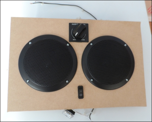
By this time, the front of the MDF panel should look similar to the following image:
All that is left to do now is mount the DC-DC converter and amplifiers to the back of the panel, reconnect, and tidy up the wiring.
Since the amplifier modules have mounting holes, I used these to thread some large cable ties through and fastened them to the two speakers. This allows a secure mounting of the amplifiers that does not need additional holes to be drilled in the MDF panel.
The DC-DC converter can be mounted anywhere on the MDF panel using any suitable adhesive. I would recommend hot glue as it allows fairly easy removal without risking damage to the converter, but you can also use double-sided tape.
The next step is to reconnect all the wiring that is currently disconnected. While doing so, it is a good idea to trim any wires that are excessively long so that each wire is just long enough to reach where it should connect to. This is mainly done just to make the wiring tidier.
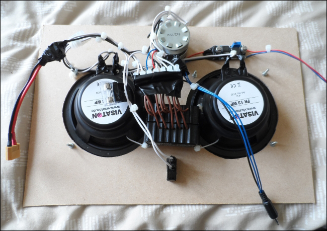
By now, the back should look as shown in the following image:
Assuming that you are using the same flight case that I used, there are two dividers included that make a perfect spacer to keep the MDF panel a good distance from the bottom of the flight case, the spacers should be placed around 40 mm from each side of the case.
All that is left to do now is reconnect the Pi and battery and give the system a test.