
The first thing we will do is set up the two pieces of hardware and verify that they are working correctly before moving on to the software.
The first (and the most important) piece of hardware we need is the camera board. Firstly, start by connecting the camera board to the Pi.
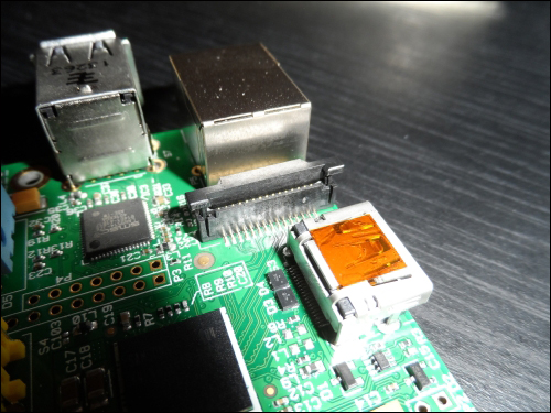
The camera is connected to the Pi via a 15-pin flat, flex ribbon cable, which can be physically connected to two connectors on the Pi. However, the connector it should be connected to is the one nearest to the Ethernet jack; the other connector is for display.
- To connect the cable first, lift the top retention clip on the connector, as shown in the following image:
- Insert the flat, flex cable with the silver contacts facing the HDMI port and the rigid, blue plastic part of the ribbon connector facing the Ethernet port on the Pi:
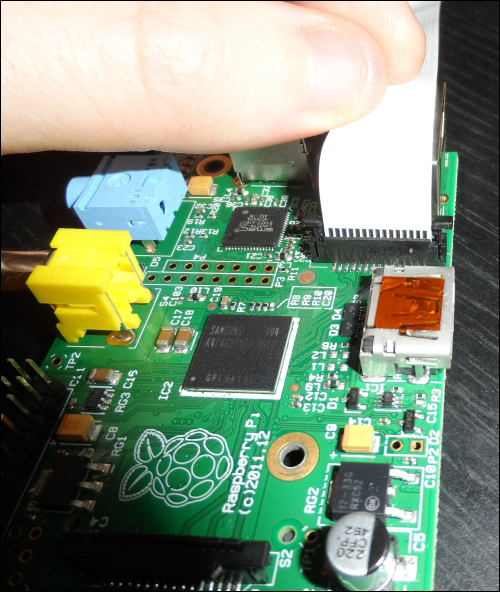
- Finally, press down the cable retention clip to secure the cable into the connector. If this is done correctly, the cable should be perpendicular to the printed circuit board (PCB) and should remain seated in the connector if you try to use a little force to pull it out:
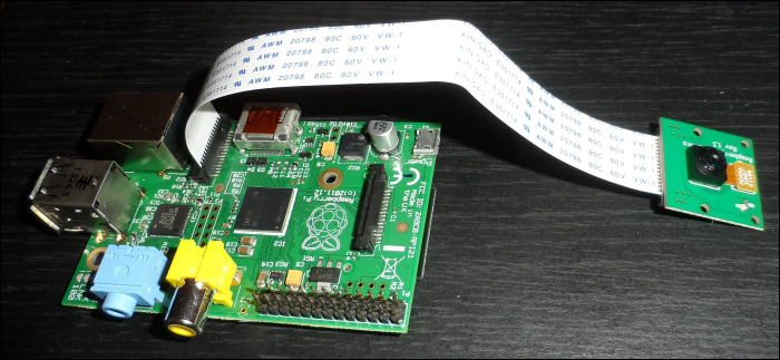
- Next, we will move on to set up the camera driver, libraries, and software within Raspbian.
Firstly, we need to enable support for the camera in the operating system itself by performing the following steps:
- This is done by the
raspi-configutility from a terminal (either locally or over SSH). Enter the following command:sudo raspi-configThis command will open the following configuration page:
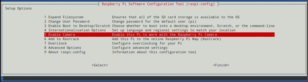
This will load the configuration utility. Scroll down to the Enable Camera option using the arrow keys and select it using Enter.
- Next, highlight Enable and select it using Enter:

Once this is done, you will be taken back to the main
raspi-configmenu. Exitraspi-config, and reboot the Pi to continue. - Next, we will look for any updates to the Pi kernel, as using an out-of-date kernel can sometimes cause issues with the low-level hardware, such as the camera module and GPIO. We also need to get a library that allows control of the camera from Python.
Both of these installations can be done with the following two commands:
sudo rpi-update
sudo apt-get install python-picamera
- Once this is complete, reboot the Pi using the following command:
sudo reboot - Next, we will test out the camera using the
python-picameralibrary we just installed.To do this, create a simple test script using
nano:nano canera_test.py - The following code will capture a still image after opening the preview for 5 seconds. Having the preview open before a capture is a good idea as this gives the camera time to adjust capture parameters of the environment:
import sys import time import picamera with picamera.PiCamera() as cam: cam.resolution = (1280, 1024) cam.start_preview() time.sleep(5) cam.capture(sys.argv[1]) cam.stop_preview() - Save the script using Ctrl + X and enter Y to confirm. Now, test it by using the following command:
python camera_test.py image.jpg - This will capture a single, still image and save it to
image.jpg. It is worth downloading the image using SFTP to verify that the camera is working properly.
Before connecting the GPS module to the Pi, there are a couple of important modifications that need to be made to the way the Pi boots up.
By default, Raspbian uses the on-board serial port on the GPIO header as a serial terminal for the Pi (this allows you to connect to the Pi and run commands in a similar way to SSH). However, this is of little use to us here and can interfere with the communication between the GPS module and the Pi if the serial terminal is left enabled. This can be disabled by modifying a couple of configuration files:
- First, start with:
sudo nano /boot/cmdline.txt - Here, you will need to remove any references to
ttyAMA0(the name for the on-board serial port). In my case, there was a single entry ofconsole=ttyAMA0,115200, which had to be removed. Once this is done, the file should look something like what is shown in the following screenshot: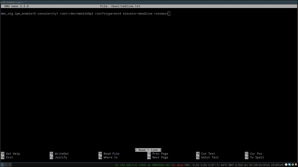
- Next, we need to stop the Pi by using the serial port for the TTY session. To do this, edit this file:
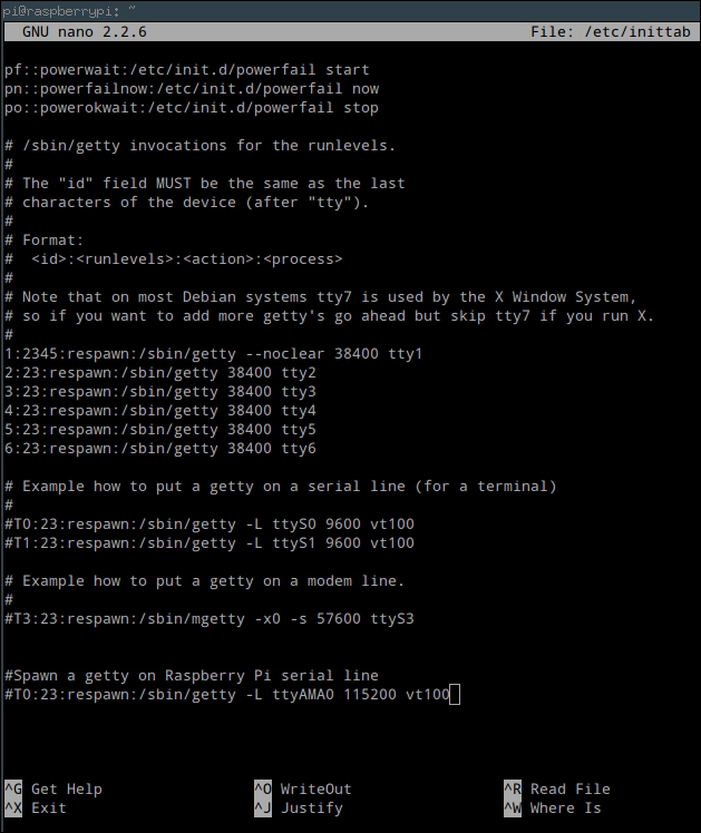
sudo nano /etc/inittab - Here, look for the following line and comment it out:
T0:23:respawn:/sbin/getty -L ttyAMA0 115200 vt100
Once this is done, the file should look like what is shown in the following screenshot:
- After both the files are changed, power down the Pi using the following command:
sudo shutdown -h now
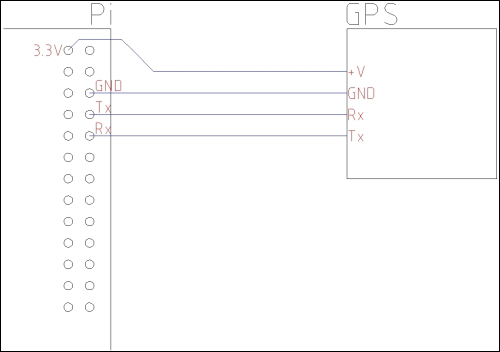
Next, we need to connect the GPS module to the Pi GPIO port. One important thing to note when you do this is that the GPS module must be able to run on 3.3 V or at least be able to use a 3.3 V logic level (such as the Adafruit module I am using here).
Next, connect the GPS module to the Pi, as shown in the following diagram. If you are using the Adafruit module, then all the pins are labeled on the PCB itself. For other modules, you may need to check the data sheet to find which pins to connect:
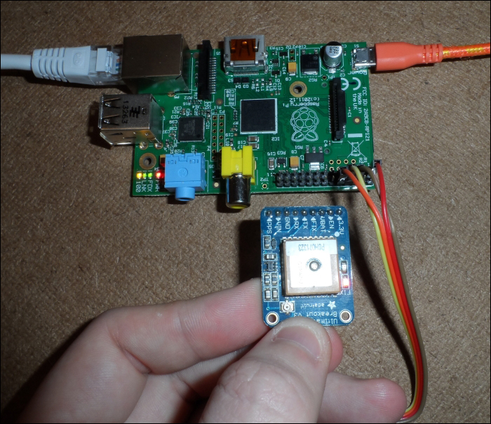
Once this is completed, the wiring to the GPS module should look similar to what is shown in the following image:
After the GPS module is connected and the Pi is powered up, we will install, configure, and test the driver and libraries that are needed to access the data that is sent to the Pi from the GPS module:
- Start by installing some required packages. Here,
gpsdis the daemon that managed data from GPS devices connected to a system,gpsd-clientscontains a client that we will use to test the GPS module, andpython-gpscontains the Python client forgpsd, which is used in the time-lapse capture application:sudo apt-get install gpsd gpsd-clients python-gps - Once they are installed, we need to configure
gpsdto work in the way we want. To do this, use the following command:sudo dpkg-reconfigure gpsd - This will open a configuration page similar to
raspi-config. First, you will be asked whether you wantgpsdto start on boot. Select Yes here: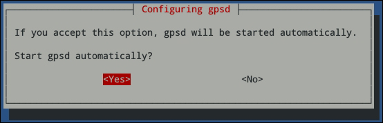
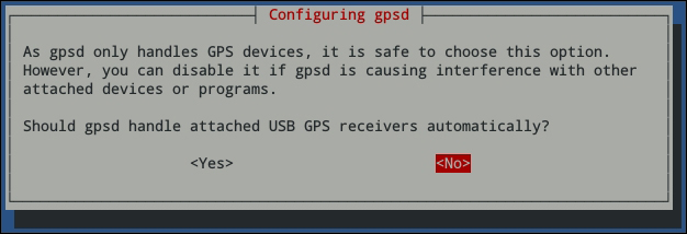
- Next, it will ask whether we are using USB GPS receivers. Since we are not using one, select No here:
- Next, it will ask for the device (that is, serial port) the GPS receiver is connected to. Since we are using the on-board serial port on the Pi GPIO header, enter
/dev/ttyAMA0here: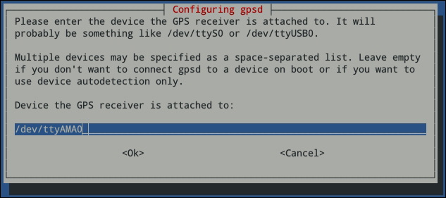
- Next, it will ask for any custom parameters to pass to
gpsd, when it is executed. Here, we will enter-n -G.-n, which tellsgpsdto poll the GPS module even before a client has requested any data (this has been known to cause problems with some applications) and-Gtellsgpsdto accept connections from devices other then the Pi itself (this is not really required, but is a good debugging tool):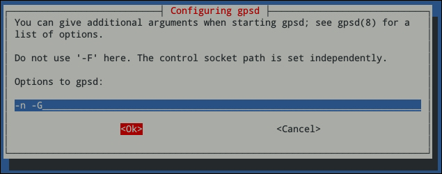
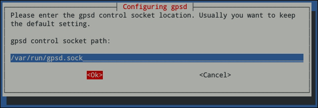
- Finally, you will be asked for the location of the control socket. The default value should be kept here so just select Ok:
- After the configuration is done, reboot the Pi and use the following command to test the configuration:
cgps -sThis should give output similar to what is shown in the following screenshot, if everything works:
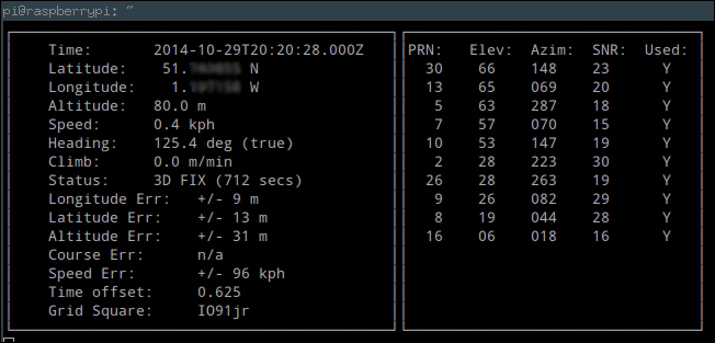
If the status indication reads NO FIX, then you may need to move the GPS module into an area with a clear view of the sky for testing. If cgps times out and exits, then gpsd has failed to communicate with your GPS module. Go back and double-check the configuration and wiring.