
Now that the note bottle assembly is built, it is time to build the electronics that will connect the servos to the Pi. This step is relatively simple, as all that you need to do is connect the Pi directly to the signal wire of the servos (usually yellow or white, sometimes orange) and provide power to the servos.
Since this project has the scope to use a lot of GPIO pins, we will use the Pi B+ for this project, which has an additional nine usable GPIO pins on its 40-pin header than on the older Pi model B's 26 pin header.
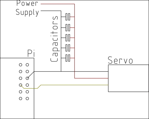
For reference, the circuit we will construct is laid out similar to the following diagram (note that for simplicity, only one servo is shown here):
The first step to create the electronic parts of this project is to build a power distribution board that can be connected to all the servos in order to receive power. This board is very similar to the one used for the servos on the robotic arm in Chapter 8, Remote-operated Robotic Arm. Perform the following steps to build a power distribution board:
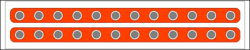
- Take a section of the prototyping board and 0.1-inch pin headers and solder them, as shown in the following diagram, such that there are two long strips of connected pins:
Once this is complete, you should have a board that looks similar to this:
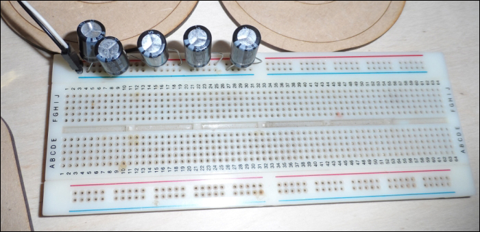
- If your power supply is rated for 3 A or less, you will most likely need to include a capacitor bank to ensure that there is a constant reliable power supply for the motors. This can be built by simply connecting the capacitors along with one of the power rails of a breadboard. Using two male-to-female jumper wires, connect this to the servo power distribution board.
Note
While building the capacitor bank, ensure that all the capacitors are wired in the correct way. There will be a light strip with several negative (-) symbols next to the leg that must be connected to the ground. This leg is also shorter than the positive leg.
If this type of capacitor is connected in the incorrect way in the circuit, then it can swell, leak, or explode.
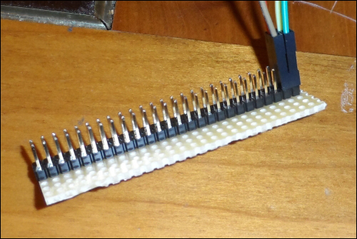
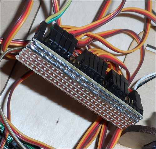
- Next, we will connect each of the servos to the power distribution board such that the signal pin is overhanging on the edge. Note that because of the width of the servo headers, you are better off if you connect them in sets of five, as shown in the following image:
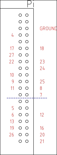
- Finally, we can connect the servo signal wires to the Pi. The following diagram shows the pins that are available on both the Pi model B (just the pins above the blue line) and the model B+ (the entire connector). In order to use the default configuration supplied with the code, you must have a note bottle on these pins: 4, 17, 18, 27, 22, 23, 24, 10, 9, 25, 11, 8, 7, and 5. The following diagram shows the GPIO pins available to connect the servos to and the common ground pin:
Once this is complete and all the bottles are in place, the finished setup should look something like this:
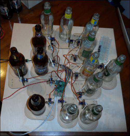
If you find that you cannot lay out each of the note bottles in a very suitable way due to the short cables on the servos, you can use some extension cables that give around another 30 cm of cable length. Such cables can be found at www.amazon.co.uk/Remote-Control-Servo-Extension-Cable/dp/B007SUKUXM.