
Now that we have the Maplin sensors and the LDR working properly, using the Arduino board, we can turn our focus to the remaining sensors that will measure temperature, humidity, and the barometric pressure.
For this, we will use DHT11 or DHT22 to measure the temperature and humidity and BMP180 to measure the barometric pressure. These devices can be interfaced directly to and powered from the GPIO port on the Pi.
DHT11 and DHT22 use a one-wire communication protocol to send data back to the Pi, which requires an additional 10 K (brown, black, and orange) resistor to be added between the data and 3.3 V pins on the sensor. The easiest way to do this is by mounting the DHT sensor, resistor, and a row of male pin headers on a small section of a stripboard, as shown in the following diagram:

Once this is complete, the board should look similar to the following image:
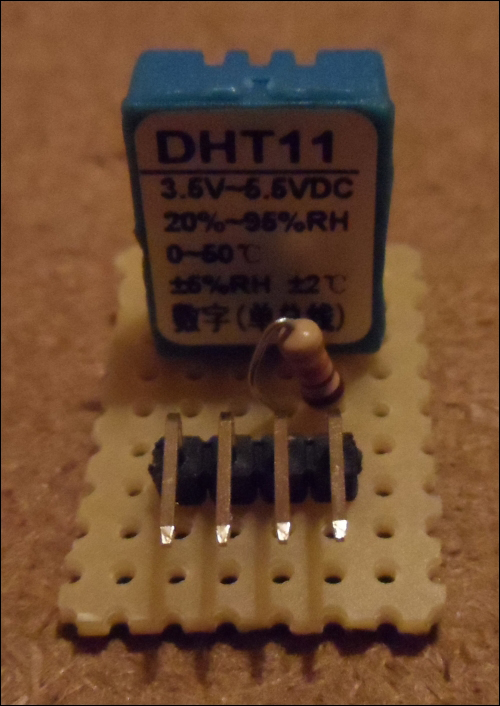
The copper tracks run vertically from the top of the preceding image to the bottom. As this is simply a task of adding a resistor across two tracks, there is no need to create any breaks in the copper tracks.
Now that we have a board for the DHT11/22 sensor, we can make the following connections to the Pi GPIO port by using female-to-female pin jumper wires:
- Pin 1 (the leftmost pin in the preceding image) to the Pi pin 6 (GND)
- Pin 2 should not be connected
- Pin 3 to the Pi pin 7 (GPIO 4)
- Pin 4 (the rightmost pin in the preceding image) to the Pi pin 1 (3.3 V)
Once the wiring is complete, we can now configure the software for the DHT11/22 sensor with the following steps:
- First, install some packages that will be needed to set up the drivers:
sudo apt-get install build-essential git - Next, clone the repository for the Adafruit driver and the BMP180 sensor:
git clone https://github.com/adafruit/Adafruit_Python_DHT.git - Change the directory to the repository we just cloned and run the setup script:
cd Adafruit_Python_DHT
sudo python setup.py install
- To ensure that the sensor is working correctly, change the directory to the
examplesdirectory and run the sample script. Note that if you're using the DHT22 sensor, you will need to change 11 to 22 in the following command:cd examples sudo ./AdafruitDHT.py 11/22 4
Assuming that everything went as it should, you should see an output similar to the following screenshot, with the readings taken from the sensor:
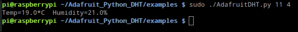
If this output is not produced, go back to the wiring and setup steps and ensure that the sensor is wired and configured correctly. It is worth double-checking the soldering on the stripboard to ensure that the sensor is wired with the correct pin and that there are no solder bridges between the tracks on the stripboard.
The BMP180 sensor comes almost ready to use and requires no external circuitry to connect it to the Pi, as it uses the very common and standardized I2C bus. The only assembly step to perform here is to solder the row of 0.1 inch pin headers on to the PCB. Be careful when you do this and do not get the iron too close to any of the components already mounted on the PCB.

Once the pins are in place, we can then wire the sensor to the Pi. This is done by making the following connections between the sensor PCB and the Pi GPIO header by using female-to-female pin jumper wires:
- VIN to the Pi pin 17 (3.3 V)
- GND to the Pi pin 25 (GND)
- SDA to the Pi pin 3 (I2C1 SDA)
- SCL to the Pi pin 5 (I2C1 SCL)
Once the wiring is complete, we can now configure the software for the BMP180 sensor:
- Edit the
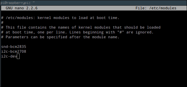
/etc/modulesfile to enable the kernel modules that will allow us to use the I2C interface bus on the GPIO header:sudo nano /etc/modules - Add the following lines to the file:
i2c-bcm2708
i2c-dev
The output should look like the following screenshot:
- Install some packages that will allow us to use the I2C bus from Python and a tool that we can use to detect which devices are currently connected to the bus:
sudo apt-get install i2c-tools python-smbus - Next, we need to check whether the
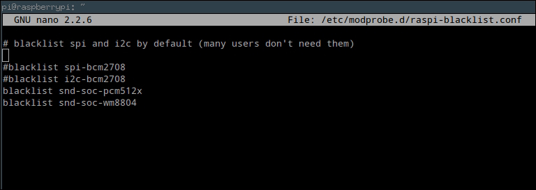
/etc/modprobe.d/raspi-blacklist.conffile exists, and if so, there are some lines that must be commented out. We can check whether it exists by opening the file innano; if it does not exist, thenanoeditor window will be empty:sudo nano /etc/modprobe.d/raspi-blacklist.conf - If the file is empty, you can skip the next step, otherwise, comment out the following lines:
blacklist spi-bcm2708
blacklist i2c-bcm2708
The file should look similar to the following screenshot:
- At this point, we need to reboot the Pi to load the new drivers:
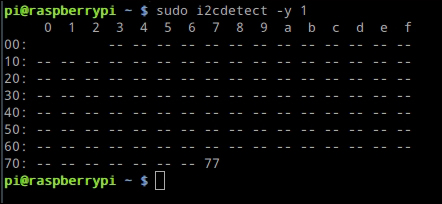
sudo reboot - Once the Pi reboots, use the following command to check whether the BMP180 sensor has been detected by the Pi correctly:
sudo i2cdetect -y 1If so, you should see an output similar to the following screenshot:
- Assuming that the device is now being detected correctly on the I2C bus, we can clone the repository for the driver that will interface with it over the bus with the following command:
git clone https://github.com/adafruit/Adafruit_Python_BMP.git - Change to the directory for the driver we just downloaded and run the setup script:
cd Adafruit_Python_BMP
sudo python setup.py install
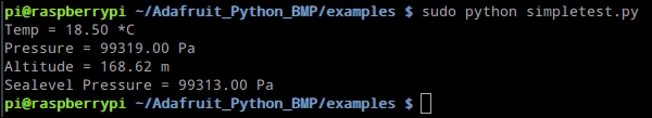
- To ensure that the driver is communicating with the sensor correctly, change to the
examplesdirectory and run the example Python script:cd examples sudo python simpletest.py
This should give an output similar to the following screenshot with the readings taken from the sensor:
If you did not get this output, then you may need to double-check the wiring between the sensor and Pi. If that looks OK, then it is worth rebooting the Pi and trying again.