Next, we will deploy the web application that will allow us to control the arm and chassis remotely and view the video stream from the Pi camera. Since this web application is also built using the Flask framework, the process of deploying it will again be similar to that used in the previous chapters.
Before we start, be sure to copy the config_files and robot_arm_webapp directories from the project files to the /home/pi directory on the Pi:
- First, we will install the required packages and libraries, including the RPIO Python library used to control the GPIO pins from Python:
sudo apt-get update
sudo apt-get upgrade
sudo apt-get install python-pip git python-dev gunicorn supervisor nginx
sudo pip install RPIO
- Next, download and install the Flask framework:
git clone https://github.com/mitsuhiko/flask.git
cd flask
sudo python setup.py install
cd
- Now, copy the Nginx configuration and perform the configuration self-test:
sudo cp config_files/nginx/robot_arm.conf /etc/nginx/sites-available/robot_arm.conf
sudo ln -s /etc/nginx/sites-available/robot_arm.conf /etc/nginx/sites-enabled/
sudo rm /etc/nginx/sites-enabled/default
sudo nginx -t
sudo service nginx restart
- Copy the supervisor configuration and tell the supervisor to reread the configuration files:
sudo cp config_files/supervisor/robot_arm_webapp.conf /etc/supervisor/conf.d/robot_arm_webapp.conf
sudo supervisorctl reread
- Copy the web application configuration file to the home directory. This defines the calibration settings for the servo positions and the GPIO pins each device is connected to. The GPIO settings should not be changed if the electronics were built by following the wiring diagram. We will look at the calibration values in greater detail later in this chapter. However, it would be useful to open the file and be familiar with the options that are available there.
sudo cp config_files/robot_arm.conf ~
nano ~/robot_arm.conf
- Finally, tell the supervisor to start the web application:
sudo supervisorctl update
sudo supervisorctl start robot_arm_webappp
Now that the web application has been deployed, we can test the electronics and camera streaming through the web application.
The main page of the web application shows the movement controls for the chassis and piArm:
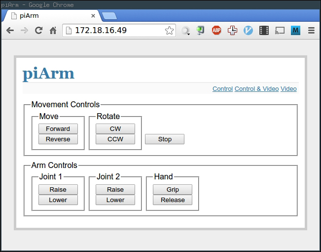
- First, test the movement controls and ensure that both the motors rotate in the same direction when you select Forward and in the opposite direction when you select Reverse.
- Next, ensure that the arm controls move the servos correctly. For Joint 2 and Hand, a single servo should move and for Joint 1, two servos should move in the opposite direction.
The video page (accessed using the Video link in the top-right corner of the web application) shows the live video stream from the Pi camera module. Below the stream, there is a link to the camera settings page provided by the streaming server. Note that there is no link back to the web application from the camera settings page, so you must navigate back to it manually after following this link.
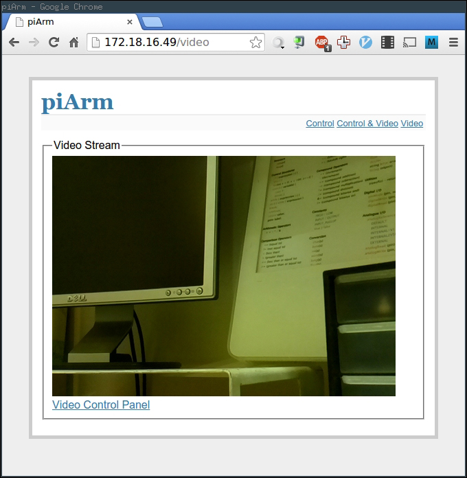
There is also a page that shows both the video stream and controls accessed using the Control & Video link in the top-right corner of the web application.

Now that the electronics are assembled, it is time to assemble the robotic arm and chassis. Firstly, we will go over what parts are needed to construct the robot.
In the cad directory in the project files, there are several DXF files for parts that are needed; the following is a list of all the parts that are needed to construct the robot:
- 1 x
Arm1_Main.dxf - 2 x
Arm1_ServMount.dxf - 1 x
Arm2_Main.dxf - 2 x
Wheel.dxf - 1 x
Spacers.dxf - 1 x
CameraMount.dxf - 1 x
Claw_ServoAttachment.dxf - 1 x
BaseLayer.dxf
Once all of the parts are machined, we can start the assembly:
- First, we need to attach the two geared motors and castor to the chassis base. This is done using four M3 screws and nuts for each motor and four M4 screws and nuts for the castor.
- Next, we can attach the relay board and the Pi to the chassis base using M3 screws and nuts as well as two of the spacers between the chassis base and PCBs.
- Next, we will attach the claw attachment to one of the servos, which will be mounted at the end of the second arm assembly. First, use one of the plastic attachments supplied with the servo to manually move the servo to half of its travel (this is to allow plenty of travel on either side of the current position for the calibration step later on).
- Once the servo shaft is in the correct position, we can remove the plastic attachment and attach the MDF claw attachment. This is done by pushing the servo shaft into the hole in the center of the circle. This will take some force, but will ensure that the MDF has a good grip of the servo shaft.
- Once the claw attachment has been attached to the shaft, use an M3 washer and the screw that came with the servos to fasten the attachment onto the servo shaft using the tapped thread at the end of the servo shaft.
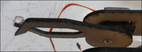
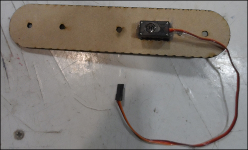
- Next, we will attach the servo to the arm 2 section; this is done by first threading the cable through the square cutout in one of the arm sections and using some hot glue to fix the servo into the cutout, as shown in the following image:
- Next, we need to cut six 50 mm lengths of M4 threaded bar, which will later be used to assemble the two arm sections.
- Next, we will assemble the upper arm assembly. Start by assembling the two sections of the upper arm by using two sections of the M4 bar in the first two holes nearest to the claw and space the gap using nine of the MDF spacers.
- Insert a section of the M4 threaded bar through the two holes at the end of the upper arm section; this will be used to connect to the servo, which will move the upper arm section.
- Next, we will attach the servo that will move the upper arm section to the lower arm section; again, the servo must first be set to 50 percent of its travel before you do this.
- Now, attach a single arm to the servo and screw it onto the servo shaft.
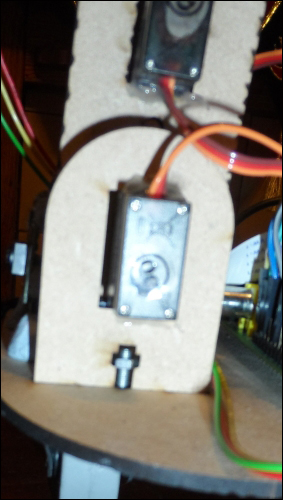
- Attach the servo onto the lower arm panel in the same way as was done with the previous servo, as shown in the following image:
- Next, we will take the remaining two servos and attach them to the two mounting brackets that are attached to the chassis base. These servos should both be set to 50 percent travel and aligned such that one servo is in the top-right corner of the cutout and the other is in the top-left corner. This is to ensure that the shafts have the best chance of lining up when they are attached to the chassis base.
- Next, the two lower arm panels must be attached to the two servos. This is done by pressing the shaft into the holes in the lower end of the arm panels and fastening the shaft with M3 washers and the screws supplied with the servos.

- Now, the lower arm assembly can be assembled in the similar way to the upper-arm section by fastening the two panels together using two of the M4 threaded bar sections and eleven of the MDF spacers.
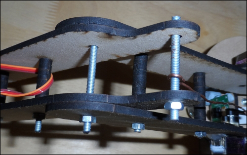
- The upper and lower arm sections can now be joined using a section of the M4 threaded bar, as shown in the following image. Note that this should be a fairly loose fastening to reduce the friction in this joint and therefore reduce the load on the servo.
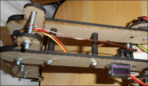
- Now, we can attach the entire arm assembly to the chassis base by using an M3 screw on each of the servo brackets, as shown in the following image:
- Now, we can connect the servo mounted in the lower-arm section to the bar across the upper-arm section using a piece of rigid copper wire. This should be attached to get the desired field of movement on the upper-arm section, which can be measured by manually moving the servo arm.
- The final step of the assembly is to attach the camera to the mounting bracket; the camera should first be disconnected to feed the flat, flex cable through the slot at the bottom of the bracket, as shown in the following image:
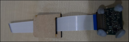
- Next, attach the camera to the bracket by using small sections of Blu-Tack (this allows us to adjust the angle of the camera to the optimal angle) and place the camera attachment into the slot in the chassis base.
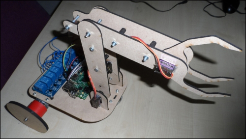
Once fully assembled, the robot should look something like what is shown in the following image: