
CHAPTER 8
Networks and Networking in Healthcare
Roman Mateyko
In this chapter, you will learn how to
• Explain how telecommunications networks are evolving with the advent of the Internet
• Describe key data networking concepts
• Describe the functions a data network performs using the OSI model of communications
• Describe how data flows in a wired or wireless network
• Describe HL7 and its use in transmitting healthcare data
This chapter is a brief tour through the topic of data networks and their use in healthcare. The topic of data networks is broad, deep, and constantly evolving. Many books have been written about data networks, so the best that a single chapter on the topic can do is give you an appreciation of key concepts, components, and approaches associated with data networks.
Telecommunications and Healthcare
The topic of data networks falls under the more general area of data communications. Data communications has roots in both telecommunications and computer science. Telecommunications is a broad topic area with relevance to healthcare. Doctors, nurses, and patients have been using telephones and telephone networks to talk to each other since the beginning of telephone service. Ambulances have used radio networks to communicate to hospitals to inform them of the state of patients in their care. Television networks have been used to inform citizens about the status of epidemics. The Internet and wireless networks of tomorrow have the potential to radically change the way healthcare is delivered.
From Voice to Data Networks and the Global Internet
For most of the past century, telecommunication was characterized by the emergence of special-purpose networks. First came the telegraph, which used a series of dots and dashes to communicate. Then came the voice network, which for most of the twentieth century was the truly global network. It consisted of end devices—telephones—that were attached by wire to a central office switch. Telephone systems were owned and operated by telephone companies. The voice network was engineered to transport voice conversations. Then came radio networks, which eliminated the need to run wire, made it possible to broadcast information to the masses, and made it possible to communicate with an ambulance rushing a patient to a hospital. Radio networks were then followed by television broadcast networks, which added the dimension of moving images to sound transmission. These networks had television sets as end devices connected to a cable head end. In the last third of the twentieth century, data networks emerged. Some were public, and some were private. They were controlled by enterprises, academic institutions, governments, and common carriers, and these networks transported data. Finally, cellular networks appeared. They made it possible for subscribers to place a voice call to anybody, anywhere and anytime, and then to check their e-mail on handheld devices such as the iPhone. Each of these networks had a specific function, but they presented a challenge to the providers of those networks in that they were independent networks, created especially for the traffic they carried and costly to manage on an individual basis.
The holy grail of the telecommunications industry has been the integration of these different networks into one. This has been attempted a number of times in the context of new technologies such as the Integrated Services Digital Network (ISDN) in the 1980s and then the Broadband Integrated Services Digital Network (BISDN) in the early 1990s; neither succeeded in totality. But then the Internet emerged to become the global network. Technological advances in the last 20 years have made it possible to carry data, voice, and video traffic over the Internet and over networks based on Internet technologies. It looks like the Internet will be the single network that carries it all.
Today different networks exist in the typical hospital setting: voice networks, pager networks, Wi-Fi networks, hardwired local area networks (LANs), ambulance radio networks, Bluetooth body monitoring networks, the Internet, and cellular networks. Each network has to be considered individually when it comes to planning, implementing, and operating, and these networks have to interoperate, which is sometimes a technical challenge. Healthcare will benefit greatly when the business needs that these separate networks fulfill can be accomplished using the Internet.
A single chapter cannot do the topic of data networks justice. However, since convergence will one day mean that Internet-type networks will carry all types of traffic (data, voice, and image) and interconnect all types of devices, then the focus of this chapter on Internet-type networks will give you the fundamentals you need to understand communications in the healthcare setting.
Data Communications Concepts
This section deals with the fundamental communications concepts that are key to understanding why healthcare networks are built the way they are and how they work.
Connectivity: The Geometrical Nature of Networks
Data networks make it possible for people or machines to communicate with each other, and these networks do it in the most efficient way possible. This efficiency is achieved by using technology and by making intelligent trade-offs.
Figure 8-1 shows how the number of connections increases as the number of endpoints of a network grows. The relationship is geometric (~n2/2). What this tells you is that it takes a lot of connections to make sure that many people or things can talk to each other in a network. And if you think about it, the maximum number of simultaneous conversations that you can have is n/2. (If you have an odd number of end points, then it is (n – 1)/2, which means in the case of an even number of connections that n2/2 – n connections are dormant.) If you were to use copper wires to connect these endpoints, you would be wasting a lot of copper, and that was what happened in the early days of telephony until innovations such as the switchboard and telephone switch were invented.

Figure 8-1 The connectivity problem
Figure 8-2 shows what happens when humans apply technology. The many connections are replaced with N connections into a box or piece of technology that magically ensures each end node can talk to any other end node. At one point in time, in voice networks, the stuff in the box was a set of relays and gears that connected one telephone to another, and the box was called a mechanical central office switch. Today the stuff is a special-purpose computer built of silicon chips running a software program called a router, or switch, that routes messages from one end node to another or to a network of these devices, also called the Internet, that routes messages globally. The efficiency that the technology in the box provides is traded off against the possibility that if too many messages are being sent through this box or combinations of boxes, some of them will be dropped; thus, the system has limited capacity, and that limited capacity is usually statistical in nature.
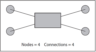
Figure 8-2 Technology applied to the connectivity problem
Exercise 8-1: Plotting Connectivity
Plot the equation n × (n – 1)/2 in a spreadsheet to see how the number of connections increases and compare the two approaches.
1. In column A of the spreadsheet, put the numbers 1–25.
2. In column B, put the equation n × (n – 1)/2.
3. In column C, put the equation n/2. Chart these to see the relationship. You can either ignore the odd numbers or use the equation (n – 1)/2.
Communication Models
Data networks originated as the need for computers to exchange information arose. In the case of the early Internet, universities needed to interconnect their computers to share research data. In the case of private data networks built by corporations and healthcare organizations in the latter part of the past century, these organizations needed a way to interconnect computers and users to computers supplied to them by computer manufacturers such as International Business Machines (IBM) and Digital Equipment Corporation (DEC). These computer manufacturers developed their own data network technologies and sold them alongside their computers. The problem occurred when information had to be shared across two or more data networks that were based on different computer manufacturers’ technology. For example, two hospitals, each having data networks based on different computer manufacturers’ technology, needing to exchange patient data would either have to somehow custom interconnect their networks or have to perform the exchange manually.
The computer community recognized this as a problem and developed two models of computer communications to solve it: the Open Systems Interconnect (OSI) seven-layer model (also called the OSI stack) and the Internet five-layer model. Both models define a set of standards that describe the functions of modern data communication systems. The OSI model, though widely accepted as a product of the International Standards Organization (ISO) standardization process, was never fully implemented because of the popular emergence of the Internet. The OSI model is used today in a theoretical way and is part of jargon used by network professionals. The Internet model is implemented by the global Internet and by networks based on Internet technologies.1 Figure 8-3 shows the two models side by side.

Figure 8-3 Comparison of OSI and Internet communications models
In both models, data in digital form (binary 1s and 0s) sent from an application residing in a transmitting device is passed down from the topmost layer—the application layer, which is the layer that interacts with a human—and is then encapsulated with control information from the layer below it until it reaches the physical layer where the binary 1s and 0s are turned into a physical representation—a pulse of light or electricity. Other than the physical layer, the functions of the other six layers are implemented in software. This process is then performed in reverse in a receiving device until it gets to the human at the application layer at the other end. In the model, the layer below performs a service to the layer above it. Each layer in the transmitter is said to have a virtual connection with each layer in the receiver, other than the physical layer, which has a physical connection. What follows is a brief description of each layer.
Physical Layer
Layer 1, or the physical layer, is responsible for converting the logical 1s and 0s coming from layer 2 into some type of physical signal such as a burst of electrons (voltages) or photons (light pulses).
Data Link Layer
Layer 2, or the data link layer, is responsible for controlling when a device should transmit (also known as media access), delimiting the message boundaries of the continuous string of 1s and 0s coming from layer 1 into packets, and ensuring that the transmission is error free by detecting and sometimes correcting errors.
Network Layer
Layer 3, or the network layer, is responsible for routing messages along the best route possible by building routing tables and assigning network addresses to devices attached to the network.
Transport Layer
Layer 4, or the transport layer, is responsible for error checking; flow control; sequencing packets; establishing, maintaining, and terminating conversations; and packetizing larger messages into smaller messages.
Session Layer
Layer 5, or the session layer, is responsible for initiating, managing, and terminating a communication session; initiating any adjunct services such as logging onto devices, file transfer, or security; and recovering from transport layer interruptions.
Presentation Layer
Layer 6, or the presentation layer, is responsible for displaying, formatting, and editing inputs and outputs (from the application layer). This layer makes it possible to display the same data on different terminal types. This layer may also be responsible for encryption.
Application Layer
Layer 7, or the application layer, is the interface between the human using the network and the network. A suite of applications exist at this layer such as HTTP (also called the Web), e-mail, the Domain Name System (DNS), and File Transfer Protocol (FTP).
Communications Protocols
Communications protocols define messages, message formats, and the rules for exchanging those messages between computers and communication devices. Imagine two computers communicating with each other, and associated with each computer is the seven-layer OSI model. As mentioned, each layer in one computer communicates virtually with each layer in the other computer according to a communications protocol. Transmission control protocol/Internet protocol (TCP/IP) is the prime example of a communication protocol for modern computer and communication devices. It is the fundamental communication protocol of the Internet. It can also be used as a protocol in a private network such as an intranet.
Figure 8-4 shows the message format of a generic protocol data unit (PDU). A PDU is associated with a communications protocol. The information in the PDU is represented by 1s and 0s. Other than the physical layer, each layer in the OSI model has a PDU associated with it.
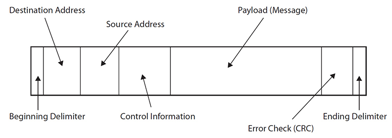
Figure 8-4 Generic PDU

NOTE Network professionals commonly call the data link PDU a frame and the network PDU a packet.
Each portion of the PDU is called a field and has a specific role. The two delimiters at each end of the PDU tell the system where the PDU starts and stops. Delimiters are analogous to capital letters and periods in a sentence. The destination address tells the system where the PDU is going, and the source address tells the system where the PDU has come from. The control information field carries in it codes that tell the system what to do. For example, one of those codes could signify that a transmitter wants to start a conversation with a receiver in a similar way that the alert tone on a cellular phone alerts a caller to an incoming call. The payload carries the message that is being transmitted. In the OSI model, the payload is usually the PDU from the layer above it. Examples of the types of messages that could be transmitted in the payload at the application layer in a healthcare setting include information about a patient’s medication, a transmission of a medical image, or real-time data coming from a patient-monitoring device such as a heart rate monitor. The payload could also contain HL7 information as described later in this chapter. Finally, the error check field is a type of quality control on the frame. The transmitter performs an algorithm that mathematically relates the information in the transmitted PDU to the error check field. The receiver performs that algorithm on the received PDU and then checks to see whether the value it calculated is the same as that sent in the error check field. If it is not, the same PDU is said to be in error, and some type of error correction is invoked such as retransmitting the PDU. A cyclic redundancy check (CRC), the specific error check depicted in Figure 8-4, is one such type of error check, whereby PDU has a short check value attached that is checked by the receiving system.
Data and Signals
In computer systems, information and data are represented as 1s and 0s; this is a logical representation. This is also true of all the layers of the OSI model except for the physical layer. At the physical layer, the logical 1s and 0s become something that is real or physical, such as a burst of electrons or photons. The presence or absence of these bursts can signify a 1 or a 0. A chart of the amplitude or power of these bursts over time is referred to as a signal.
Figure 8-5 shows two signal types. The first is a sine wave, and the second is a pulse signal; 1s and 0s can be encoded in sine waves by varying amplitude, frequency, and phase. In pulse signals, a 1 can be represented by the presence or absence of a pulse.

Figure 8-5 Examples of signals
Information is transmitted through a network when these signals representing 1s and 0s travel through wires, fibers, and by radio propagation; each is considered a different transmission media. Each type of media has its own physical characteristics that affect those signals. Two such key characteristics are susceptibility to noise and maximum capacity, also called bandwidth.
Susceptibility to noise relates to how easily external signals not associated with the transmitted signal can get induced into the media and thus distort the transmitted signal. This distortion leads to errors. In the case of the pulse signal, there may be a spike of noise that causes an empty spot where there is no signal to look like a pulse. The receiver then interprets that noise burst as a 1, which is not what the receiver sent and is therefore an error. Maximum capacity relates to how much information transmission media can carry. For example, fiber-optic media can carry much more information than can copper media, and a coaxial cable can carry more information than a 26-gauge telephone cable.
Digitization
Digitization is the process of representing something like an image or sound using discrete samples and then being able to reconstruct it with a certain level of fidelity. Sampling of music and then storing those samples as binary digits on a plastic disc is how music is distributed using CDs. A similar thing is done with medical imaging associated with picture archival and communication systems. Binary digits or 1s and 0s are the same things that data networks transport. Given that images and voice signals can be sampled, those samples can be carried by data networks. This is how the Internet will become the single network carrying data, voice, and video traffic.
Throughput
A measure of how much data can be moved through a network successfully is called throughput. Throughput is measured in bits per second (bps). Usually people will use the term bandwidth and state it in terms of bits per second. In data networks, throughput can be affected by many things; one of those is the capacity of the transmission medium that places an upper limit on throughput. Another is the latency through the network. Latency is often the result of how digital signals are transmitted and processed by hardware and software in devices that make up the network. For example, as a packet encounters a router in its path across the network, it is read into the receive buffer of a router, analyzed, and put out onto the transmit buffer of that router. Every time this happens, a small delay is added to the packet’s journey. For a given amount of information transmitted, the longer it takes to transmit that information because of all these delays, the lower the throughput.
Addressing in Data Networks
If one device, the transmitter, wants to send information to another device, the receiver, it must know where to send that information. That means the receiver must have some type of identifier that distinguishes it from other, possibly similar receivers on the network. That identifier is usually called an address. In TCP/IP networks there are four types of addresses to consider.
MAC Addresses
Media Access Control (MAC) addresses exist at the data link layer. They are usually depicted as six groups of two hexadecimal numbers and are 48 bits long; see Figure 8-6. They exist in hardware, are assigned by device manufacturers, and are therefore fixed. They are also referred to as Ethernet addresses since they are what appear in the source address and destination address fields of Ethernet PDUs.
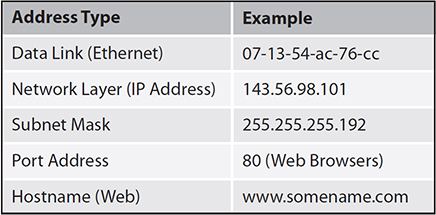
Figure 8-6 Sample network addresses
IP Addresses
IP addresses exist at the network layer. They are depicted as four groups of up to three decimal numbers separated by dots and are 32 bits long; see Figure 8-6. They exist in the software configuration of a network device and are either assigned manually by an administrator or assigned through a process called Dynamic Host Configuration Protocol (DHCP). These addresses are also broken down into the network part and host part, the delineation depending on the class of address.
Currently IP version 4 addresses exist in the global Internet. IP version 6 addresses are now being introduced and should supplant IP version 4 addresses in time. IP version 6 addresses contain 128 bits and therefore have a much greater address space than their IP version 4 counterparts. The world’s adoption of IP version 6 addresses will become critical because the IP version 4 address space is just about exhausted.
IP addresses are sometimes associated with subnet masks; see Figure 8-6. Subnet masks are a pattern of 1s and 0s that subdivide a range of IP addresses for routing and administrative purposes.
IP addresses are assigned to organizations by the Internet Corporation for Assigned Names and Numbers (ICANN).
IP addresses can be either dynamically assigned (i.e., each time a client logs in, a different IP address gets assigned) or static (i.e., a client has a fixed or constant IP address assigned by a network administrator). Servers using DHCP grant IP addresses to clients dynamically and for a limited time interval. DHCP is used to obtain configuration information, including an IP address. Two advantages of dynamic IP addressing are that there are fewer risks for security (because a new IP address is generated for each login), and that network configuration is automatic so it does not require an administrator. However, static IP addressing can be a more reliable way to ensure secure access to files stored on an organization’s network computers.
Transport Control Protocol (Layer 4) Port Addresses
Port addresses exist in layer 4 of the TCP/IP communications model. These port addresses are 16 bits long, and each port address is uniquely associated with an application. Port addresses 0 through 1023 are considered well-known ports, and the remaining port addresses are available for dynamic assignment. For example, web browsers use port address 80, and mail applications use port address 25. When an application is transmitting a message, it identifies to the TCP software which source port address it is sending from and which destination port address it is sending to. The TCP software then puts these in the source and destination fields of the layer 4 PDU it builds.1
Hostname
Hostname addresses exist at the application layer. They are usually depicted as a group of letters separated by dots. The letters usually form meaningful words such as www.google.com; see Figure 8-6. Hostnames reside in software in the host and also in Domain Name System servers. DNSs are databases that relate IP addresses to hostnames for the purpose of address resolution. DNSs form a domain name system; somewhat like the white pages, they relate human-friendly names to computer-understandable names, which are the addresses. ICANN manages the Internet domain system and authorizes private companies to assign domain names.
Address Resolution
Address resolution occurs at various levels when a sender is transmitting a message to a receiver. For example, when a user clicks a link in a web browser (the sender), a browser request message is sent to a web server (the receiver). That request is eventually placed into a packet at layer 3; however, that packet needs a destination IP address. That IP address is supplied by resolving that hostname through the Domain Name System to an associated IP address. That IP address is then placed in the destination field of the IP packet and sent into the network. At the other end, as that packet emerges on the LAN to which the web server (the receiver) is attached, the packet is placed in a data link frame, which needs a MAC destination address in order for it to arrive successfully. This MAC address is resolved to the IP address through the Address Resolution Protocol (ARP).
To determine which MAC address is associated with the destination IP address, the device sends a broadcast message to the LAN with the destination IP address in its payload. All the devices on the LAN receive that message, but only the device whose IP address matches replies. This reply has the MAC address of the replying device embedded in it. This MAC address is then used as the destination address for the data link frame, which transports the web request to the server.
End devices have caches that store these address resolutions temporarily. For example, a workstation will have a DNS cache and an ARP cache.
The World Wide Web as an Example of a Network Application
The World Wide Web (WWW) is one of the most popular network applications in use today and is increasingly used for transmitting healthcare data. It is an example of a client-server architecture where the client is a web browser such as Firefox and the server is a web server running a program such as Apache. The presentation and descriptive markup language that is used to generate web pages is HyperText Markup Language (HTML). The protocol used by the client to request a web page and by the server to respond to that request is HyperText Transfer Protocol (HTTP). The addressing mechanism that is used to locate a web page is called a universal resource locator (URL).
HTTP is a textual protocol that defines the rules and format for message exchange. For example, HTTP defines a request command that is used to request information from a server. The PDU for this command has a request line, a request header, and a request body. HTTP is an application protocol using the underlying services of TCP. When a link is clicked in a browser, it opens a TCP session with the host identified in the URL and sends that request via port 80 of the TCP PDU. The URL identifies the protocol (HTTP, FTP, or HTTPS) in use, the network location (host and port), and the path name to the data object on the server. The server then responds with an HTTP response. The PDU for a response is composed of a response status field, a response header, and the response body that contains the web page the client requested.2
PANs, LANs, MANs, and WANs
Data networks can be categorized according to physical extent, anywhere from centimeters to kilometers. The range of a given data network often dictates the type of underlying technology used and the design of the communications protocol that is needed. The way TCP/IP networks are designed is that the network and transport layers of TCP/IP are abstracted from the lower layers. Thus, TCP/IP rides on top of the two lowest layers and provides an end-to-end service for devices attached to the network.
PANs
Personal area networks (PANs) span the human body and the area near the human body. The communications technologies used here are typically Wi-Fi and Bluetooth, which are wireless technologies. The technology used includes network interface cards (NICs), which provide wireless interfaces for devices such as laptops, heart rate monitors, and tablets. The management of these networks usually falls to a healthcare unit in the organization whose staff members evaluate, select, purchase, deploy, and provide operational support for these devices.
LANs
Local area networks (LANs) span rooms or buildings. Wireless transmission and wired transmission are used. The communications technologies employed are typically Wi-Fi and Ethernet, also known as IEEE 802.3. The equipment includes NICs, hubs, switches, wireless access points, and file and print servers. Here again, the deployment model is usually local, with the organization’s staff evaluating, selecting, purchasing, deploying, and providing operational support for these devices.
MANs
Metropolitan area networks (MANs) are on the order of city blocks and urban areas. Again, wireless and wired technologies are used. Examples for physical transport technologies include 26-gauge copper telephone wire, cable plant, short-haul fiber optic, point-to-point microwave, and cellular networks. The communications technologies include Ethernet, ADSL, LTE, and WiMAX. Small ISPs, local carriers, and regional carriers tend to provide services at this level. Organizational staff manages contracts and service levels with suppliers of these services and interconnects their managed network infrastructure (PANs and LANs) to these networks.
WANs
Wide area networks (WANS) are on the order of large cities, provinces and states, and countries. Wireless and wired technologies are used as transport. Examples of transport technologies include point-to-point long-haul microwave, long-haul fiber systems, and satellites. Communications technologies include wide-area Ethernet over fiber, wavelength division multiplexing (WDM), and legacy carrier technologies such as Asynchronous Transfer Mode (ATM), Optical Carrier (OC), and Time Division Multiplexing (TDM). Regional and national carriers operate at this level. Organizational staff manages contracts and service levels with suppliers of this service and interconnects their managed network infrastructure to these networks.
The foregoing categories of networks can create a context for the reader to think about how healthcare information is communicated in the healthcare system. For example, monitoring devices on a patient can be continuously sending data via a PAN that connects to a device in the LAN. As the patient moves through a hospital, those monitoring devices connect and reconnect to various LANs that exist in that hospital. The application that analyzes that data may be running on a server located across the city from the hospital, and thus the data are gathered and then sent via a MAN to that server to be processed. The analysis of that real-time patient data may trigger a need for the patient to undergo a diagnosis by a specialist who is located in another city. That specialist and the patient would use a WAN to set up and use a video-conferencing system to perform that diagnosis.
How a Network Works
This section will describe how a typical TCP/IP network works. It will discuss application and network architectures and describe the components used to implement those architectures and the protocols used. It will also describe two examples of data transfer: one device communicating with another device on the same LAN and one device communicating with another device on another LAN across a WAN.1
Application Architectures
Two fundamental application architectures exist on a network: peer to peer and client server. In a peer-to-peer architecture, all devices on a network are equal and can perform the same function; there is no master. A peer-to-peer model works well when there are a limited number of users and has the advantage of being simple but the disadvantage of not being scalable. Also, the traffic pattern on peer-to-peer networks is random because any device may be talking to any other device. An example of a peer-to-peer application is instant messaging (IM). The first example presented in this section (see Figure 8-7) will follow the data flow between two workstations (W1 and W2) exchanging an IM message on LAN1.

Figure 8-7 How a network works
In client-server architecture, there are many clients and one server. That server performs a set of centralized functions for those clients. An example of client-server architecture is the Web. A web server has multiple web browsers, or clients, sending requests to it for web pages. It acts like a file server in that it is a central store of web pages. The client and server do not need to be on the same LAN; they just need to be connected to the network, as shown in Figure 8-7. A client-server model has the advantage of being able to scale and provide greater control but the disadvantage of unnecessary overhead for small scale. The second example presented in this section (also shown in Figure 8-7) will follow the data flow from a web browser to a web server. Here workstation W1, which is the client and is running a web browser, sends HTTP requests to server S2, the server, through LAN1 and across the WAN and then through to LAN2.
Network Architectures and Implementations
Network architectures vary according to the needs of the network. Networks used for healthcare purposes are different from networks used for business purposes. The architecture associated with Figure 8-7 is a simplified version of a WAN architecture, which is one that you may find in a healthcare setting.
Wide Area Network
The network in Figure 8-7 shows an implementation of a typical network architecture. There is a WAN that interconnects two LANs (LAN1 and LAN2) and then interconnects both to the Internet. A MAN or backbone network could serve the same function as the WAN in the diagram except that it would have a different geographic scope and use different technology. The WAN in Figure 8-7 consists of routers interconnected with communication circuits. Routers move messages (PDUs) according to a set of instructions that each has, called a routing table. Routing tables are dynamically built using routing protocols. These routing protocols are software programs that optimize the path that messages take by analyzing changes occurring in the network such as addition or deletion of networks or circuits, the utilization of circuits, and latency across circuits. Common routing protocols include Routing Internet Protocol (RIP) and Open Shortest Path First (OSPF). Routers are said to implement layers 1 to 3 of the OSI stack.
There are two more connections pictured in Figure 8-7, one to the Internet and one to a domain name server. Most modern networks connect to the Internet, and they usually do this using a special routing protocol called Border Gateway Protocol, whose job it is to make the rest of the Internet aware of the existence of the network by advertising its IP addresses. A firewall is also positioned between the Internet and the network. The firewall protects the network by filtering out unwanted traffic. The job of the domain name server is to resolve hostnames to IP addresses for this network.
NOTE Domain name servers are part of a globally interconnected hierarchical network that stores and distributes all hostname and IP address pairs.
Local Area Network
The purpose of a LAN is to interconnect a set of devices that are within physical proximity. A LAN makes it possible for users to share resources such as print, file, and fax servers. Attached to the WAN in Figure 8-7 are two LANs depicting two different architectures. LAN1 shows a bus architecture, and LAN2 shows a star architecture. These are physical architectures. The bus architecture of LAN1 is rarely used today. This architecture is implemented using a single coax cable that attaches to each device. LAN2, the physical star, where wires spread out from a central switch to all devices, is the way most LAN topologies are implemented today. Also attached to router R2, via the central switch, is a wireless access point, which shows how a wireless network could overlay a wired network.
From a network perspective, LANs are seen as broadcast domains where broadcasts of layer 2 PDUs or frames are generated by one device wanting to communicate with another device on the LAN. Although LAN1 and LAN2 differ at the physical layer, they function similarly at the data link layer. Broadcasts are characteristic of most LAN protocols and in particular of the widely adopted Ethernet protocol (802.3), which uses Carrier Sense Multiple Access with Collision Detection (CSMA/CD). In Ethernet, several devices are connected to a common infrastructure such as a shared coaxial cable or the backplane of a hub or switch. If one device wants to transmit to another device, it enters the MAC address of that device in a frame and then transmits that frame bit by bit onto the communications medium. All devices receive that broadcast frame, but only the device to which it is addressed recognizes it and then “reads” it in; other devices on the LAN ignore the broadcast. Because the transmitter is transmitting the frame, it also listens for any corrupted transmissions. If it detects one, it stops its own transmission and assumes another transmitter tried to transmit at the same time, which caused the collision. If there are no collisions, the receiver takes the frame and passes it up the OSI stack until it gets to the application layer where the message is delivered to the application. If there is a collision, each device that was trying to transmit simultaneously waits a different amount of time, the duration of which is determined randomly, and then retries its transmission.
Attachments to the LAN include end devices such as workstations, printers, servers, hubs, switches, and routers. To participate in the LAN, each device needs a network interface card and, in the case of a wired LAN, a cable attaching it to a hub or switch. End devices such as workstations and servers implement the complete OSI stack. They also run application layer software, which in the example is instant messaging client software. Alternatively, a user at W1 may be sending messages to a web server such as the server S2 in LAN2. Both these are done at the application layer. Those messages, however, are sent down the stack to each layer and to the physical layer where pulses of electricity or light emanate from the interface across the network, and then the inverse process occurs at W2 or at the server. In contrast, devices such as routers are said to communicate at the bottom three layers of the OSI stack. For example, W3 and the server will be communicating to the switch at layer 2 and below.
LANs provide the same function in a healthcare setting except in addition to workstations, servers, and printers, there could be health-specific devices, such as patient monitors, infusion pumps, and ventilators, attached to the LAN. Note that healthcare LANs need to be more robust and secure than most other types of LANs. They must be robust because missing patient data, especially real-time monitoring data, can affect patient safety. They must be secure because of the privacy requirements associated with patient data.3

TIP A service-level agreement (SLA) is a contract between an Information Technology (IT) service provider and a customer (for example, a hospital) that specifies what services the IT provider will furnish and almost always contains specific measures of the services to be provided. SLAs are commonly used for network service providers or ISPs, and contain such measures as percentage of time services will be available and how many simultaneous users can be served. Information Services (IS) departments in healthcare and other industries have adapted the SLA idea for internal, department-to-department agreements. An internal SLA specifies what the IS department’s responsibilities are, primarily around implementing, maintaining, and communicating the status of the IT services. In an internal SLA, the receiving department is also responsible for notifying the IS department (in a manner that is timely, complete, and accurate) of service failures or issues, and then assisting the IS department in the resolution of these failures or issues.
Device Configuration
Before an end device can start communicating, it must be configured. This configuration can happen either manually or automatically. The manual method involves having a network administrator configure the device or provide information for the user to do so. The automatic method involves using the Dynamic Host Configuration Protocol (DHCP). In either case, the following minimal information is configured on an end device: its IP address, a subnet mask, the IP address of its DNS server, and the IP address of the LAN gateway. In Figure 8-7, routers R1 and R2 are also called gateway routers because they are the gateway out of the LAN onto the bigger network. The address of the DNS server is needed to decode the hostname into an IP address. The subnet mask is used by the device to discern whether the destination address of a PDU it is sending resides on the local LAN. If not, then the PDU is forwarded to the gateway. The combination of IP address and subnet makes it possible for the device to determine whether it should be sending information to the gateway on the LAN for which it has the IP address.
NOTE The end device already knows its MAC address because it is assigned by the equipment manufacturer and exists in hardware.
Device Configuration in an End-to-End Network
The application layers of two devices that are communicating across a network are abstracted from that network. The complexity of the underlying network is hidden from them. The sending application and device usually determine the location of the destination application and device based on resolving a hostname to an IP address. Knowing that IP address and the port to which the application wants to connect (destination port address), the sending device software sets up a circuit that connects it virtually to the destination device. Then the reverse occurs, and a bidirectional communication channel is established between the two applications at both ends of the network. Neither device knows there may be LANs, WANs, switches, and routers in the path. Furthermore, TCP ensures a reliable transmission by having the transmitter resend PDUs that the receiver detects are in error. This mode of communication is also known as connection-oriented communications.
NOTE You should understand that this is a highly simplified explanation of the mechanism of transmission and error recovery; much detail has been omitted.
Ping is a useful network administration utility that can be used to check whether a host can be reached on an Internet Protocol (IP) network. It can also be used to assess how long it takes for messages to be sent from an originating host computer to a computer receiving the messages. Another useful TCP/IP utility is traceroute (known as tracert in Windows), a command-line tool that can be used to find the route of packets of information moving through a network to reach a host. By tracing the path of messages, traceroute/tracert can be used to test and troubleshoot problems in networking.
Use Case 8-1: A Device Communicating with Another Device on the Same LAN
In this example, device W1 will be sending an instant message to device W2 (see Figure 8-7). Let’s assume that W1 has already resolved W2’s IP address through a previous DNS request. (Note that W1 would have used the DNS’s IP address that is stored in its configuration to reach the DNS to resolve W2’s IP address.) Upon creation of the message by the user, the IM software tells the TCP layer which destination port address to use. The destination port field, source port field, and other fields of the TCP PDU, including the payload where the IM message resides, are filled in. The TCP PDU is then moved to the network layer where it is encapsulated with layer 3 information such as W2’s IP address as the destination address and W1’s IP address as the source address. Layer 3 checks the destination address against the gateway address and the subnet mask and determines that the IP address is on LAN1. This layer 3 PDU is then handed down to layer 2 and encapsulated with layer 2 information. The software searches for W2’s IP address in its ARP cache; if it finds it, it places W2’s MAC address in the destination field. If not, it does an ARP request as described in the previous section and places W2’s MAC address in the destination field. Finally, it places its own MAC address in the source field.
The data link then broadcasts the layer 2 PDU to all devices attached to the LAN and, assuming there is no collision, W2’s layer 2 software recognizes its MAC address and stores W1’s PDU in its input buffer. The other devices on the LAN disregard this PDU since the destination MAC address does not match their MAC address. W2’s data link then discards the layer 2 information and sends the layer 3 PDU up to the network layer. Similarly, W2’s layer 3 software passes the layer 4 PDU up to layer 4. Layer 4 checks to see whether there were any errors and, if not, inspects the destination port address and passes the payload to the IM software, which passes it onto the user at the application layer.
Use Case 8-2: A Device Communicating with Another Device on Another LAN Across a WAN
In this example, W1 will be sending an HTTP request to the web server S2 on LAN2 (see Figure 8-7). The user on W1 enters a URL with S2’s domain name in it. Let’s assume W1 has made a similar HTTP request previously and holds S2’s hostname and IP address in its DNS cache. The HTTP request is formed and sent to W1’s layer 4 with the destination port of 80. The layer 4 PDU is formed and placed in the layer 3 PDU’s payload along with S2’s IP address as the destination address. Layer 3 then uses the subnet mask to compare the PDU’s destination address with the gateway IP address stored in its configuration. It determines that the PDU’s destination address is not on the local LAN. Knowing this, the software places the PDU in a layer 2 frame, which has the gateway’s (R1) MAC address set as the destination address. (If W1 didn’t have the gateway MAC address in its cache, it would issue an ARP request to determine it.) W1’s data link layer then transmits the layer 2 PDU, which finds its way to the gateway router R1.
The software in R1 removes the layer 3 PDU from the layer 2 PDU payload and discards the rest of the layer 2 PDU. Whereas layer 2 is responsible for ensuring that one device can communicate to another device on a LAN, layer 3 is responsible for determining the best path a given PDU will take to traverse the network. Referring to Figure 8-7, a PDU starting out on R1 can take any number of paths to get to LAN2: R1-R4-R3-R2, R1-R2, or R1-R4-R2. Unlike what happens at layer 2, routers do not broadcast PDUs at layer 3; they route PDUs, and they do this based on information they have stored in routing tables. Thus, R1 processes the layer 3 PDU by inspecting its destination IP address, matching it with a routing table entry, and determining which of the many paths it should take.
When that determination is made, R1 puts the layer 3 PDU back in a layer 2 PDU payload and sends it on one of the two ports associated with the three paths leaving R1. Let’s assume that path R1-R2 is the path chosen. The PDU then moves along the path from R1 to R2, which could be a WAN circuit such as a fiber-optic channel. It arrives at R2, and R2 repeats the process of discarding the layer 2 information and looking at the destination address of the PDU. According to its routing table, the destination address is on the router port associated with LAN2.
Router R2 then creates a layer 2 PDU with a destination MAC address equal to that of S2’s MAC address based on an ARP table lookup using the IP address in the PDU. The layer 3 PDU is placed into the payload of the layer 2 PDU. The layer 2 PDU is then broadcast on LAN2 and received by S2 since it is addressed to S2. S2 then moves the PDU up to the application layer where the web server responds.
NOTE The network layer packet or layer 3 PDU that is created at the source is never modified as it moves across the network. In contrast, layer 2 PDUs are created and destroyed.
Exercise 8-2: Checking Configuration Information
Query your device for configuration information and relate it to the previous section.
1. If you are running a Windows operating system, open the Command Prompt window (press windows key-r, type cmd, and press enter) and enter the command IPCONFIG /ALL at the command prompt.
2. Look at the information displayed and pick out the configuration information for your workstation.
3. What are its IP address, subnet mask, gateway address, MAC address, and DNS address? Some clients have other interface information; what is it?
TIP Many small medical office practices still connect to the Internet via an Internet modem. Some Internet modems connect via an Ethernet network cable, but most now connect via Universal Serial Bus (USB). The Internet modem cable plugs into a router via the WAN or Internet jack. After connecting the cable, the HIT technician should turn the modem off and back on to allow the router to recognize it.
Wireless Networks
The term wireless networks can be used in many contexts. For example, you could consider a satellite network a wireless network. However, this chapter is about data networks in healthcare and the wireless networks that are dramatically changing how healthcare is done and that give patients, nurses, and doctors the ability to move around in the work setting. These are Bluetooth, Wi-Fi, and cellular networks. Since the healthcare IT practitioner will likely manage Wi-Fi networks, the focus of this chapter will be primarily on Wi-Fi networks.
The first thing to consider about wireless networks such as Wi-Fi is that they use the electromagnetic spectrum (radio waves) as a medium of transmission, and this medium places limitations on the bandwidth available for transmission. In a given space and at a given frequency band, only one signal can be transmitted; two would interfere with each other. Whereas running these signals in separate cables that are properly shielded will not lead to these signals interfering with each other, radio spectrum is shared, limited, and subject to interference.
The second thing to consider about wireless networks is that they are wireless; they have no cable, there are no connectors, and there are no ports to attach to. That means a user doesn’t have to plug into anything or call anybody to provision a port on a network for them; they can connect to the network just by turning their wireless interface card on. This makes it possible for clinicians, doctors, and nurses to move from patient to patient, or from room to room, maintaining a connection with the network. A network can be created in a building almost instantaneously without needing to run cables. But this also means anybody else can connect to the wireless network as well, and if the wireless network extends to the parking lot of the hospital, they don’t even have to gain access to the building. Anybody with an air interface can listen to the radio transmission and read what is being transmitted in plain text. This is especially critical in the healthcare setting where the types of data being transported include primarily patient data, care data, diagnosis data, and treatment data. These types of data have to be kept private. For this reason, wireless networks have to be secured using various techniques such as encrypted transmission.3
The third thing to consider about wireless networks is that in the healthcare setting their utility is very evident. They make it possible for doctors to be more productive. For example, when visiting multiple patients on their rounds, doctors have access to clinical information systems; they don’t have to head back and forth to some tethered terminal to get their records. And when a doctor leaves the hospital and realizes she forgot to do something like order pharmaceuticals for a patient, she can pull over in her car, turn on her smartphone, and place that order remotely.3
Wireless Applications and Issues in a Healthcare Setting
Wireless networks enable a number of healthcare applications, including biomedical devices, voice communications, real-time location-based services, guest access, and clinical access. Each of these applications provides benefits to the healthcare systems; however, some create new considerations.
Patients who need to use monitoring devices are no longer tethered by cables; instead, these devices communicate wirelessly and thus enable those patients to be mobile. Patients can have a heart monitor put on in the hospital and then go home, all while having their hearts continuously monitored. The foregoing is a benefit for the patient; however, a new concern is introduced. Unlike the cable, where the possibility of having an interruption in the transmission of data is unlikely, a patient leaving a hospital and going home will traverse any number of networks: an 802.11 network in the hospital, a cellular network in the car, and then a Wi-Fi network attached to the Internet at home. As handoffs to each of the different networks occur, the biomedical system has to deal with possible data interruptions and synchronization problems.3
Wireless technologies increase health practitioner productivity by enhancing voice communications. They make it possible to immediately contact a doctor through the use of cellular phones or voice-enabled smartphones. They determine the availability of staff through presence technology. They facilitate collaboration through conferencing technologies. However, wireless technologies, which are in the unlicensed band, are susceptible to interference and need to coexist seamlessly with legacy systems such as high-quality voice and nurse call systems.
Wireless technologies enable real-time location services for hospitals. By using 802.11-configured devices or RFID tags, hospitals can locate things such as lost heart rate monitors or staff members who are urgently needed and not responding to their cellular phones.3
Guest access (the provision of Internet connectivity to patients or to a patient’s associates) makes it possible to connect at a time when it is especially critical to have access to the Internet. Guest access also brings with it a number of considerations: authentication, resource control, logging, and control of access infrastructure.
WLAN Topology
Figure 8-8 shows the typical topology of a WLAN. It is similar to a typical LAN topology except the transmission medium is radio spectrum. It consists of an access point (AP), a radio spectrum, and the wireless NICs that are terminated in end devices. The AP functions as a repeater and a distribution point connecting the end devices via radio spectrum to the wired network. As a repeater, the AP repeats frames sent by end devices to their destination. Most of the time, the traffic pattern has a star shape moving from the end device through the AP onto the wired network to some destination. Distribution is done via antennas that are attached to the AP. The two basic types of Wi-Fi antenna are omnidirectional and directional. An omnidirectional antenna has a donut-like radiation pattern. A directional antenna’s radiation pattern is focused in one direction. With the right combination of antennas on multiple APs, a consistent coverage pattern can be arranged.1
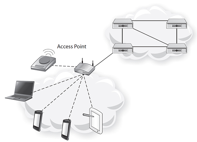
Figure 8-8 WLAN network
802.11 Standards
The 802.11 set of standards define how wireless LANs are to be implemented, their modulation techniques, and their protocols. These standards work in the 2.5 GHz band and in the 5 GHz band (which is also called the instrument, scientific, and medical [ISM] band and is an unlicensed band in most countries). Within each band are channels that make it possible to isolate the transmission of multiple APs in the same space. The 2.4 GHz band is shared with devices such as microwave ovens, cordless telephones, and Bluetooth, and therefore 802.11b and 802.11g devices that operate in the 2.4 GHz band suffer from interference. These standards use direct-sequence spread spectrum (DSSS) and orthogonal frequency-division multiplexing (OFDM) modulation techniques. The media access control mechanism is Carrier Sense Multiple Access with Collision Avoidance (CSMA/CA). Here, rather than sending out a message and sensing if a collision occurred, the transmitter waits for a signal from the AP that it is clear to send a signal before it sends the message.4
802.11a
This standard covers wireless WLANs in the 5 GHz range. There are eight channels in this frequency range, and each channel runs at 54 Mbps. NICs can be located a maximum of 300 feet from the AP. This is a legacy standard and is being supplanted by newer standards.
802.11b
This standard covers WLANs in the 2.4 GHz range. There are three channels in this range, with each channel running at 11 Mbps. The maximum range is 450 feet. This standard is also being supplanted by newer standards.
802.11g
This standard covers WLANs in the 2.4 GHz range. There are three channels in this range, with each channel running at 54 Mbps. The maximum range is 300 feet. It is backward compatible with the A and B versions. WLANs based on this standard are commonplace today.
802.11n
This standard covers WLANs in the 2.4 GHz range and the 5 GHz range. The speed the WLAN can achieve is up to 600 Mbps with a range of 450 feet. This standard achieves such high speeds partly because it uses a novel approach to antenna design that takes advantage of multipath propagation. The antennas used in this standard are called multiple-input multiple-output antennas (MIMO).
TIP Wireless site surveys are one approach to use when planning and designing a wireless network. Required wireless coverage ranges, data rates, network capacity, and other factors are taken into account during a site visit. Testing for RF interference, analysis of building floor plans, and other techniques lead to optimum placement of wireless access points.
Security
Unlike wired networks where network access is physical (you need to plug a cable into a port and that port is in a room that has a door that may be locked), wireless networks can be accessed by anyone who is within range of the wireless signal. Therefore, wireless networks need to be secured, especially if they happen to be carrying sensitive patient data. There are different ways of securing wireless networks, and some are more or less secure than others.
Not broadcasting the service set identifier (SSID) is a less secure way of securing a wireless network. To get on the network, the user needs to know the SSID. When the user enters it, upon getting prompted by the system, the user sends it to the AP. What makes it less secure is that the SSID is stored in plain text, which means anybody sniffing the WLAN can get the SSID. Another less secure way of securing the LAN is MAC filtering. When MAC filtering is used, only a specified set of MAC addresses are given access to the network. The reason it is less secure is that a hacker sniffing frames on a wireless network can read a MAC address and then use that MAC address to gain entry into the network.
Wired Equivalent Privacy (WEP) was the original security mechanism associated with 802.11. It required the user to manually enter a key, which would be used to encrypt transmitted data. Manual key entry limits scale and exposes WLANs to security breaches (keys being stored on sticky notes). Thus, WEP was replaced by Wi-Fi Protected Access (WPA) and then WPA2 (also known as 802.11i). 802.11i uses the Advanced Encryption Standard (AES) and is considered a more secure way of securing wireless LANs.4, 5
Other security measures that can be considered for healthcare networks include the following:3, 5
• Antenna and signal gain design that limits the WLAN footprint to the true usage perimeter.
• Policies preventing attachment of wireless devices to the enterprise network.
• Avoiding meaningful names for the WLAN SSID since this provides readily accessible information to hackers.
• Implementing intrusion detection methods on the WLAN. For example, the issuance of multiple incorrect SSID frames could trigger an event.
• Recognizing that the WLAN will always be a less secure network and then treating it as such by isolating it from the core network and placing appropriate safeguards, such as firewalls, between it and the core network.
Bluetooth
Also known as 802.15, Bluetooth covers data exchange over very short distances in the ISM band (2.4 GHz to 2.48 GHz). It supports fixed and mobile devices and is used in PANs. Bluetooth uses a modulation scheme called frequency-hopping spread spectrum (FHSS). Depending on which version of Bluetooth is being used, the data rate varies from 1 Mbps to 3 Mbps. The protocol used is a master-slave protocol where a master can control up to seven slaves. Examples of devices that use Bluetooth are laptops, wireless phones, iPhones, and GPS. Bluetooth can be used to transmit short-range health sensor data.1
WAP, WML, and HTML5
Wireless Application Protocol (WAP) is a standard that describes how browsers and servers communicate with each other over a wireless mobile network and defines an environment for application development. This standard includes a layered architecture similar to the OSI stack where the bottom layer, Wireless Datagram Protocol (WDP), is an adaptation layer to different wireless network technologies. The four layers above the WDP layer are then consistent for all communication devices and provide for interoperability. Figure 8-9 shows these layers. The Wireless Session Protocol (WSP) is analogous to a stripped-down version of HTTP. The Wireless Application Environment (WAE) originally included the Wireless Markup Language (WML), again analogous to HTML and based on Extensible Markup Language (XML).6

Figure 8-9 WAP protocol suite6
HTML5, the newest version of the Web’s markup language, has as some of its design objectives to support the development of cross-platform mobile applications, to run in low-power and small form factor devices such as iPhones and iPads, and to support multimedia applications found on these devices.
Cellular
Cellular networks provide users with the ultimate ability to be untethered anywhere, and it is possible that one day they will become the ultimate access method for telecommunications. Long Term Evolution (LTE) is the newest cellular network standard and has gained global acceptance. The designers of LTE had the following objectives in mind: take advantage of emergent digital signal processing techniques and modulation techniques, and use an IP transport fabric. The upload peak rate of LTE is approximately 75 Mbps, and the download peak rate is 300 Mbps. The multiplexing techniques used are frequency division duplexing and time division duplexing. Voice can be carried on the LTE networks using Voice over IP technologies, but there are also hybrid methods available to carry voice. LTE has a low data transfer latency of 5 milliseconds. LTE can support cell sizes that range from 10 meters up to 100 kilometers. There is backward compatibility with previous cellular systems.7
Sample Network
This section introduces a typical network, one that contains components found in most networks today. Each component and its function in the network will be described. A diagram of this network is shown in Figure 8-10.

Figure 8-10 Sample (typical) network diagram
Purpose of a Network
Since networks are expensive to equip, deploy, and maintain, they should have a value proposition. Fundamentally, networks connect things. The sample network shown in Figure 8-10 connects different departments of a hospital to a data center, the Internet, and a cloud service. A pharmacy and a gift shop are connected to applications in a data center. A surgical ward is connected to the network. In the clinic, a server, a terminal, and a phone are connected to applications in the data center. Lastly, a wireless access point in the emergency ward connects patients and members of families of patients to a wireless network. In today’s modern healthcare setting, this type of connectivity is expected by doctors, staff, the administration, patients, their families, and members of the public.
Components of the Sample Network
The following components are depicted in Figure 8-10: an Ethernet hub, network switches, routers, access points, a WLAN controller, and a firewall. Servers, tablets, smartphones, terminals, and VoIP phones are also shown in the diagram but will not be discussed since the focus of this chapter is on network components—not the end devices that attach to them. Servers do participate in the network via their network interface cards and also if they are running software that implements network components such as firewalls and routers.
Ethernet Hubs
The purpose of an Ethernet hub, also commonly known as a hub (and will be referred to as a hub going forward), is to distribute information (packets) from all devices and to all devices connected to it. A hub is said to work in broadcast mode, meaning it copies the information sent into one of its ports to all of the other ports. A hub also acts as a repeater and cleans up the physical digital signal sent to it. Ethernet hubs are equipped with RJ-45 ports and use the Ethernet standard. They are relatively simple devices and require little or no configuration other than connecting power and RJ-45 cables. At one time hubs were used extensively to connect network components; however, as the relative cost of network switches fell, hubs were eventually replaced by network switches, which could perform the same role but had more functionality.
Network Switches
The purpose of a network switch, also commonly known as a switch, is to forward traffic destined from a device connected to one of its ports to one or more ports of that switch. The term switch is generally used in telecommunications and networking and could exist in a number of different contexts; examples include telephone switches, ATM switches, and multilayer switches. This section focuses on layer 2 virtual LAN (VLAN) switches.
Layer 2 switches operate at the data link layer. These switches generally carry out the following functions: forwarding data traffic, filtering data traffic, and segmenting data traffic. A switch forwards data traffic by building up a forwarding table, also called a MAC address table. This table associates MAC addresses with switch ports. As a data link frame enters a port on the switch, its destination MAC address is read and compared to a list of addresses in a forwarding table, and if an entry exists, the frame is copied out to the port associated with this entry. If no entry exists in the table, then the frame is broadcast to all the ports of the switch except the port that the frame entered on. This broadcast should result in an acknowledgment from a responding device whose address is the same as the destination MAC address of the frame. As the acknowledgment frame comes back from the responding device, its source address will be read by the ingress port and stored in the MAC address table of the switch along with the ingress port ID. The next time a frame is sent using that MAC address, a forwarding entry will exist in the MAC address table and a broadcast will be unnecessary. The MAC address table is built up by having ports read the source MAC addresses as they enter a port on the switch. This process is most intense when the switch is initialized. Once the forwarding table is complete, the communications across the switch become more efficient.
A switch segments data traffic using VLANs. VLAN membership can be defined in different ways, including switch ports, MAC addresses, and IP addresses. Thus a specific set of switch ports can be associated with a specific VLAN. This capability can be aligned with corporate domains in an enterprise allocating VLANs to departments such as accounting, admissions, or pharmacy. The effect of VLAN functionality is that frames entering a particular port assigned to a particular VLAN will only be broadcast on other ports that are members of that VLAN. Data traffic will not move across VLANs (unless the VLANs are connected by a router). This segmentation makes the collision domain smaller, makes the communication more efficient, and helps security. Furthermore, much of the layer 2 switch functionality is provisioned in hardware rather than software, making a switch a high-performing network component.
A switch has different forwarding techniques to deal with the possibility of frames having errors or being malformed; two of these techniques are store and forward and cut-through switching. In the store-and-forward configuration, complete frames are read into the switch and verified for integrity before being forwarded. With this technique, frames with errors are not forwarded and do not waste the switch’s resources. With cut-through switching, the frame is forwarded once the destination address is received and read. With this method, latency across the switch is reduced, but it is possible to forward a frame in error.8
VLANs can be extended beyond a single switch. This is achieved using the 802.1Q protocol, which adds a label to the Ethernet frame. Thus, two switches can communicate over a common trunk by passing Ethernet frames with labels identifying the VLANs that exist on both switches. Layer 2 switches configured with 802.1Q on a port can be connected to a router that has an interface configured for 802.1Q, thus terminating multiple VLANs logically in the router. The router can then route traffic between these VLANs. This replaces multiple physical LAN connections into the router.
Layer 2 switches can be provisioned in different ways: desktop, chassis, and rack. They can have redundant systems such as CPU cards and power supplies. Depending on the speed of the interfaces, the associated ports can have either copper or fiber-optic interfaces. Switches can also be provisioned with Power over Ethernet (PoE), which provides power to end devices such as VoIP phones. Depending upon the sophistication of the Layer 2 switch, it can be either unmanaged or managed. Switch management is usually implemented through some type of command-line interface or by using the Simple Network Management Protocol (SNMP). Some configuration parameters that can be set include
• MAC filtering
• Spanning Tree Protocol (STP)
• Shortest Path Bridging (SPB)
• Simple Network Management Protocol
• Port mirroring
• Trunking8
Routers
The purpose of a router is to forward data packets to networks it is connected to and to interconnect and terminate LANs. Routers are also fundamental building blocks of the Internet. Routers come in all shapes and sizes: home routers that terminate ISP connections; large sophisticated enterprise routers; access, distribution, and core routers; and routers that act as firewalls. They are located in various parts of the network: at home, in small offices, in offices of global enterprises, and at the interface between large peer network providers. The routers shown in Figure 8-10 could be customer premises equipment (CPE) belonging to service providers or access routers that form part of an enterprise’s WAN. This section focuses on access routers.9
Routers work at layer 3, the network layer—they collectively move packets from a source to a destination in the network. To do this, routers execute two functions. The first is the creation of a routing table that contains information on routes that packets can take through the network. This routing table is made up of static routes, typically configured by network administrators, and dynamic routes, the result of distributed algorithms called routing protocols that routers execute. Dynamic routing algorithms are generally classified into two categories: distance vector and link state. Examples of routing algorithms include Routing Information Protocol (RIP), Open Shortest Path First (OSPF), Enhanced Interior Gateway Routing Protocol (EIGRP), and Border Gateway Protocol (BGP).9
The second function that routers execute is forwarding packets. They do this by comparing the network address part of the destination IP address of the transiting IP packet to the list of network addresses in the routing table. When a match is found, routers forward the packet to the next hop destination. If no match is found, they forward the packet to a default route. In many cases the default route is the Internet. A router’s performance is tied to how quickly it can perform these two functions.9
Routers connect LANs together. In the case of the sample network, Figure 8-10, the router is connecting multiple VLANs together. When routers connect to LANs, they terminate the LANs’ collision domains. The networks that routers connect to can have different physical media (e.g. copper and fiber). Routers have other functions as well, such as network address translation (NAT), port forwarding, and firewall functions.
Network Address Translation
Network address translation (NAT) is a method of mapping one IP address space into another by modifying network address information in IP packet headers while they move through a router.10 The NAT function provides two benefits to networks. It helps with security by hiding a network behind one address and helps alleviate the problem of IPv4 address exhaustion. Usually a public routable address on the outside of the network will be mapped to a private address space on the inside of the network.
NAT works by swapping the source address (usually a private address) of an internal host with a public external IP address in the transmitting packet. This is done for all packets that come from internal hosts: their respective private source addresses are swapped for the external publicly routed IP addresses. Then the unique combination of internal private address and port is associated with a specific port in the transmitting packet and tracked in a translation table. Different port numbers are chosen for packets sourced from different hosts. When the packets exit the network, they all have the same source address (the publicly routable address) but different port numbers that are tracked in a translation table. When the receiving host answers, it does so using the publicly routable source address as a destination address and uses the tracked port number. When the packet arrives at the NAT device, it uses the translation table to find the private address and port pair.11
There are problems with the NAT process for which workarounds are needed. For example, one can browse external web sites from the internal network but can’t browse internal web sites from the external network. Port forwarding can deal with this situation and is described next. Note that the foregoing discussion on NAT has been simplified; NAT is a complex topic.11
Port Forwarding
Port forwarding comes into play when NAT is used in a network. Because NAT effectively hides an internal network made up of many devices using many IP addresses (usually private IP addresses) and only exposes one public IP address, it’s impossible for an external request to be made on a service residing in an internal host in that network. Port forwarding maps the port (usually a well-known port such as port 80) with the internal IP address as the request traverses the network gateway (router). The request can then find the server in the internal network.12
Port forwarding is configured by having a network administrator reserve a port number on the router for the specific application/server that will need to be communicated with on the internal network. External clients/hosts wishing to access the application/server will need to be given this port number and the public gateway address of the router. Usually that port is then assigned to be used by the application/server only. Situations in which port forwarding is required include when remote users require access to e-mail servers, access to HTTP servers, or FTP access to an internal server from the Internet.13
Router Configuration
Routers can be configured from a console port, using a remote access program such as Telnet or via management systems. Most routers are configured using a command-line interface that is unique to the manufacturer. As stated previously, routers can be sophisticated devices, which means there are many things that could be configured on the router. The key configuration options are security parameters, hostname, login credentials, routing protocols and their parameters, interface configuration such as IP addresses and address ranges, network management, access control lists, and policies.
Wireless Access Points and WLAN Controllers
The purpose of this section is to discuss the use of WLAN controllers in the network, (wireless LANs and their standards have been covered in previous sections of this chapter). WLAN controllers make it possible to manage large numbers of WLAN access points—a situation that faces healthcare organizations, particularly if they have many branch locations and wish to extend WLAN services. Furthermore, users such as resident and visiting physicians, patients, and patient family members are becoming more reliant on mobile devices such as smartphones, tablets, and laptops. Healthcare organizations are also taking advantage of the benefits of networked but untethered devices such as mobile e-infusion pumps and glucose meters. The expectation is becoming greater to be able to communicate anywhere and anytime, creating the need for a reliable and smoothly functioning WLAN.14
When WLANs first started appearing, access points were installed in offices connected to the local Ethernet. This was manageable as long as there was a small number of these locations. Network administrators managed these access points individually and were able to make software upgrades, maintain the access points, and deal with security issues. However, as the number of access points increased, a need arose to provision central management. A solution to this is the centralized WAN controller where management, data, and control functions are concentrated on a single device.15
A characteristic of this centralized management architecture is that traffic travels from the access point to the controller and back again. In this architecture the controller has the intelligence and the access point has little or no intelligence. This provides advantages such as the ability to roam between access points, the deployment of security profiles to end devices, policy enforcement services, and scalability. As with any centralized architecture, this introduces a single point of failure as well as the possibility of congestion since traffic has to flow to and from a single point. Having said that, adding computer and power redundancy to centralized controller systems alleviates some of these concerns.15, 16
Another type of controller architecture is the distributed model using a hybrid approach—data stays at the edge instead of flowing back to a central point and some functions get centralized but the access points have more intelligence to manage local functions. Enterprises have a choice of approaches, either controller based or controller-less based. A controller-less approach means less cost (no central infrastructure required), no single point of failure, and possibly a simpler deployment environment depending on the size of the enterprise.16
Firewalls
The purpose of a firewall is to protect an enterprise’s internal network by limiting access to that network from the external network. Usually the firewall is protecting the internal network from the public Internet, but it could also be protecting internal networks from each other. As with other security components, firewalls align with the enterprise’s security policies. Firewalls fall under the topic of security and have broad scope, which is why they will be treated briefly in this section.17
Firewall functionality can be implemented in different ways: as standalone devices, as an application running on a server, virtual machines, and on other network devices such as routers (access control lists can be defined on routers to do basic packet filtering).17 Firewall functionality can also be combined in different ways. Two basic firewalls types are described next.
Network Layer or Packet Filter Firewalls
Network layer, also called packet filter firewalls, are basic firewalls that operate on TCP/IP packets. They either forward or filter packets based on rules associated with header information such as source and destination IP address, port numbers, or protocol types. Access control lists implement the rules. These firewalls further subdivide into stateless and stateful firewalls. Stateless firewalls work on a single packet at a time and do not retain information about that packet, whereas stateful firewalls “remember” characteristics about a session, which makes them better at detecting anomalies in packets that are part of that session.18
Application Layer Proxy Firewalls
Application layer firewalls operate at the application level of the Internet communications model. As proxies they are placed between the client and server in a client-server connection. They inspect the packets in depth and look for anomalies associated with application process flow and for improper content such as worms and Trojans.17, 18
Firewall Configuration
Firewalls are configured by defining rules. An example of a basic rule is the “implicit deny,” which by default prevents any packet from traversing a router unless an explicit rule is created to allow certain packets to get through. Another example is denying packets that have source addresses that exist on the internal network.17
The diagram in Figure 8-10 shows a firewall facing the Internet, protecting the internal network from threats coming from the Internet. In networks composed of many geographically dispersed networks and where mobile devices are being used, firewalls may be positioned at multiple locations to protect the edge of the network. In this circumstance, enterprises can take advantage of firewall management systems that provide consistent policies to multiple firewalls.
Cabling
The devices in Figure 8-10 will be interconnected using either copper or fiber media. The devices will likely be located in a data center or a wiring closet and will be interconnected using some type of structured cabling approach. Lower speed equipment will be connected using copper media, and higher speed equipment will be connected using fiber media. Patch panels will be used to organize cable runs, and patch cords will be used to make final connections.
The copper media used will typically be Category 5, 5e, 6, and 6a unshielded twisted pair (UTP) cable and patch cords terminated in RJ-45 connectors. The fiber media will likely be single-mode fiber cables and patch cords.
Use Case 8-3: Network Troubleshooting Scenario
Scenario
Bob had just finished installing all the equipment and cables for his data center upgrade in which he was moving from a physical network to a virtual local area network—see Figure 8-11. It meant that instead of connecting the clinic, pharmacy, and emergency LANs individually to separate ports on the router, he could connect them into a single switch, which then interconnected into one port on the router. VLANs gave him the flexibility he needed in the future to make changes.
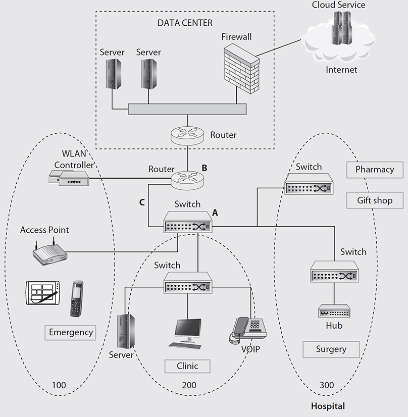
Figure 8-11 Sample (typical) network diagram for Use Case 8-3
Bob needed to verify that everything was working, so the first thing he did was to Telnet to Router B to check the MAC table. He expected to see the MAC table filled with MAC addresses associated with all the devices in VLANs 100, 200, and 300.
He was able to ping from Router B to Switch A. Switch A’s MAC table was filled with the entries he expected to also see in Router B. What was wrong and how could Bob fix it?
Resolution
Bob needed to check his router settings. He saw a complete MAC table on the switch, and with 802.1Q trunking on between Router B and Switch A, he should have seen all the MAC table entries in the router’s MAC table. He did not have 802.1Q turned on in the router for the interface that was connected to Switch A. Once he configured the router properly the switch could understand the frames and build the MAC table.
Transmission of Healthcare Data (HL7)
This final section of the chapter describes HL7, which is both a standards organization and a standard. The “L7” in HL7 refers to layer or level 7 of the OSI stack and relates to the healthcare applications that reside at the application layer.
According to www.hl7.org, “Founded in 1987, Health Level Seven International (HL7) is a not-for-profit, ANSI-accredited standards developing organization dedicated to providing a comprehensive framework and related standards for the exchange, integration, sharing, and retrieval of electronic health information that supports clinical practice and the management, delivery and evaluation of health services. HL7 is supported by more than 1,600 members from over 50 countries, including 500+ corporate members representing healthcare providers, government stakeholders, payers, pharmaceutical companies, vendors/suppliers, and consulting firms.”19
HL7 is a framework for exchanging data in healthcare and was a response to the costs associated with writing interfaces for the growing number of healthcare applications. Since the nature of healthcare applications is that they are unique, each interface is therefore different. That means for a given application, a developer needs to write an interface for every other application that the application will interface with. With HL7, a developer just needs to follow the standard for message exchange and knows that the application will interface with any other application that follows the HL7 standard.
There are two versions of the HL7 standard in existence today: HL7 v2 and HL7 v3. HL7 version 3 is an improvement over HL7 v2 since the people who defined it had the advantage of seeing what worked and didn’t work for HL7 v2. They also had the advantage of incorporating innovations in computing methodologies, best practices, and technological innovation such as XML in the intervening time between the HL7 v2 release and the start of HL7 v3’s development. Having said that, the majority of HL7 implementations today are according to HL7 v2, and there are two reasons for this. The first is that HL7 v2 was around for ten years, and it captured the initial investments in application development at that time. Second, one of the objectives of HL7 v2 was to have high adoption rates, and to do that, the designers purposely left about 20 percent of the standard flexible. Furthermore, HL7 v2 was focused on clinical interfaces and applications, whereas HL7 v3 is focused on medical informatics.20
Many of the functions and business processes in healthcare lend themselves to automation. This includes exchanging data between various suborganizations and systems within hospitals, between various political entities such as governments, and for use in health informatics. HL7 tries to standardize what are essentially unique healthcare models for hospitals, clinics, and labs. The value of HL7 comes from the network effect; the more people who use it, the greater its value becomes; and the greater its value becomes, the more people who use it. As the number of applications that use HL7 increases, the motivation to adopt it increases for those applications that have not yet adopted it.20
HL7 v2
Development on HL7 v2 began in 1987. Its design reflects the healthcare information concerns of the time, which were admissions, discharges, transfers, orders, and reports. HL7 v2 is also a flexible standard, meaning it can be added to over time, and this is why a key design principle of HL7 v2 is its backward compatibility.
The key HL7 v2 design concepts are message syntax, segment structure, fields, delimiters, data types, and vocabulary. In HL7 v2, messages are triggered by events. There are different message types, and each message is composed of segments. Each segment has a three-character identifier that comes first, followed by fields, which contain components and subcomponents. Delimiters separate these components and subcomponents. An example of a message type is the ORM message. ORM stands for an order message. Examples of delimiters include the field separator ( | ) and the component separator (^). Each segment has a definition table.21
The patient identifier (PID) segment is a very common segment across message types. It has a number of components, such as PID-5 (patient name) and PID-7 (date/time of birth). For example, a patient name would be represented as |john^doe|. Another example of a segment is the AL1 (allergy) segment, which contains patient allergy information, including codes for allergy type and severity. The BLG segment contains information about billing, such as the charge type, when to charge, and the reason for the charge. The IN1 (insurance) segment contains information about insurance policy coverage, for example, insurance plan and company ID. The MSH (message header) segment is included in every HL7 message and contains the source of the message, its purpose, and its destination. The OBR (observation request) segment contains information about exams, diagnostic studies, and observations and assessments specific to a result or order. As a final example, the SCH (schedule activity information) segment contains information about scheduled appointments. The Z segment is a special segment that enables developers to create their own segments, thereby allowing flexibility for “local” extensions to HL7 v2.
Segments contain fields. An example of a field within a segment is the Healthcare Provider Type Code field, which contains information to identify what type of provider cared for a patient. This field can be contained in an HL7 message within various segments, for example, the BLG segment. HL7 recommends using the Health Care Provider Taxonomy values—derived from another standard, ANSI ASC X12—in this field. For example, 207PS0010X is the code for Sports Medicine; an emergency physician with special knowledge in sports medicine.
Data types are another HL7 v2 design concept. Data types define the values, formats, and vocabulary that fields, components, and subcomponents can have. Data types are also categorized as simple and complex. Simple data types contain a single value, whereas complex data types may contain more than one, and each of those can be a different data type. An example of a simple data type is DT, or date. Its format is YYYY[MM[DD]]. An example of a complex data type is SAD, or street address, which includes the house number and street.21
HL7 v3
Development on HL7 v3 started in 1992 with an aim to improve upon HL7 v2. The development team had at its disposal the accumulated knowledge learned from the many existing implementations of HL7 v2 and was able to apply new IT best practices. It addressed the need for the following: a consistent application data model, formal methodologies to model data elements and messages, well-defined application and user roles, and precision in the standard.20
A key goal of the HL7 v3 development work was to create a more rigorous standard than HL7 v2, one that would lend itself to vendor conformance testing. HL7 v2 made vendor conformance testing difficult because there were a lot of HL7 v2 variants. These variants resulted from the flexible design of HL7 v2, which made it possible to have optional data elements and segments. This left it up to implementers to ensure conformance.
HL7 v3 combines object orientation and a Reference Information Model (RIM) to create HL7 v3 messages. This results in a standard that is extensible, is current, can be conformance tested, is abstracted from technology, and covers healthcare exhaustively. At the top of the RIM backbone, there are three main classes:21
• Act, which refers to something that has happened or will happen
• Role, which is a position, job, or competency
• Entity, which is something that is living or nonliving
The meaning of each class is determined by structural attributes. These three are linked using the association classes ActRelationship, Participation, and Rolelink. As in HL7 v2, there are data types defined such as name and addresses. Figure 8-12 shows an example of patient identifier coding in HL7 v2 and HL7 v3. The purpose of this example is to convey the structural difference in how the information is coded; it is not necessarily an accurate depiction. Note that HL7 v3 has adopted the XML style.
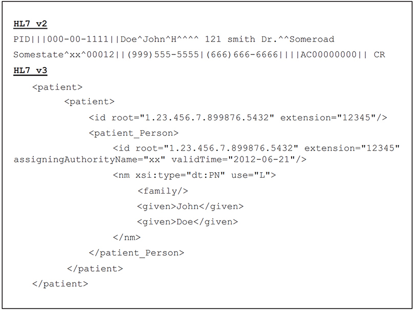
Figure 8-12 Comparison of HL7 v2 and v3 coding
Advances in networking hardware and software discussed in this chapter, HL7, and other health data standards such as ANSI ASC X12 in the past three decades have enabled vast increases of volume of healthcare network transmissions. Despite this progress, ever increasing volume creates the potential for problems. For HL7 messages, problems may include incomplete data transmission, data being transmitted in wrong segments, deactivated threads or nodes, missing or incomplete patient data in key segments, data out of order and potentially misread, and scrambled or timed-out messages (for example, due to fax or network failure), all potentially leading to medical error. In healthcare, network administrators must be keenly aware of the potential for such issues.
HL7 FHIR
Fast Healthcare Interoperability Resources (FHIR), pronounced “fire,” is a relatively new, emerging specification for exchanging healthcare information electronically. In early implementations, FHIR is building on and working with HL7 v3 implementations. FHIR uses many approaches and standards that are used in network computing broadly across industries, such as XML and JSON formats, and is implemented using REST and/or service-based architecture.22 This exciting development represents an opportunity for the healthcare industry to leverage existing and already widely adopted interoperability standards and, importantly, the many experienced people who have used these standards in other industries.
EHR Outbound Communication
Electronic health record (EHR) systems frequently need to interoperate with one of many other systems within a healthcare organization, and also with systems outside of the organization. In the vast majority of cases in the United States, this is accomplished by system-to-system software interfaces that comply with HL7 standards.
Let’s see how this works with a billing example. Some EHR systems have a billing module that interacts directly with other modules, such as the ADT (admission, discharge, transfer) module. If a healthcare entity uses that billing module within its EHR system, no interface from the EHR system to the billing module is required. Quite a few billing systems, independent of a healthcare entity’s EHR system, predate the current EHR system, and the billing departments have often prevailed over the IT department to maintain the independent billing system. Some of these billing systems are subsystems or modules of practice management systems. In some cases, a particular EHR system does not have a billing module. When an independent billing system is preferred or required, an interface between the EHR system and billing system is required. HL7 handles EHR-to-billing-system outbound communication with the BLG segment. In many cases the technical management of these interfaces is managed by a third system known as an interface engine.
Chapter Review
Internet and wireless technologies are changing how telecommunications services work and are provided in healthcare. The Internet holds the promise of converging voice, video, and data traffic onto a single network. Wireless technologies promise to extend connectivity to people anywhere and at any time. These changes are also motivating healthcare innovations as telecommunications is applied to problems in clinical settings, making it possible for clinical staff to work with greater flexibility and sometimes do things they couldn’t do previously.
This chapter focused on TCP/IP networks since they will likely be the transport networks of the future. Concepts necessary to the understanding of how TCP/IP networks work were introduced: connectivity, communications models, communications protocols, throughput, addressing, applications, and PANs, LANs, MANs, and WANs. To understand how networks work, it is useful to know how data flows. The chapter covered two examples of data transfer: transfer between two workstations on the same LAN and data transfer between a workstation and server on a different LAN. Wireless networks offer the benefits of mobility to clinicians, which makes the provision of services to patients more efficient and effective. The predominant wireless LAN technologies and standards were covered.
The “Sample Network” section built on the foundations of the previous sections and described key components of networks such as hubs, switches, and routers. Methods of managing networks, such as network address translation, port forwarding, and router configuration, were discussed. Key tools such as wireless access points and WLAN controllers, firewalls, and cabling techniques for networks were covered. Finally, the HL7 standards (and the standard development organization by the same name) were introduced. This important set of standards, including its existing v2 and v3 main forms and its emerging FHIR standard, governs much of what is transmitted on healthcare computer networks.
Questions
To test your comprehension of the chapter, answer the following questions and then check your answers against the list of correct answers at the end of the chapter.
1. How many connections would be needed to fully connect six people?
A. 6
B. 15
C. 12
D. 18
2. A PDU has what basic structure?
A. A beginning delimiter and ending delimiter with a payload between these two delimiters
B. A beginning delimiter and ending delimiter, source address and destination address fields, a control field, a payload field, and an error check field
C. Source address and destination address fields and a payload
D. A control field and a payload
3. Which layer of the OSI model is responsible for determining the best route through a network?
A. Network layer
B. Physical layer
C. Session layer
D. None of the above
4. With a client-server architecture, _________________.
A. one or more clients request the services of one server
B. each device is a client and a server
C. one or more servers request the services of clients
D. it is better to work at a small scale since there is little overhead
5. While a network layer PDU traverses the network, _________________.
A. its destination MAC address never changes
B. the source IP address is matched to the last gateway it passes
C. its destination IP address is changed to that of the first router it encounters
D. its source and destination addresses do not change
6. What is different about wireless networks versus wired networks?
A. A wireless network is constrained to a 1-meter radius versus a wired network that can span rooms or city blocks.
B. The OSI stack is different for a wireless network versus a wired network.
C. Wired networks use radio waves to communicate.
D. Wireless networks use radio waves to communicate.
7. An Ethernet hub _________________.
A. is a repeater that cleans up the digital signal
B. is another term for a network switch
C. replaced switches as a network element
D. cannot be used to distribute a digital communication
8. HL7 v2 _________________.
A. is no longer used
B. has the majority of implementations because vendors discounted prices greatly
C. is exhaustive and rigorous because it has an RIM
D. has the majority of implementations because adoption was a design goal and the developers purposely made it flexible in order to get that adoption
Answers
1. B. n × (n – 1)/2 = 6 × (6 – 1)/2 = 15 connections would be needed to fully connect six people.
2. B. There are seven basic fields: a beginning delimiter and ending delimiter, source address and destination address fields, a control field, a payload field, and an error check field.
3. A. The network layer is responsible for routing and therefore figuring out the best path through the network.
4. A. Client-server architecture by definition is many-to-one since the resources are centralized in the server.
5. D. While a network layer PDU traverses the network, its source and destination addresses do not change, which is how the end-to-end capability of TCP/IP is guaranteed.
6. D. Wired networks use wires, and wireless networks depend on radio waves.
7. A. An Ethernet hub is a repeater that cleans up the digital signal. It serves some of the same purposes as network switches but should not be confused with network switches, which perform the same role but have more functionality.
8. D. HL7 v2 has the majority of implementations because adoption was a design goal and the developers purposely made it flexible in order to get that adoption. Another factor is that it was the first and only standard for ten years until HL7 v3 was written.
References
1. FitzGerald, J., & Dennis, A. (2009). Business data communications and networking, tenth edition. John Wiley & Sons.
2. Schulzrinne, H. (1996). World Wide Web: Whence, wither, what next? IEEE Network Magazine, 10(2), 10–17.
3. Cisco. (2010). Cisco Medical-Grade Network (MGN) 2.0: Wireless architectures. Accessed on January 29, 2017, from www.cisco.com/c/en/us/solutions/enterprise/design-zone-industry-solutions/index.html..
4. Hiertz, G., Denteener, D., Stibor, L., Zang, Y., Costa, X. P., & Walke, B. (2010). The IEEE 802.11 universe. IEEE Communications Magazine, 48(1), 62–70.
5. Bragg, R., et al. (2004). Network security: The complete reference. McGraw-Hill/Osborne.
6. Danielyan, E. (2003). WAP: Broken promises or wrong expectations? Internet Protocol Journal, 6(2). Accessed on June 16, 2016, from www.cisco.com/c/en/us/about/press/internet-protocol-journal/back-issues/table-contents-24/wap.html.
7. Parkvall, S., Furuskar, A., & Dahlman, E. (2011). Evolution of LTE toward IMT-Advanced. IEEE Communications Magazine, 49(2), 84–91.
8. “Network switch.” Wikipedia, April 11, 2016. Accessed on June 16, 2016, from https://en.wikipedia.org/wiki/Network_switch.
9. “Router (computing).” Wikipedia, May 30, 2016. Accessed on June 16, 2016, from https://en.wikipedia.org/wiki/Router_(computing).
10. Javvin Technologies. (2005). Network protocols handbook, second edition (p. 27). Javvin Technologies.
11. “Network address translation.” Wikipedia, June 9, 2016. Accessed on June 16, 2016, from https://en.wikipedia.org/wiki/Network_address_translation.
12. “Definition of: port forwarding.{{#}}8221; PC Magazine, October 11, 2008. Accessed on June 16, 2016, from www.pcmag.com/encyclopedia/term/49509/port-forwarding.
13. “Port forwarding.” Wikipedia, March 25, 2016. Accessed on June 16, 2016, from www.wikivisually.com/wiki/Port_forwarding.
14. Savage, M. (2016). Upgrading the network in healthcare: Two approaches. Network Computing. Accessed on June 16, 2016, from www.networkcomputing.com/cloud-infrastructure/upgrading-network-healthcare-two-approaches/732001772.
15. Cisco. (2016). Cisco wireless controllers at a glance. Brochure. Accessed on June 16, 2016, from www.cisco.com/c/dam/en/us/products/collateral/interfaces-modules/services-modules/at_a_glance_c45-652653.pdf.
16. Chubirka, M. (2013). Evolution of the WLAN controller. Network Computing. Accessed on June 16, 2016, from www.networkcomputing.com/networking/evolution-wlan-controller/1123406767.
17. Harris, S. (2013). CISSP all-in-one exam guide, sixth edition (pp. 628–651). McGraw-Hill Education.
18. “Firewall (computing).” Wikipedia, June 12, 2016. Accessed on June 16, 2016, from https://en.wikipedia.org/wiki/Firewall_(computing).
19. Health Level Seven International. (n.d.). About HL7. Accessed on January 29, 2017, from www.hl7.org/about/index.cfm?ref=nav.
20. Corepoint Health. (n.d.). The HL7 evolution: Comparing HL7 versions 2 and 3. Accessed on January 29, 2017, from www.slideshare.net/Corepoint/comparing-hl7-v3-with-hl7-v2.
21. Benson, T. (2010). Principles of health interoperability HL7 and SNOMED. Health Informatics series. Springer.
22. HL7. (2015). FHIR overview. Accessed on July 1, 2016, from https://www.hl7.org/fhir/overview.html.