
CHAPTER 9
Systems Analysis and Design in Healthcare
Andre Kushniruk, Elizabeth Borycki
In this chapter, you will learn how to
• Describe the importance of good systems analysis and design for healthcare information technology
• Implement systems design and analysis principles and methods
• Utilize the systems development life cycle (SDLC)
• Apply traditional approaches to systems analysis and design
• Employ object-oriented approaches to systems analysis and design
• Describe trends in systems analysis and design in healthcare
Increased information demands are leading to the development of more advanced healthcare information systems (HISs) and healthcare information technology. This chapter introduces the main concepts and techniques of modern systems design and analysis as applied to HISs. At the core of successful system development in healthcare is good systems analysis and design. This involves the selection and use of appropriate methods of analysis for assessing the information needs of a healthcare organization. System design involves specifying in detail how the components of systems will work together to provide useful functionality. As you will see, this needs to be based on an in-depth understanding of healthcare problems and the needs of healthcare professionals.
This chapter aims to describe the role and importance of systems analysis and design in rapidly changing healthcare environments. Approaches to systems analysis and design will be described, including traditional structured approaches to systems development and modeling of system requirements and design. Additionally, newer approaches such as object-oriented (OO) systems analysis and design as well as Agile system development will be described. Different design and implementation strategies and methodologies will be described, with an emphasis on understanding their advantages and disadvantages as they relate to healthcare. The reasons for the success and failures of HISs will be discussed, along with consideration of designs that might have helped to avoid failures. Approaches to system design will also be discussed in the context of a variety of healthcare information systems, ranging from electronic health record (EHR) systems to decision support systems. It has become increasingly clear that engineering information systems in healthcare is complex and requires the careful and informed application of appropriate methods and approaches to developing information systems. In this chapter, we will discuss the need for improving the development of information systems, and we will provide you with the background for understanding the complexity of HIT. We will also introduce a range of methods that can be used for improved systems analysis and design.
Systems Analysis and Design in HIT
A system can be defined as a collection of interrelated components (subsystems) that work together as a whole to achieve an outcome.1 There are many types of systems, ranging from biological systems to political systems. A health information system is a collection of interrelated components or subsystems that input and process data to produce an output that is needed for healthcare tasks. For example, EHR systems have been designed to support physicians’ use of information in dealing with patients.2 An EHR system might consist of the following subsystems: patient scheduling, medications, documentation, laboratory information, and diagnostic imaging. As shown in Figure 9-1, these subsystems could be broken down further into subsystems (e.g., the medication subsystem could be broken down into a computerized physician order entry [CPOE] subsystem and a medication administration record [MAR] subsystem). In addition, computer systems contain both manual and automated processes, which is an essential consideration, where some parts of the system involve manual activities (such as the entry of patient data by a clinician into a system using a keyboard) and some parts are automated or internal to the system (such as the automated application of decision rules for the detection of adverse drug interactions).
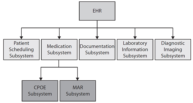
Figure 9-1 Subsystems of an electronic health record system
The Systems Development Life Cycle (SDLC)
A systems development project is a planned undertaking that produces an HIS. The development of any new information system involves analysis, design activities, and implementation activities. Systems analysis refers to the process of understanding and specifying in detail what the HIS should do. The results of a systems analysis form the foundation or basis for a specific system design. System design refers to the process of specifying in detail how the components of the HIS should work together to achieve desired functionality. A systems analyst is an IT professional who uses analysis and design techniques to solve healthcare problems using HIT. Systems implementation uses the results of the analysis and design processes to build, test, and deploy the system in a healthcare setting.
A central concept in HIS development around which activities, methods, and approaches are considered is the systems development life cycle (SDLC). The SDLC is a term used to describe the process and stages in the development of new HISs. The SDLC provides guidance to HIS developers by providing structure, methods, and a checklist of activities needed to successfully develop an HIS. As shown in Figure 9-2, the typical phases in the SDLC are the following:1
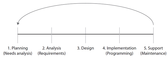
Figure 9-2 The systems development life cycle
1. Planning phase
2. Analysis phase
3. Design phase
4. Implementation phase
5. Support phase
The Planning Phase
The first phase—the Planning phase—involves coming up with the initial idea for an HIS development project. This includes identifying a healthcare problem that needs to be addressed and defining what aspects of the problem can be improved using healthcare information technology. During this phase, a feasibility study may be undertaken where the objectives and scope of the project are presented, the current problems with the existing situation are considered, and a recommended HIS solution is proposed. This phase may involve input from a manager and systems analysts working together to come up with a proposal for an organization to develop an HIS. At this point, if the project appears to be worth pursing (i.e., the projected benefits outweigh the costs), the project will then move into the Analysis phase.
The Analysis Phase
In the Analysis phase, a detailed assessment of the current situation is undertaken to determine where and how an HIS can be applied to solve healthcare problems. This may involve systems analysts going into a particular hospital setting (such as an emergency department or clinic) and collecting information about information gaps and problems that might be improved through the use of HIT. During this phase, the systems analysts involved in the project begin to gather information about the requirements for the new HIS that will be developed. This includes determining technical requirements for the HIS. Some examples of technical requirements include the following:1
• The HIS must run in a Windows 10 environment.
• The response time of the system to user queries must be less than one second.
• The data in the system must be backed up at the end of each day.
The functional requirements of the HIS describe the specific functions the HIS should support, with some examples of functional requirements for an HIS including the following:1
• The system will allow physicians to enter medication orders.
• The system will allow nurses to view medication orders.
• The system will provide automated alerts when entering a medication that the patient is allergic to.
Nonfunctional requirements make up the third major category of requirements for HIS; they include requirements for the system that are neither technical nor functional but are essential, such as the requirement that the system have a high level of usability and that the system functions can be learned easily by users with minimal prior computer experience.3

TIP Systems analysis refers to describing what a system should be able to do and involves specifying system requirements (i.e., technical, functional, and nonfunctional requirements).
Requirements gathering is a major activity that occurs during the Analysis phase. This may involve a team of analysts whose aim is to understand the current work situation and determine the requirements for the new HIS. This includes describing each of the following (see Figure 9-3):
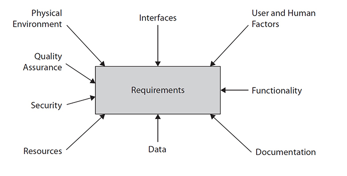
Figure 9-3 Summary of types of requirements in an HIS
• The physical environments in which the newly developed system will be deployed
• The different types of interfaces to other computer systems (e.g., laboratory data or other data may need to be obtained directly from other systems)
• User and human factors considerations that will need to be addressed
• The actual functionality of the system
• The level of quality assurance (i.e., how error free must the system be)
• The security considerations
• The human, computing, and other resources needed to operate the system
• The data inputs and outputs
• The technical and user documentation to use, update, and safely run the system
Systems analysts use a range of methods to obtain the requirements of an HIS, including the following:
• Distributing questionnaires to stakeholders and end users (e.g., to physicians, nurses, and allied professionals who will be users of the system being developed) to assess issues with current systems and requirements for new ones
• Reviewing organizational documentation, existing reports, forms, and procedure descriptions
• Conducting interviews with end users (e.g., physicians, nurses, allied health professionals)
• Observing current work practices (e.g., watching health professionals in an emergency setting to determine requirements for a new emergency room information system)
From the software engineering literature, as well as from the growing literature describing HIS implementations worldwide, there are two key points that need to be considered. One key consideration is that weak analysis of system requirements (i.e., performing an incomplete requirements analysis before proceeding with system design) will lead to “shortchanged user requirements,” which have been highly associated with failed projects, because incomplete requirements form an insufficient base for design of effective systems.4 The complexity of the environments where an HIS is deployed, the many and varied uses, and the variety of users of systems (ranging from clinics to hospitals to users of systems including physicians, nurses, and allied health professionals) all make gathering “sufficient” information about requirements difficult and challenging. The literature is full of examples of system development that has led to HISs that have not met user needs, that have not worked, or that had to be “turned off.” The other key consideration for an HIS is that research in software engineering has indicated that perhaps the single greatest factor in the failure of complex systems is a lack of end-user input and involvement.4 To avoid system failure and to ensure effective system design, consultation with end users should begin in the systems Analysis phase and continue throughout the whole SDLC through completion of the system’s development and testing. This will be described in the following sections.
Use Case 9-1: Conducting Interviews to Determine Problems with a Hospital System
In this case study, we will examine the interview protocol that was created for gathering requirements about a new HIS that was to be implemented in order to replace an existing system, which had been reported to have a number of problems. In this example, a set of questions was created that were to be asked of physicians in the clinic where the new system would be implemented. The questions focused on understanding what the problems with the existing system were. The following is the set of questions that was developed for this purpose:
• How often do you use the current system?
• For what purposes?
• Have you had any problems using the system?
• Can you give me some examples of problems you have encountered?
• Are there new features you would like to see in an improved system?
These questions were used to drive interviews with 20 physicians who were the end users of the current system. The interviews were recorded and transcribed for analysis in order to identify all problems with the current system that needed fixing. The following is the transcript from one of the first physicians interviewed (with responses in bold):
Systems analyst: How often do you use the current system?
Doctor: About two or three times a day.
Systems analyst: For what purposes?
Doctor: To check the values of the patient for abnormal levels.
Systems analyst: Have you had any problems using the system?
Doctor: Well, I am finding that the data presented is not correctly updated and also that I have problems accessing the system from home.
Systems analyst: Can you give me an example of the data not being current?
Doctor: Yes, some of the records do not contain reports that were generated at other hospitals, and the data from this hospital sometimes is mixed up with data from other patients.
Systems analyst: Really, can you show me an example?
Doctor: Yes I’ll show you this one I just printed out.
Systems analyst: Anything else?
Doctor: Yes, X-ray reports do not show on the system for at least several days.
Systems analyst: Are there new features you would like to see in an improved system?
Doctor: I would like to see guidelines about how to interpret abnormal lab values presented to me on the screen when an abnormal value appears.
Based on an analysis of all 20 interviews, it was clear a number of problems or themes kept reappearing from the interviews, such as the problem of information not being updated correctly and data being incorrectly displayed, as well as long delays in getting patient data. Based on these findings (and results from other forms of requirements gathering, including giving out questionnaires to both physicians and nurses), the requirements were specified for a new system that would replace the old one and that would address these issues. Specifically, the new system would be required to provide more timely updates of patient information, always present correct patient data, have a reduced period of time for providing physicians with reports, and have online guidelines for users to help them in interpreting abnormal lab values.
In general, the activities involved in conducting requirements analysis include the creation of a report, or a requirements specification, with a number of major sections, including the following:5
• Analysis method A list of end users consulted and a description of the methods used to obtain requirements (e.g., observation, interviews, or questionnaires).
• Statement of user requirements The objectives of the system, as well as all the technical, functional, and nonfunctional requirements that are listed. The potential impact of the system on end users and the need for training are discussed.
• Statement of system constraints The constraints of the system when it will be implemented in the real setting of use.
• Documentation Summaries of interviews and questionnaire results, as well as a set of diagrams describing the system requirements.
The requirements specification includes a number of key diagrams in the Documentation section. These diagrams form the basis or foundation upon which the sound design of the system will be based. The diagrams included in the report will depend on what type of approach is being used to collect and specify system requirements, as will be described.
There are many approaches and tools that are used to aid in collecting and specifying system requirements. One such approach is known as the traditional, or structured, approach to systems analysis and design. This approach includes a number of different diagramming techniques and tools. One such diagram that has traditionally been used in structured systems analysis is known as the data flow diagram (DFD); see Figure 9-4 for a simple HIS example of a DFD, along with a key indicating the meaning of the symbols used in the diagram. In the diagram, computer processes are depicted as rounded rectangles, while data stores or entities that are used by the processes are depicted using open-ended rectangles. The arrows show the flow of data from external agents into and out of processes, and the types of data are labeled on the arrows. In this example, Drug Order data flow into the Process Drug Request process from the Doctor, and data labeled Confirmation flow back to the Doctor after the drug request is processed. This type of diagram can be used to show how information flows and is processed in a healthcare organization to describe the current, or “as is,” situation. It can also be used to describe how information will flow in the proposed HIS that will replace the current situation.1
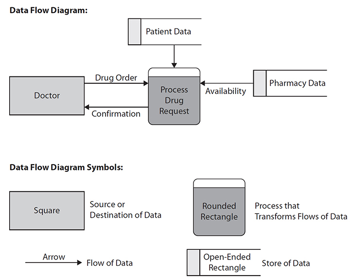
Figure 9-4 Data flow diagram symbols and simple example
Other types of diagrams and tools associated with traditional structured analysis include entity relationship diagrams (ERDs) that describe the relationship among the “things” of interest for designing a system, such as patient data, pharmacy data, and so on, which are depicted as boxes in the ERD and labeled as shown in Figure 9-5. In this figure, there are three entities: Patient, Doctor, and Patient Record. Within each box representing an entity are its attributes. For example, within the entity Patient, the attributes are Name, Address, and Patient Number. Each Patient is associated with (can have) only one Patient Record (in this hospital system), and likewise each Patient Record can be associated with only one Patient. The two small vertical lines on the horizontal line between Patient and Patient Record indicate this relationship. Likewise, there is the line connecting Patient and Doctor, showing there is a relationship between these two entities, with crow’s-feet markings (the small circles with three small lines coming from them) to indicate that Patients can have zero or more (could be many) Doctors and alternatively that Doctors can have or be associated with zero or more Patients. These diagrams are very important in that they form a blueprint for creating and designing the databases that underlie HISs, with entities in such diagrams being implemented as relational database tables.1
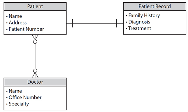
Figure 9-5 Example of an entity relationship diagram
TIP Entity relationship diagrams and data flow diagrams are examples of diagrams associated with structured systems analysis.
In contrast to traditional structured systems analysis and design, more recent approaches have appeared, including object-oriented (OO) systems analysis and design, which defines a newer set of associated diagramming techniques and tools to support work in the Analysis phase.6 OO systems analysis and design involves using a set of diagrams that are defined in the Unified Modeling Language (UML). UML diagrams have become a standard way of representing user requirements for many HISs and are commonly used to represent key aspects of current and proposed HISs in terms of system requirements. One such UML diagram that is commonly used to describe HIS requirements is known as the use case diagram.6
Figure 9-6 illustrates a use case diagram for a computerized physician order entry system. In the diagram, a figure represents an actor (i.e., a type of user of the system to be developed), in this case a physician. The main outer circle represents the automation boundary, which separates the computer system to be developed from manual parts of the system and end users outside of the automation boundary. In Figure 9-6, the three smaller circles inside the larger circle represent three use cases, which are the individual activities that the system can carry out. The arrows from the physician to the three use cases indicate that the actor is involved in each of the use cases (i.e., the physician user initiates each of the use cases). In the diagram there are three use cases shown: Order New Medication, Review Medication, and Stop Medication. Note that this type of diagram indicates who the users of the system will be (i.e., the actors) and also indicates what they can use the system to do. Since this diagram is constructed in the Analysis phase, it describes what the system will do, not how it will be done. (The description of how the system will carry out the functions illustrated in the use case diagram will be described during the Design phase, which follows the Analysis phase.) This type of diagram is increasingly used in order to give a clear view of system requirements. Each use in the diagram can be expanded to include a detailed text description of how the actors and the use case interact (i.e., scenarios describing in detail the interactions between the user and the system in carrying out a use case like Order New Medication).
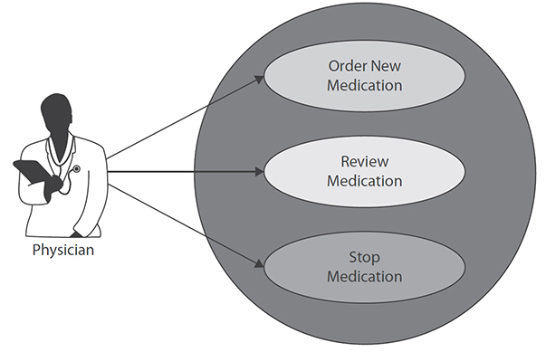
Figure 9-6 Use case diagram for CPOE system
Use Case 9-2: Representing Requirements for an HIS in UML
Based on requirements gathered during the Analysis phase, a patient record and scheduling system are being designed for use in a doctor’s office by receptionists, nurses, and doctors. The receptionists will use the system to enter new patient information when first-time patients visit the doctor and to schedule all appointments. The nurses will use the system to keep track of the results of each visit and to enter information about patient care. The nurses will also be able to print patient reports or the history of a patient’s visits. The doctors will primarily use the system to view the patient’s history and enter patient diagnostic and treatment information, as well as print patient information. Figure 9-7 shows the use case diagram for describing the requirements for the system based on this description. The three actors (i.e., receptionist, nurse, and doctor) are represented as figures, while the use cases (i.e., the activities the system will need to carry out based on the earlier description) are represented as the smaller circles within the larger circle representing the entire system.
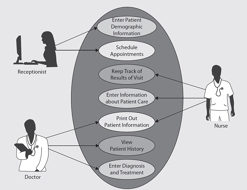
Figure 9-7 Use case diagram for patient record system
Another diagram initially developed during the Analysis phase when using the OO approach to systems analysis and design is called the class diagram.6 The class diagram is used to represent the “objects” in the work environment that need to be modeled and included in the HIS being developed. Objects have some surface-level similarities to the entities in the ERD described earlier, from a traditional structured systems analysis and design standpoint. However, the class diagram is different from the ERD in a number of important ways. For example, in developing a clinical decision support (CDS) module of an HIS, as depicted in Figure 9-8, several types, or classes, of objects need to be understood and modeled. In the figure there are three classes of objects depicted in rectangles: Clinical Decision Support, Drug Alert, and Drug Reminder. Each class of objects has its own attributes. For example, the attributes of Clinical Decision Support are Invocation Style, Message Text, and Message Format, thus indicating that all types of clinical decision support have a particular way of being invoked, have some text to be displayed to users, and have some particular format for messages to users. The classes Drug Alert and Drug Reminder are subclasses of Clinical Decision Support, which is shown by the arrow with a triangle leading up to Clinical Decision Support. This means they inherit all of the attributes of Clinical Decision Support. Thus, Drug Alert and Drug Reminder are types of Clinical Decision Support and have all the features of their superclass Clinical Decision Support. In addition, Drug Alert and Drug Reminder have their own attributes specific to them. For example, every Drug Alert has an Urgency Level and an associated Drug Alert Rule.
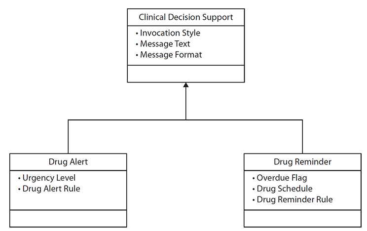
Figure 9-8 Class diagram for clinical decision support components
The Design Phase
The results of the Analysis phase provide a foundation for the Design phase of an HIS. Obtaining the “right” information from the Analysis phase is critical to the success of HIS design. Based on the requirements gathered during the analysis, the design of the system is specified during the Design phase. The design can be considered the blueprint that specifies how the system will work. This is in contrast to the Analysis phase, which focuses on what the system will be able to do; in the Design phase, you move on to the consideration of how the system will do it. System design also involves the intensive use of diagramming and modeling techniques, as will be described. A wide range of design approaches and methodologies can be used to drive the design of complex systems such as an HIS. These range from traditional structured approaches to object-oriented approaches.1 There are a number of considerations to keep in mind when moving from the Analysis phase to the Design phase, including the following:
• Has there been sufficient requirements gathering on which the design can be based?
• Will there continue to be sufficient end-user feedback during the design of the system?
• Is the appropriate design methodology being used for designing the system?
The design of an HIS includes the specification of the following:
• Designing the application architecture (i.e., describing how each system activity and function specified from the Analysis phase is carried out)
• Designing and integrating the network needed (i.e., specifying how the various parts of the system will communicate)
• Designing the user interface (i.e., specifying how users will interact with the system)
• Designing system interfaces (i.e., specifying how the system will work with other systems)
• Designing the underlying database (i.e., specifying how the system will store data)
As will be discussed, it is often recommended that an HIS design be carried out using an iterative approach that includes developing prototypes (partially working, limited versions of the system design) that can be quickly shown to end users to gain input and feedback into design (well before the design is finalized).7 The result of the Design phase is essentially the “blueprint” for the HIS; this includes a range of models and diagrams that specify the needed components of the system and provide detail on how they will work and interact.
One of the most commonly used diagrams used for traditional structured HIS design is known as a structure chart, as depicted in Figure 9-9. The structure chart shows the modules of a system and their relationships. A module, which is represented by a box in the figure, is an identifiable component of a system that performs a desired function. This diagram shows a top-down hierarchical depiction of modules of a system. For example, the top module called Create New Medication Order has three immediate submodules below it: Record Medication Information, Process Medication Order, and Produce Confirmation. In turn, the module Record Medication Information can be broken down into the four modules below it: Enter Med Name, Enter Med Dose, Enter Med Route, and Enter Med Frequency. The lines in the chart show the calling structure from high-level modules down to ones at the bottom of the chart. For example, in Figure 9-9 you can see that from left to right, the top, or boss, module Create New Medication Order will first invoke or call Record Medication Information (e.g., to obtain input from the user about the medication to be recorded); then the boss module will call Process Medication Order (to actually process the medication order, check for drug interactions, send the information about it to a medication database, etc.), which is finally followed by the boss module calling the module Produce Confirmation (which displays to the end user a confirmation that the order has been made). It should be noted that some of these modules will themselves likely need to be broken down further. For example, Process Medication Order could be broken down to multiple submodules during the design process. This is known as stepwise refinement.
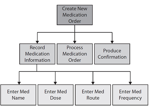
Figure 9-9 Structure chart for the activity Create New Medication Order
Using the object-oriented approach to systems design, an important type of diagram is called the sequence diagram.6 With each use case developed during the Analysis phase, a corresponding sequence diagram is created to show how the use case actually works. For example, Figure 9-10 shows a corresponding sequence diagram for the use case Order New Medication (listed as one of the use cases from Figure 9-6). An important part of sequence diagrams is the concept of sending “messages” to objects that are needed to carry out functions required in a certain sequence over a period of time. The sequence diagram shows how the user initiates the interaction with the CPOE by first sending the message Create Order to the User Interface object, as shown in the top-left horizontal arrow from the actor to the User Interface object. The Create Order message includes in it the parameters for the following: the name of the medication to be ordered (i.e., Med), the dose, and the frequency (Freq). Next, the User Interface object sends the message Check Order to the CPOE object. That object in turn sends a Record Order message to the Patient Record object. Next, notice the arrows going in the other direction from the Patient Record object back to the CPOE object, back to the User Interface object, and finally back to the user, providing the user with a confirmation of the order. This simple example shows that the sequence diagram can elaborate on and provide design details for how a single use case works by showing how different system components interact with each other by sending messages to each other in sequence over time to carry out an activity such as CPOE.
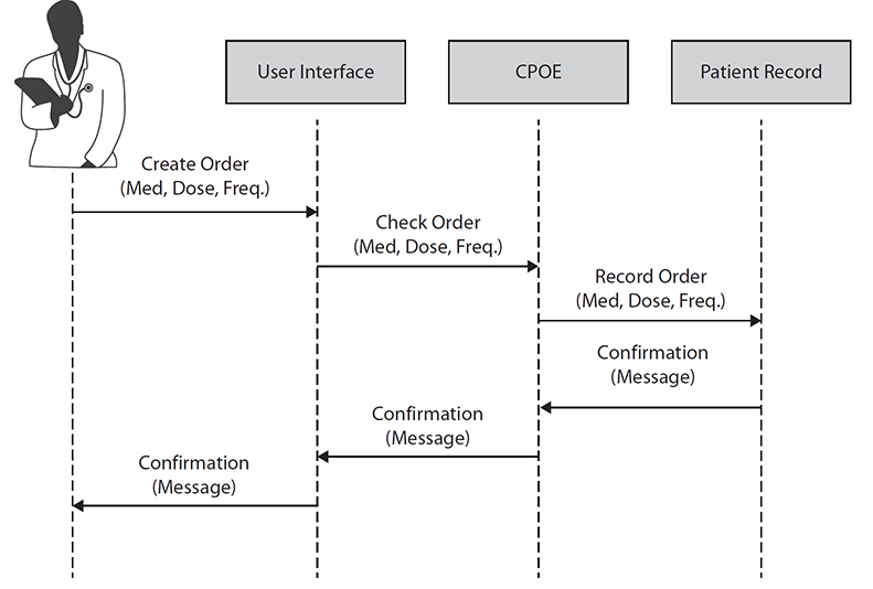
Figure 9-10 Sequence diagram for entering medications into a CPOE
You should consider many principles of good design when developing HISs. For example, the concept of designing components of systems so that they are modular is one of the most important concepts. By good modularity we mean that the components or modules of a system have high cohesion, which means that each module focuses on one task and does that task well, as opposed to carrying out many functions. If a module is associated with more than one main task, it should be broken up or decomposed into submodules. Additionally, good modularity is associated with loose coupling, where the system modules do not interact closely with each other but are somewhat self-contained and do not inadvertently cause side effects with other modules.1
In addition to good modularity, a range of other good system design principles exist. For example, design patterns have emerged as sets of templates to speed up OO system development.8 One group of design patterns states that systems should be developed in layers that can be easily interchanged or modified. For example, a typical three-layer system architecture consists of the following layers:1 the user interface, or view layer; the business logic layer (containing the programming logic to run applications); and the data layer (the underlying database that the system reads and writes data to). The user interface, or view layer, is the part of the system that the user interacts with. If it is designed in a modular and self-contained way, with only a few well-defined connections and easily locatable interfaces to the layer immediately below it (the business logic layer), then as user interface technology improves, a new user interface can be added to the system easily by replacing that one layer. However, this will become difficult to do, or next to impossible to do easily, if the system’s user interface calls or interacts extensively with the business logic layer below it. Likewise, if there are only a few clear and easily identifiable interfaces between the business logic layer and the underlying database layer, a new, more modern type of underlying database can be installed that will not require extensive reprogramming of the layers above it.
The Implementation Phase
Upon completion of the Design phase, the development project moves into the Implementation phase, where the design is translated into a working system by building running program code. This is the phase where the software of the HIS is constructed (or programmed), integrated with the required hardware, tested, and made ready for use in healthcare settings. The approach taken for implementation will depend on the system analysis and design methodology chosen and the type of programming languages and programming tools available. For example, if the traditional structured approach was used with the system analysis and design, then diagrams such as the structure charts would be developed to show how modules work together. In transitioning from design to implementation, the modules contained in the structure chart, as shown in Figure 9-9, are described in detail in terms of the programming code needed to carry out the function of each module. For example, the corresponding pseudocode (i.e., English-like specification of programming steps) for the top-level boss module Create New Medication Order in Figure 9-9 would serve to “call” the three modules directly below it (Record Medication Information, Process Medication Order, and Produce Confirmation). To do this, the pseudocode corresponding to this top-level module might look like the following:
Do until no more orders
Call module Record_Medication_Information;
Call module Process_Medication_Order;
Call module Produce_Confirmation;
This program-like code will be translated into the actual programming language used to implement the HIS, such as the C programming language or Java. Likewise, all the modules specified during the Design phase and represented in diagrams such as structure charts will be elaborated during the Implementation phase with programming code, as shown in Figure 9-11. This will eventually lead to a set of fully functional modules or a fully functioning HIS.
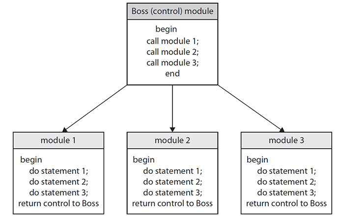
Figure 9-11 Example of a structure chart, with pseudocode programming statements
Top-down development refers to starting the development process (programming) with the module at the top of the structure chart. In contrast, bottom-up development refers to starting with the modules at the bottom of the structure chart, elaborating those modules with programming code first.1 With the object-oriented methods, we approach this a slightly different way typically, by scheduling (i.e., elaborating with code) use cases. The first use cases to be scheduled are those that are judged by the developers to be most critical, risky, or important in the development of the HIS, such as a use case that other components of the HIS may rely on or that must work in order for all the other functions of the system to work.8 We then proceed with developing use cases judged to be less critical, once the main or most critical ones have been shown to work, at least as partially working prototypes.
These resulting program codes that correspond to different modules (or use cases) in the system’s design can be tested individually through unit testing, where code corresponding to a module is tested on its own, or all program codes can be tested together with integration testing. Testing software systems and HISs in particular is an important area, and we refer you to complete books on this topic.9 Here, we will briefly define two main approaches to testing of HIS software: black-box testing and white-box testing.
Black-box testing, also known as testing with blinders on, refers to testing a system by giving the system specific inputs and then testing to determine whether the right outputs result.10 For example, you may black-box test a clinical decision support system that produces drug alerts in response to the entry of drugs that a patient might have an allergy to. You can do this by creating a list of drugs to be inputted into the system that should trigger the system to output drug alerts. The output of the system, in this case alerts, would then be compared to expected outputs to determine whether the system is working properly for all test cases (i.e., the system produces alerts when expected and does not produce alerts when not expected to). Black-box testing does not require that the testing team have knowledge of the underlying computer processes or software and is often used to test commercial vendor–based systems in hospitals when they are initially installed to check their correctness and safety.
In contrast, white-box testing, also known as glass-box testing, requires knowledge of underlying program code and internal aspects of a system. With this type of testing, specific parts of the software’s underlying logic are “stepped through” (examined by a team of programmers and analysts) to determine whether the computer logic is working as expected.10 It is important to note that as important as white- and black-box testing are, HISs are typically deployed in healthcare contexts that are much more varied and complex than other types of computer applications and also require extensive user acceptance testing, usability testing, and testing in the real setting of use.11 These methods focus on user interactions to determine whether the HIS is usable, safe, and enjoyable (or not) to use in real and complex healthcare settings.
The Support and Maintenance Phase
Once the HIS has been put into place in a healthcare setting, the ongoing process of support and maintenance of the system begins. The system may be in place for a long period of time; however, over time, there are always changes that need to be made to improve it, make it more efficient, or make it more likely to be adopted. Furthermore, HISs are inevitably replaced over time as their hardware or software becomes obsolete. Therefore, over time new systems analysis has to be conducted to determine requirements for system modification or termination. Thus, system development is seen as being cyclical, where the progress from planning to support/maintenance then eventually begins again when existing systems need to be updated or replaced. This is depicted in Figure 9-2 by the arrow going back from the Support (Maintenance) phase to the Planning (Needs Analysis) phase.
Trends and Issues in HIS Analysis and Design
Approaches to the development of complex systems such as HISs have evolved considerably over the past few decades. The traditional model for developing systems is often called the classic waterfall life cycle. This approach to the SDLC involves the stages described earlier (Planning, Analysis, Design, Implementation, and Support) following one another in such a way that one follows the other in strict sequential order (see Figure 9-12). Once Analysis is complete, the requirements are finalized, and the project moves to the Design phase. Once the Design phase is complete, the project moves to the Implementation phase, and once that phase is complete, the project moves to the Support phase. The approach is like a waterfall, since as the development process moves down to the next phase, it is difficult to go back to the previous phase. Therefore, the project “flows” downward. At each phase, the results, or the requirements specification produced from the Analysis phase, are typically “signed off” as complete by both the developer and the client before moving to the next phase. After the system is in place, the up arrows in the figure indicate that parts of the process may need to be modified or updated. This is typically costly and difficult to do once the system has been implemented. This type of model has been used successfully for many types of IT applications, particularly for traditional software applications such as standard business systems such as payroll applications.1 For more complex types of applications such as complex EHRs, clinical decision support systems, patient applications, or public health informatics systems, this approach has the drawback of expecting that most if not all user requirements can be gathered once and for all during the Analysis phase. Likewise, once the design of the system is set in the Design phase, it may be difficult and costly to try to go back to the Analysis phase as the project moves on and the Analysis phase has already been signed off as completed. In applications that are complex and that may require some piloting or experimentation, this approach may not be the best. Likewise, applications such as advanced EHRs, clinical decision support systems, and many emerging types of health applications typically require continual user evaluation and input, particularly if they are highly interactive systems.7

Figure 9-12 The classical “waterfall” life cycle
An alternative to the classic waterfall approach is known as rapid prototyping. This approach, which has become increasingly popular as systems become more complex, involves cycles of design, construction, and refinement of prototypes (which are incomplete but partially working versions of the system) and evaluation with end users (see Figure 9-13). In this approach, it is not assumed that initial requirements will be completely obtained at the very beginning of the development process but rather that enough requirements need to be gathered in order to start developing a working and testable prototype that is then evaluated to determine whether more requirements and design are needed (i.e., the arrow going from the Evaluation box back to the Requirements Gathering box in Figure 9-13). This cycling may continue until no more iterations are needed, such as when an evaluation indicates that final engineering of the system can be carried out or until time or money runs out. Variations of this may involve setting a fixed length of time for each iteration (an approach known as time boxing), in which testable and continual progress can be demonstrated in developing software components.12

Figure 9-13 Rapid prototyping
Agile software development is an approach to developing systems that involves prototyping and that has emerged as a way to develop systems rapidly. Some key principles of Agile development are the following:12
• Make customer/user satisfaction the main goal through early and continuous delivery of valuable and useful software.
• Changing requirements are welcome, even in later stages of system development.
• Prototypes and working software should be delivered at frequent intervals.
• End users and developers should work together daily throughout the project.
• Face-to-face communication is effective for conveying information during design.
• Working software is the main measure of progress.
• There should be continuous attention to technical excellence.
• Simplicity is a goal.
• Self-organizing teams should be encouraged.
• The team should reflect on progress at regular intervals.
These principles of system design and implementation should be considered in HIS development as they have been shown to be important in delivery of systems that are more likely to be adopted by end users.13
We refer you to other books to obtain details about the many possible variations of the previous models for carrying out the SDLC.4 Because HIS development is complex, a thorough understanding of the options in selecting approaches to developing such systems is becoming ever more critical. Some of these variations include combining the advantages of rapid prototyping with the classic waterfall approach. For example, for applications where there is uncertainty about whether technical requirements can be met, as in some complex HIS initiatives, a first phase of rapid prototyping might be appropriate in order to assess whether the system is technically feasible and to gain information that can be used in planning out a more fixed development process. In this case, after obtaining information about technical and user requirements from building prototypes, the classic waterfall approach can be initiated in order to develop and complete the HIS. The advantages here include a better ability to estimate the time and difficulty of the different stages of the waterfall approach as well as the reduction of the risk of system development failure. Prototyping may determine that a planned HIS may not be as achievable as initially conceived before going in to an expensive and difficult-to-modify waterfall development phase. Many of these ideas are now incorporated in OO systems analysis and design, with approaches such as the aforementioned Agile programming, which promotes considerable flexibility in the ordering and sequencing involved in developing a system; the Unified Process, which employs time boxing as described earlier; and Extreme Programming, which involves carrying out fast and iterative cycles of system development. For more information about these approaches, we recommend you look at McConnell and other sources.4
As a final consideration, it should be noted that in HIT, many organizations, particularly hospitals or health authorities, may be involved in a combination of “building” system components and “buying” and subsequently integrating system components. This distinction is often referred to as the buy versus build distinction, where the management of healthcare organizations must decide which parts of an HIS will be developed and programmed from scratch and which will be purchased either as completed software systems or as software components to be integrated with existing healthcare IT. This has a number of implications, including deciding whether a healthcare organization has the capability to develop a system or should purchase a completed solution from an HIS vendor. A related decision is with regard to what extent a healthcare organization’s HISs should be purchased from the same vendor or from a variety of different vendors (also known as the best-of-breed approach). Regardless of whether you are involved in development of HIT and HIS from scratch, such as developing HIT applications from planning through to design and implementation, or you are working in an organization considering buying a completed off-the-shelf HIT or HIS, an understanding of the principles of health information systems analysis and design is essential for successfully deploying information technology that has a good chance of supporting and improving healthcare.
Chapter Review
The development of HISs is complex, and systems that are used in healthcare settings must be carefully designed to meet the intended needs safely and efficiently. The core of development of an effective HIS is good systems analysis and design. This involves understanding the information needs of healthcare professionals, including the technical, functional, and nonfunctional requirements for a new HIS. In addition, the concept of the systems development life cycle is central to systems analysis and design, because it provides a framework from which to consider the development of systems, from the initial Planning phase all the way through to the Analysis and Design phases and then finally to the implementation and deployment of the system in a healthcare facility. In this chapter, we described a variety of diagramming and modeling tools that are routinely used to support HIS analysis and design. The traditional, structured approach includes data flow diagrams, entity relationship diagrams, and structure charts. The alternative approach, known as OO systems analysis and design, employs use case, class, and sequence diagrams. It is important for anyone engaged in systems analysis and design in HIT to be familiar with these approaches, tools, and methodologies. In addition, it is becoming increasingly important for those designing HISs to have an understanding of the trends in the analysis, design, and testing of HISs.
Questions
To test your comprehension of the chapter, answer the following questions and then check your answers against the list of correct answers at the end of the chapter.
1. Which is an example of an object-oriented diagram that depicts overall system requirements?
A. Sequence diagram
B. Use case diagram
C. Data flow diagram
D. Entity relationship diagram
2. What does the SDLC do?
A. Provides guidance in system development
B. Provides a checklist of activities
C. Provides a set of stages for system development
D. All of the above
3. What does the classic waterfall life cycle do?
A. Assumes that most requirements can be obtained early on in the SDLC
B. Allows for flexibility in carrying out systems analysis and design activities
C. Allows for easily redoing phases
D. Is well suited for the development of a complex interactive HIT application
4. Black-box testing refers to what?
A. Testing the internal logic of a health information system
B. Testing system components in isolation
C. Testing system components in an integrated manner
D. Testing systems without considering underlying program logic
5. What is rapid prototyping?
A. It involves iterative cycles of development and testing.
B. It is often associated with object-oriented development approaches.
C. It is useful in designing complex or highly interactive systems.
D. All of the above.
E. None of the above.
6. Which of the following is not true about Agile design?
A. Ensuring end user satisfaction is the highest goal.
B. Requirements should not be changed after the system design phase is complete.
C. Time-boxing can be used to drive iterative cycles of development.
D. The best designs often emerge from self-organizing teams, so this should be encouraged.
Answers
1. B. An example of an object-oriented diagram that depicts overall system requirements is a use case diagram.
2. D. The systems development life cycle (SDLC) involves the following phases: Planning, Analysis, Design, Implementation, and Support. It involves activities and phenomena such as guidance in system development, a checklist of activities, and a set of stages for system development.
3. A. The classic waterfall life cycle assumes that most requirements can be obtained early on in the SDLC and that those requirements remain fundamentally static and stable during the entire SDLC.
4. D. Black-box testing refers to testing systems without considering underlying program logic.
5. D. Rapid prototyping involves iterative cycles of development and testing, is often associated with object-oriented development approaches, and is useful in designing complex or highly interactive systems.
6. B. Using the Agile approach, changes to requirements are welcome throughout the entire process of system development, even during later stages and after initial system design has been completed.
References
1. Satzinger, J. W., Jackson, R. B., & Burd, S. D. (2002). Systems analysis and design in a changing world. Course Technology—Thomson Learning.
2. Shortliffe, E., & Cimino, J. (2006). Biomedical informatics: Computer applications in health care and biomedicine. Springer.
3. Cysneiros, L., & Leite, J. (2004). Nonfunctional requirements: From elicitation to conceptual models. IEEE Transactions on Software Engineering, 30, 328–350.
4. McConnell, S. (1996). Rapid development: Taming wild software schedules. Microsoft Press.
5. Martin, M. P. (1991). Analysis and design of business information systems. MacMillan.
6. Satzinger, J. W., & Orvik, T. U. (2001). The object-oriented approach: Concepts, system development, and modeling with UML. Course Technology—Thomson Learning.
7. Kushniruk, A. W. (2002). Evaluation in the design of health information systems: Applications of approaches emerging from systems engineering. Computers in Biology and Medicine, 32, 141–149.
8. Larman, C. (2002). Applying UML and patterns: An introduction to object-oriented analysis and design and the unified process. Prentice Hall.
9. Patton, R. (2001). Software testing. Sams.
10. Kaner, C., Falk, J., & Nguyen, H. (1999). Testing computer software. John Wiley & Sons.
11. Kushniruk, A., Borycki, E., Kuo, M. H., & Kuwata, S. (2010). Integrating technology-centric and user-centric testing methods: Ensuring healthcare system usability and safety. Studies in Health Technology and Informatics, 157, 181–186.
12. Ambler, S. W. (2002). Agile modeling: Effective practices for eXtreme programming and the unified process. John Wiley & Sons.
13. Ratcliffe, L., & McNeil, M. (2012). Agile experience design: A digital designer’s guide to Agile, lean and continuous. New Riders.