4
Voltage and Current: Direct and Alternating Current and Voltage
4.1 Introduction
In the last chapter we have described the characteristics behind difference in electric potential, electric fields, and current.
In this chapter, we will describe direct current (DC) and alternating current (AC) and voltage.
4.2 Terminology
The term “direct current” is used indiscriminately to refer to direct voltage and to direct current. In this book we will differentiate the terms to prevent confusion. The same thing is valid for “alternating current,” which in the real world is used to refer to both alternating voltage and alternating current.
Other terms also used are VDC to refer to “DC voltage” or direct (continuous) voltage and VAC to refer to “AC voltage” or alternating voltage.
4.3 Batteries
Around 1800, Alessandro Volta reported the results of an experiment where he was able to create electricity by piling discs of zinc and copper separated by felt spacers soaked in salt water. With this invention, Volta proved that electricity could be generated chemically and debunked the prevalent theory that electricity was generated solely by living beings.
A new invention was born: the battery.
4.3.1 Battery Life
Batteries are electrochemical devices created by embedding two different metallic plates into a third one. This third one, the electrolyte, is responsible, broadly speaking, for creating a chemical reaction in such a way that one of the elements ends with excess of electrons (negative charges) and the other one with an excess of positive charges – in other words, to create an imbalance of charges between the plates.
To summarize how chemical energy is converted into electrical energy, let us take an example of a typical car battery: one plate of pure lead and another one made of lead dioxide both immersed in a solution of sulfuric acid diluted with water. Chemical reaction causes the lead to become negatively charged and the lead dioxide to become positively charged.
The element with excess of electrons will be the negative pole (cathode) and the other element will be the positive pole (anode).
This difference in the number of electrons between the poles is called “difference in electric potential” or popularly, “voltage.”
Any element, like a light bulb, for example, connected between the poles, will provide a path for the excess of electrons of the lead element to migrate to the lead dioxide, which lacks electrons. As the reaction happens, most of the sulfuric acid in the electrolyte is consumed and used to convert both plates into lead sulfate, and the electrolyte turns into, mostly, regular water.
At some point, all three elements are electrically balanced, current stops flowing, and the battery dies.
The process of charging the battery will apply energy to the plates and electrolyte to reverse the reaction, making the plates to be lead dioxide and lead and the electrolyte sulfuric acid and water, again.
4.3.2 Batteries in Series
Consider two identical batteries connected in series, like shown in Figure 4.1. The positive pole of one battery is connected to the negative of the other and two wires are connected to points A and B.
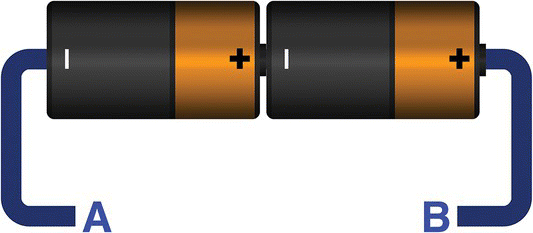
Figure 4.1 Batteries in series.
If each battery has a voltage of 1.5 V, two batteries connected in series will provide a combined voltage of 3 V. This will be the value measured across A and B.
Batteries can only provide a limited amount of current. If each battery on the given example can provide 0.2 A of current, connecting any number of batteries in series will not change that.
Conclusions:
- Two power supplies in series will have their voltages added.
- Two power supplies in series will not have their currents added.
4.3.3 Batteries in Parallel
Figure 4.2 shows two identical batteries connected in parallel. The positive poles and negative poles are connected together.

Figure 4.2 Batteries in parallel.
Supposing each battery can provide 1.5 V and 0.2 A,1 the voltage across AB will be 1.5 V, and together the batteries will be able to provide 0.4 A of current, which is the sum of their individual currents.
Conclusions:
- Two power supplies in parallel have their currents added.
- Two power supplies in parallel will not have their voltages added.
4.4 Danger Will Robison, Danger!
When connecting batteries in series or parallel, a few rules must be followed.
4.4.1 Never Invert Polarities
Inverting a battery in a block of batteries in series, like shown in Figure 4.3, or in parallel may represent a danger situation.

Figure 4.3 Incorrect connection.
The other batteries will force current circulation across the inverted one, generating excessive heat that may lead to fire hazard and explosions.
4.4.2 Never Use Different Batteries
A battery is only capable of providing a limited amount of current and voltage.
If you connect batteries with different current capabilities in series, for example, 2, 4, and 6 A, the largest battery will force 6 A of current through batteries that cannot handle that amount of current. Excessive heat may be generated, again creating a danger situation.
The same is true for batteries with different voltages in parallel.
4.4.3 Short‐Circuiting Batteries
Never short‐circuit a battery like shown in Figure 4.4. Current will flow between them, at maximum level, making both batteries explode and catch fire.
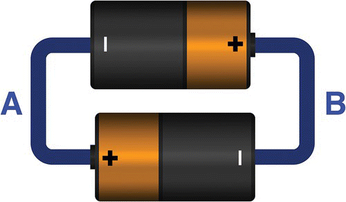
Figure 4.4 Batteries in short circuit.
4.5 Direct Current
Direct current or DC is a term used to refer to the kind of voltage or difference in potential that keeps its value constant over time and does not vary in amplitude or frequency.
Figure 4.5 shows the symbol used to refer to a source of DC. In that case, the symbol is used to refer to batteries.
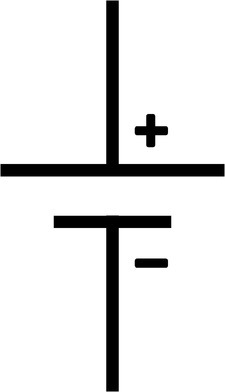
Figure 4.5 Battery symbol.
Batteries are sources of DC, meaning that once created they will provide a constant voltage and current during its lifetime.
4.5.1 DC Characteristics
- Current and voltage are constant over time.
- They are generated by chemistry and are very difficult to deploy in large scale.
- They never change polarity over time.
- Current only flows in one direction during all time.
- A DC voltage is not able to cross large distances. They lose power, considerably, if transmitted over long distances.
4.6 Relative Voltages
Consider two different electric potentials, like two batteries in series. How relative is the potential of one battery in respect with the other?
If each battery provides 1.5 V and two batteries in series provide 3 V, what are the references to which we are measuring these numbers?
What potential is positive and what potential is negative? Is a potential really positive or negative? In relation to what?
4.6.1 Mountains
To understand why, consider two mountains like shown in Figure 4.6 and a path that one can climb from A to C, including a point B in the middle.
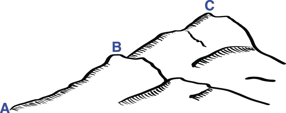
Figure 4.6 Two mountains.
A person standing on point A can climb to C in two phases: from A to B, resting at B a little bit, and then from B to C.
In terms of physics, the climber is going against gravity and, by doing so, accumulates gravitational potential energy.
Gravitation potential energy is calculated by the following formula.
If point A is at sea level, B is at 100 m, C is at 200 m, and a person weights 70 kg, we can use the given formula and calculate that the person will gain a potential energy of 68.6 kJ by climbing from A to B and the same amount, again, by climbing from B to C.
If we choose point A as zero reference, we conclude that the person will have a potential energy of zero at point A, 68.6 kJ at B, and 137.2 kJ at C.
What happens if instead of point A we select point B as zero reference?
If we do, we conclude that point C is 68.6 kJ over B and A is 68.6 kJ under B. In other words, in relation to B, the energy at C is 68.6 kJ and the energy at A is −68.6 kJ.
The negative sign is used to indicate that the potential level of A is below the reference point.
Now consider two batteries in series, like shown before, but, this time, we take them apart to include a third point B, like shown in Figure 4.7.
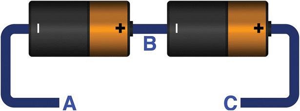
Figure 4.7 Batteries in series with an intermediary point.
Figure 4.7 shows three points: A, B, and C. No need to remember the mountain analogy.
If each battery can provide a voltage of 1.5 V and we use point A as zero reference, we see that point B will be 1.5 V and point C will be 3 V above A.
On the other hand, if we use point B as a zero reference, C will be at 1.5 V above B and A will be −1.5 V below B. Again, the negative sign is used to show that A is below B.
This example shows the concept of negative electric potentials that are nothing more than a way to tell if a voltage is above or below a zero reference. This zero‐reference point is called ground point, or simply ground, or in some cases, earth point.
4.7 Ground
In an electric circuit, the zero reference is called ground. The most used abbreviation in schematics is GND and its symbols are shown in Figure 4.8.

Figure 4.8 Ground symbols.
4.8 Alternating Current
AC is a term used to refer to an alternating voltage or to an alternating current source.
An alternating voltage changes its amplitude values constantly over time in a repeating pattern.
Like the alternating voltage, an alternating current also changes its amplitude values over time as well but additionally inverts polarity in a repeating pattern.
Figure 4.9 shows the symbol used for AC voltage sources in schematics.

Figure 4.9 Alternating current voltage source symbol.
4.8.1 AC Characteristics
- Can be easily created in large or small scale with electric generators.
- The levels of voltage and current vary cyclically with time.
- Voltage polarity may change with time.
- Current direction changes with time.
- Can travel large distances over wires with minimum losses.
4.8.2 AC Cycles
Figure 4.10 shows a graph representing an alternating voltage.
In Figure 4.11, we can see that alternating waves have a positive cycle and a negative cycle and vary over time in intensity.
The wave starts at 0 V, increases until it reaches V+, and then decreases to a negative level V−, repeating the whole pattern after that, ad infinitum.
Because the alternating voltage follows a cyclic pattern going up and down constantly, over time, it oscillates at a specific constant frequency. This frequency is measured in Hertz,3 meaning cycles per second,4 and is represented in the SI by the letters Hz.
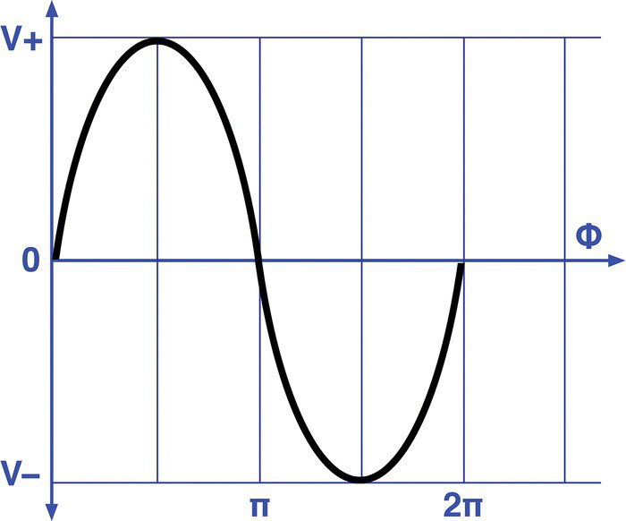
Figure 4.10 Alternating voltage.
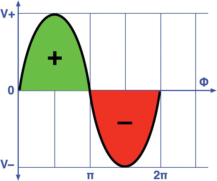
Figure 4.11 Alternating current cycles.
4.8.3 Period and Frequency
Figure 4.12 shows that the alternating wave starts at 0 and goes up and down and after a period equal to T starts repeating it.
In the given example, T is equal to 4 s and is known as the wave’s period of oscillation.
The frequency and the period of a wave are related by the following formula.
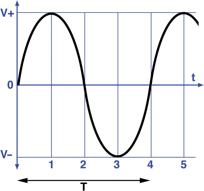
Figure 4.12 Period of a sinusoidal wave.
4.8.4 Peak‐to‐Peak Voltage
Consider the wave shown in Figure 4.13, where voltages vary from 20 to −20 V. These values are measured against the 0 and are called peaks.
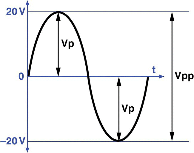
Figure 4.13 Alternating current peaks.
Remembering the mountain analogy, we can now use the negative peak as zero reference. If so, we can say that the positive peak is 40 V above that. In other words, 40 V is the difference between both peaks, also known as peak‐to‐peak voltage.
4.8.5 DC Offset
We have described DC and AC as two separate entities, but we never said that they cannot exist together.
Observe the alternating voltage shown in Figure 4.14. The wave reference rests, vertically, at 0 V. The wave varies from 20 to −20 V.

Figure 4.14 40 Vpp Alternating voltage.
Now suppose we add 10 V continuous to that wave. The result is seen in Figure 4.15.
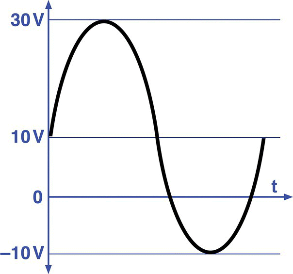
Figure 4.15 Alternating current plus 10 V DC.
By observing Figure 4.15, it is clear that the wave shifted up by 10 V. Now, its positive peak is at 30 V and its negative peak is at −10 V. The wave now rests, vertically, at 10 V and not at 0 V as before. We say, in that case, that an offset of 10 V was applied to the alternating voltage.
If the offset is negative, −10 V, for example, the wave of Figure 4.14 will shift down and be like the one shown in Figure 4.16. The wave now rests at −10 V and variates up and down to 10 V and −30 V, respectively. In other words, we pushed the wave down by 10 V.
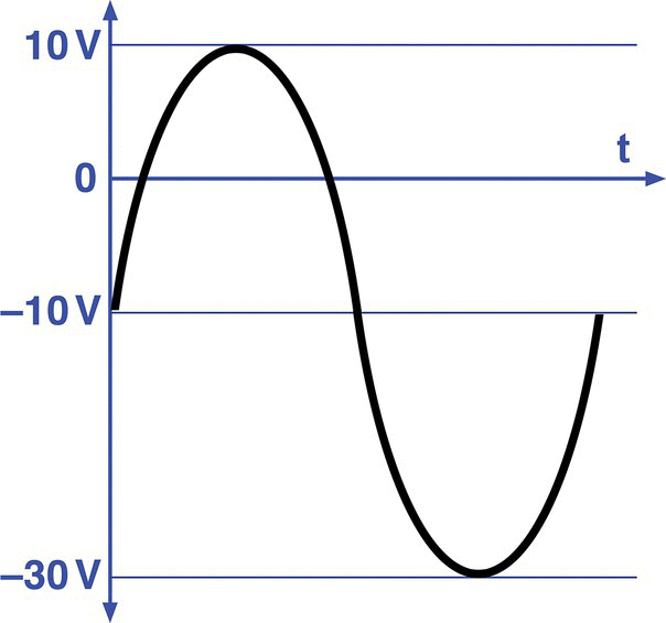
Figure 4.16 Alternating current minus 10 V DC.
Exercises
- Consider the circuit shown in Figure 4.17, composed of several power supplies. Find the voltage between points A and B.
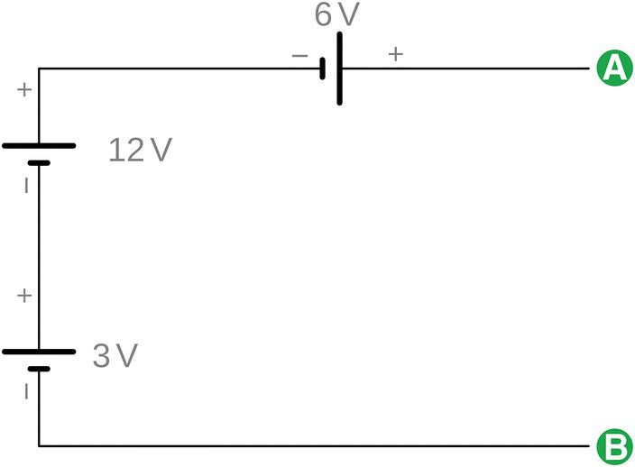
Figure 4.17 Batteries in series (Exercise 1). - Consider the same circuit shown on Figure 4.17. The three batteries of 3 V, 12 V, and 6 V are capable of providing 2 A, 4 A, and 3 A, respectively. Find the maximum current this circuit can provide.
- Circuit shown on Figure 4.18 is composed of three power supplies. Find the voltage between points A and B.

Figure 4.18 Batteries in series (Exercise 3). - Consider a 12 V alternating voltage power supply in series with an 8 V direct voltage power supply. What are the resulting peak voltages of this combination?
- Find the period of oscillation of a 60 Hz AC power supply.
Solutions
- If we follow the circuit from point B to A, we cross the 3 V power supply from the negative to the positive pole. It means that we are going from a point of low electric potential to a point of high electric potential and consequently we went up 3 V.
If we continue to follow the circuit, we cross the 12 V battery, again, from the negative to the positive pole, increasing the potential an additional 12 V.
The same will happen to the third battery, raising the potential an additional 6 V.
So, the voltage across AB is the sum of these three potential increases.
- Batteries with different current capabilities should never be connected in series and may lead to fire hazard or explosion.
- If we follow the circuit from B to A, we will cross the first voltage source (3 V) from its negative to its positive pole, a 3 V increase in potential.
As we continue to follow the circuit, we cross the second battery (12 V), from the positive to the negative pole, meaning a potential decrease of 12 V.
As we cross the third battery (6 V), we see an increase of 6 V.
So, the voltage across AB is equal to
The negative sign means that B’s potential is lower than A’s.
- If a source of alternating voltage has an amplitude of 12 V, it means it can reach a positive peak of 12 V and a negative peak of −12 V.
An 8 V direct voltage source added to this alternating source will shift the wave 8 V up. So, the wave will now reach a positive peak of 20 V(12 + 8) and a negative peak of −4 V(−12 + 8).
- The period of a wave is given by


Notes
- 1 This can be written as 1.5 V @ 0.2 A.
- 2 In honor of James Prescott Joule (1818–1889), English physicist. Joule is equivalent to kg.m2/s2 and represented by the uppercase letter J in SI.
- 3 In honor of Heinrich Rudolf Hertz, the first to prove, conclusively, the existence of electromagnetic waves.
- 4 A cycle is the period of time a wave needs to complete itself. Old schematics and books used the term cycles per second (cps) as a way to refer to wave frequency. It is not rare to find old texts referring to frequency as kcps (kilo cycles per second), instead of Hz.
