17
Impedance and Phase: Circuit Analysis
17.1 Introduction
In this chapter, we will examine impedance, admittance, and their relations with resistance and reactance, important themes of electrical engineering.
We will use complex numbers extensively. For anyone not familiarized with the concepts behind complex numbers, we advise to read Appendix D, before starting this chapter.
17.2 This Is Just a Phase
In previous chapters, we have examined capacitors and inductors and how these components respond when they are subjected to DC and AC.
Capacitance and inductance are not just properties of capacitors and inductors. In real life, all components, even resistors, have a little bit of both. In most cases these are spurious undesired properties of materials and construction methods.
Simple wires, for example, placed side by side, show capacitance and inductance properties that, in some cases, can prevent more sensitive circuits from working.
We have also examined how alternating current creates reactance in capacitors and inductors and how this reactance creates phase shifts between current and voltage and between input and output signals.
At the end, we have seen two kinds of resistances in a circuit: pure resistance that does not alter the phase of signals and reactance that alters the phase of signals.
Impedance is the sum of both, resistance, and reactance.
17.3 Impedance
Reactance and resistance cannot be added together directly because they are different entities.
To make the sum possible, we must express impedance as a complex number.
Complex impedance can represent resistance, reactance, and a phase angle at the same time.
17.3.1 Series Impedance
Like other components, impedances can be combined in series, and the total equivalent impedance (Z) will be the sum of all individual impedances, similar to the one used by resistors in series:
or in a generic form shown below.
17.3.2 Parallel Impedances
Impedances can also be combined in parallel, and the total equivalent impedance (Z) can be found by using the following formula, similar to the one used by resistors in parallel:
Like resistors, if we have just two impedances and parallel, we can use the following formula.
or in a generic form shown below.
17.4 Capacitive Impedance
Capacitors have no resistance, just reactance, which is given by
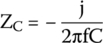
Thus, the impedance of a capacitor is shown below.
Considering that ω = 2πf, we can expand the formula.
Mathematically, the j in the denominator is not a good thing, because it will make future calculations harder.
To bring j to the nominator, we must use a mathematical technique – multiply nominator and denominator by j – an operation that will not alter the result.
Hence,
By applying this concept, we get
The negative sign shows that a capacitor will have a negative phase angle for the impedance.
17.5 Inductive Impedance
The reactance of an inductor is found by the formula
Thus, the inductor impedance will be
The positive sign on the impedance shows that inductors have a positive phase angle for the impedance.
17.6 Examples
17.6.1 Example 1
An alternating voltage source is applied to a resistor–capacitor circuit, as shown in Figure 17.1. How can we calculate the total impedance of this circuit?
17.6.1.1 Solution
The alternating voltage source’s peak is 10 V and its frequency is 60 Hz.
The capacitor impedance will be
Figure 17.1 Resistor, capacitor, and an AC source.
Thus,
Impedance is the real part (resistance) plus the imaginary part (reactance).
Hence, this circuit's impedance will be shown below.
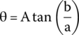
If we want to express impedance in the phasor form, we can use the formula in Appendix D:
The real part is positive. Therefore, the impedance's angle can be found by
The impedance in phasor notation will be shown below.
17.6.2 Example 2
Find the total impedance of the circuit shown in Figure 17.2.
Figure 17.2 Complex circuit.
17.6.2.1 Solution
The first branch of this circuit is equal to the one in the last example, to which we have already calculated its impedance as
For the second branch, we have the inductor impedance is given by
Thus,
Hence, the impedance of the second branch, as before, is the sum of the real part (resistance) and the imaginary part (reactance), or
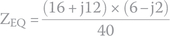
Both branches are in parallel. The total impedance of these branches can be found by the following formula:
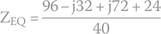
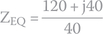
To perform this division, we must multiply nominator and denominator by the denominator's conjugate (see Appendix D):
or in the phasor notation
17.7 The Importance of Impedances in Real Life
Impedance is fundamental for electrical engineering when we must connect different circuits together. Incompatible impedances will prevent circuits from working.
17.7.1 Example
Consider both circuits in Figure 17.3. The first circuit contains a voltage source and two resistors, R1 and R2. The second one contains a resistor that represents the load. This load can be anything, a light bulb, a motor, etc.
Figure 17.3 Two independent circuits.
We want to connect both circuits by attaching electrically points A to C and B to D.
After the connection, we need the voltage between points A and B to be closer to the value it has before the connection.
17.7.1.1 Solution
The first thing we must do is to calculate the voltage between A and B in the first circuit alone, without any load.
We calculate the current flowing in the first circuit by using the Ohm's law:
Hence, voltage between A and B will be
We now connect the second circuit to the first one and see what happens to the voltage between A and B (Figure 17.4).

Figure 17.4 Two circuits connected.
After connecting both circuits, we see that RL is now in parallel with R2.
Therefore, we can substitute both by an equivalent resistor (Figure 17.5):
Figure 17.5 Final circuit.
Now we can calculate the current flowing in the circuit by using Ohm's law:
Voltage between A and B will be
We see that after connecting both circuits, the voltage between A and B dropped from 99.85 to 39.97 V. This is not what we want.
To understand what happened, remember that V = R × I.
Connecting both circuits puts R2, a 20 kΩ resistor, in parallel with RL, a 20 Ω resistor, making the resistance between A and B drop almost 1000 times, from 20 kΩ to 19.98 Ω.
This small resistor in combination with a 2 A produces a very small voltage.
17.7.1.2 What About a Bigger Load?
What happens if the load RL is 100 kΩ instead of 20 Ω?
Connecting both circuits puts R2, a 20 kΩ resistor, in parallel with RL, a 100 kΩ resistor, making the equivalent resistance
The current, according to Ohm's law, will be
Hence, the voltage between A and B will be
The voltage between A and B is practically the same as before, exactly what we want.
17.7.1.3 Conclusion
A circuit with a high output impedance connected to a low impedance load will make the output voltage drop and subject the output to a high current, probably making the circuit stop working.
On the other hand, a circuit with a low output impedance connected to a high impedance load will not create problems for the first circuit. The output voltage will not drop and the load will drain very little current.
Exercises
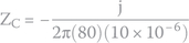
- Find the impedance of a circuit composed of a 22 Ω resistor in series with a 10 μF capacitor when an alternating voltage with a frequency of 80 Hz is applied.
- Find the impedance of a circuit composed of a 47 Ω resistor in series with a 100 mH inductor when an alternating voltage with a frequency of 60 Hz is applied.
- A circuit with an impedance equal to 4 − j2 Ω is connected in series with another one with an impedance of 2 + j4 Ω. What is the circuit's total impedance? Which circuit shows capacitive properties?
- What is the total impedance if we connect a circuit with an impedance equal to 4 − j2 Ω in parallel with another one with an impedance of 2 + j4 Ω?
- What is the phasor representation of an impedance equal to 3 + j5 Ω?
Solutions
- Capacitor's impedance is given by
Circuit's final impedance is the real part (resistance) plus the imaginary part (reactance).
- Inductor's impedance is given by


Circuit's final impedance is the real part (resistance) plus the imaginary part (reactance).
- The final impedance will be the two impedances in series:

The result shows inductive properties, because the imaginary part is positive.
The first circuit, with an impedance equal to 4 − j2, is the one that shows capacitive properties, because the imaginary part is negative.
- The equivalent impedance for two individual impedances in parallel is found by the following formula:
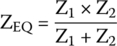
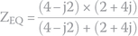

Hence,
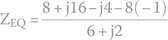

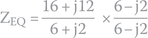
To perform this division, we must multiply nominator and denominator by the denominator's conjugate (see Appendix D):
- To calculate the module of impedance 3 + j5 Ω, we do
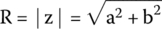

The angle can be found by


or in the phasor form