20
Nodal Analysis: Circuit Analysis
20.1 Introduction
In this chapter, we will examine a technique of circuit analysis called voltage node analysis or simply nodal analysis.
This technique can be used to find currents and voltages across a circuit by using a zero reference and a peculiar way to use Ohm's law.
20.2 Examples
20.2.1 Example 1
Consider the circuit shown in Figure 20.1, composed of several voltage sources and resistors. We want to find the voltage between points A and B and the several branch currents.

Figure 20.1 Nodal analysis.
20.2.1.1 Solution
First thing to do, according to the nodal analysis, is to choose a point to be the circuit's zero reference, that is, the ground point. We select point B and redraw the circuit to include a ground point, as shown in Figure 20.2.
Figure 20.2 Ground reference.
Now that we have a ground point, we can say that the voltages across points C and ground and across D and ground are equal to V1 and V2, or 80 and 20 V, respectively.
However, the voltage across A, which is between A and ground, is not immediately obvious. To find this voltage we must analyze the circuit.
20.2.1.2 Circuit Analysis
First Ohm's law tells us that I = V/R, meaning that current is equal to voltage divided by resistance. This is the principle used by nodal analysis.
20.2.1.3 Kirchhoff's Laws
In Figure 20.2, we have established, randomly, three branch currents, i1, i2, and i3.
According to Kirchhoff's current law (KCL), the sum of the currents that arrive at a node is equal to the sum of the currents that leave the same node.
Thus, we can write the following equation for node A:
20.2.1.3.1 Current i1
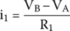
Resistor R1 is subjected to two voltages: the voltage across point A and the voltage across point C. Therefore, the voltage across R1 will be the subtraction of these two voltages, or
If current is equal to voltage divided by the resistance, or I = V/R, current across R1 will be
20.2.1.3.2 Current i2
Voltage at point A is the difference between voltages of A and B divided by the value of R2. However, the voltage at B is 0, because this point is the ground reference.
Therefore, voltage across R2 is
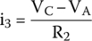
20.2.1.3.3 Current i3
We can calculate i3 by using the same principle we have used to find i1:
Again, the subtraction order follows the direction of i3.
20.2.1.3.4 Bringing It All Together
Solving this equation will give us the following.
We can now find the currents
The negative sign found for i3 shows that this current flows in the opposite direction compared with the arbitrarily chosen direction, from point A to D, entering V2 by the positive pole. Therefore, V2 is absorbing power from the circuit and V1 is the source driving the circuit.
20.2.2 Example 2
To prove that the directions chosen for the arbitrary currents are irrelevant, we will now examine an impossible circuit, shown in Figure 20.3.

Figure 20.3 Impossible circuit.
We want to find the voltage across R2 (points A and B) and the currents, i1, i2, and i3.
However, this circuit has an unusual problem: all currents leave node A, something impossible in real life.
20.2.2.1 Solution
To begin the nodal analysis, we choose point B and establish the zero reference. The circuit is redrawn to include the change, as shown in Figure 20.4.
Figure 20.4 Establishing a ground reference.
20.2.2.2 Applying Kirchhoff's Laws
According to KCL, the sum of the currents entering a node is equal to the sum of currents leaving the same node, or, in other words, the sum of all the currents entering or leaving a node is equal to 0.
This gives us the following equation:
20.2.2.2.1 Current i1
By applying nodal analysis, i1 is equal to the voltage across R1 divided by its resistance:
Notice that VC = V1, equivalent to the power supply V1.
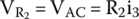
20.2.2.2.2 Current i2
By the nodal analysis, i2 is equal to the voltage across R2, that is, the voltage at point A subtracted from the voltage at point B, divided by its resistance. However, the voltage of B is 0, since this point is the ground reference, giving us the following equation:
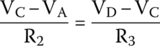
20.2.2.2.3 Current i3
By using the same principle, current i3 is equal to the voltage across R3, that is, voltage at point A subtracted from voltage at point D, divided by its resistance:
20.2.2.2.4 Bringing All Three Currents Together
Solving this equation gives us the following.
We can now find the currents
The negative sign for i1 shows that we got the direction wrong for this current and that it flows the other way around, from C to A.
We see that directions we choose for the currents are irrelevant. The math will always correct our mistakes.
20.2.3 Example 3
Consider the circuit shown in Figure 20.5.
We want to find voltages across A and B and the several currents shown in Figure 20.5.

Figure 20.5 Nodal analysis.
20.2.3.1 Node A
Two currents leave and one current arrives at node A.
KCL give us
Each one of the currents can be found by nodal analysis:
20.2.3.1.1 Bringing It All Together
20.2.3.2 Node B
Node B gives us
Current i3 is already known.
The other currents can be found by
20.2.3.2.1 Bringing It All Together
We end with two equations, (20.1) and (20.2), as shown below:
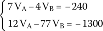
These equations can be solved by using matrices:
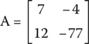
If we label each matrix with a letter
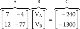
we can say that
If we want to find B, we should, in theory, divide C by A, but that is not possible with matrices. The correct way to find B in this case is to multiply C by the inverse of A:
Thus, the first thing we need to do is to calculate the determinant of A.
Therefore,
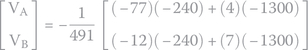
Hence, the inverse of matrix A will be
If we apply this result in (20.3), we get

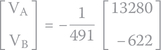
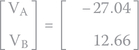
We see that VA is negative, meaning this point has an electric potential less than ground.
We can now calculate the several currents.
Once more, the negative sign of i2 shows that this current flows inversely, compared with the direction we have chosen for it.
Exercises
- Find the voltages at points A and C and the several currents assigned with arbitrary directions in the circuit shown in Figure 20.6.
Figure 20.6 Nodal analysis (exercise). - Find the voltage across R3 and the several currents assigned with arbitrary directions in the circuit shown in Figure 20.7.
Figure 20.7 Nodal analysis (exercise). - Find the voltage at point A and the several currents assigned with arbitrary directions in the circuit shown in Figure 20.8.

Figure 20.8 Nodal analysis (exercise).
Solutions
We choose point D as the ground reference and redraw the circuit to include the change, as shown in Figure 20.9.
Figure 20.9 Nodal analysis (exercise).
Observing Figure 20.9, we see that voltages B and A, taken in relation to the ground, are equal to V1 and V2 or 40 V and −15 V, respectively. We also see that voltage at point D is 0 V.
By applying nodal analysis, we get i1 and i3:

Current i3 will be equal to

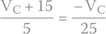
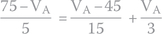
but will be also be equal to

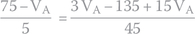
So, we can equal both equations
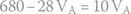
By substituting the values we have, we get


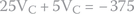

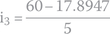
Therefore, we can calculate i3

Current i2 is found by applying KCL at node A


Current flowing from C to A will cause a voltage drop across R2 equal to

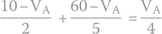
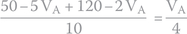
- By applying KCL to node A, we get

By applying node analysis for node A, we obtain
Putting it all together to get the voltage at point A:


We can now find the currents


- By applying nodal analysis for node A, we get
By applying KCL to node A,

Thus,


We can now find the currents


Voltage across point C and ground is equal to V2, that is, 45 V. The block V3/R4 is also connected between C and ground, parallel to V2. For that reason, V3/R4 has the same 45 V across.
If V3 is equal to −10 V,1 the voltage across the resistor R4 will have to be 55 V to make voltage across C and ground equal to 45 V (55 − 10 = 45 V).
Thus, current across R4 must produce a voltage drop of 55 V:


By applying KCL at node C, we get current i5:


Note
- 1 V3 is a negative source because its negative pole is connected to C and its positive pole is connected to ground through R4.